Sign In
Upload
Manuals
Brands
Keithley Manuals
PCI Card
KPCI-3116
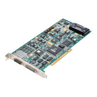
Keithley KPCI-3116 Multifunction Board Manuals
Manuals and User Guides for Keithley KPCI-3116 Multifunction Board. We have
1
Keithley KPCI-3116 Multifunction Board manual available for free PDF download: User Manual
Keithley KPCI-3116 User Manual (158 pages)
PCI Bus data acquisition board
Brand:
Keithley
| Category:
PCI Card
| Size: 5 MB
Table of Contents
Table of Contents
9
Preface
17
Intended Audience
17
What You Should Learn from this Manual
17
Viewing the KPCI-3110 and KPCI-3116 Documentation Online
18
Conventions Used in this Manual
18
Related Information
19
Where to Get Help
19
1 Overview
20
Introduction
21
Features
21
Driverlinx Software
22
System Requirements
23
Software
23
Accessories
24
2 Functional Description
25
Analog Input Features
26
Block Diagram of the KPCI-3110 and KPCI-3116 Boards
26
Figure
26
Analog Input Channels
27
Analog Input Resolution
27
Input Ranges and Gains
29
An Example Using Dynamic Digital Outputs
29
Figure
29
A/D Sample Clock Sources
30
Analog Input Conversion Modes
31
Triggers
34
Continuous Post-Trigger Mode Without Triggered Scan
35
Continuous Post-Trigger Mode with Triggered Scan
36
Figure
36
Continuous Pre-Trigger Mode
37
Continuous Pre-Trigger Mode with Triggered Scan
37
Figure
37
Continuous About-Trigger Mode
38
Figure
38
Continuous About-Trigger Mode with Triggered Scan
38
Data Format and Transfer
39
Error Conditions
39
Analog Output Features
40
Analog Output Resolution
40
Analog Output Channels
40
Output Filters
41
Output Ranges and Gains
41
D/A Output Clock Sources
41
Analog Output Conversion Modes
43
Data Format and Transfer
44
Error Conditions
44
Digital I/O Features
45
Digital I/O Lines
45
Digital I/O Operation Modes
46
Counter/Timer Features
46
Units
46
C/T Clock Sources
47
Figure 2-9 Counter/Timer Channel
47
Gate Types
48
Pulse Output Types and Duty Cycles
49
Table 2-3 Gate Input Signals
49
Counter/Timer Operation Modes
50
Figure 2-12 Example of Event Counting
51
(Shown for Clock Input 0)
52
Figure
52
Functional Description
53
Pulse Output Signals
56
Synchronizing A/D and D/A Subsystems
60
Synchronizing the Triggers
60
Synchronizing the Clocks
60
3 Installation and Configuration
61
Unpacking
62
Installing the Software
62
Software Options
62
Installing Driverlinx
64
Installing Application Software and Drivers
64
Installing the Board
65
Setting up the Computer
65
Selecting an Expansion Slot
65
Configuring the Board to Work with Driverlinx
67
Checking the Combined Board and Driverlinx Installations
67
Size
69
Jumper W1 - Common Ground Sense
69
Resistors R1 to R16 - Bias Return
70
Resistors R17 to R32 - Current Shunt
70
Screw Terminals
70
Table
71
Screw Terminal Assignments for Connector J1On the STP-3110 Screw Terminal Panel
71
Screw Terminal Assignments for Connector J2 on the STP-3110 Screw Terminal Panel
72
Wiring Signals
73
Connecting Analog Input Signals
73
Connecting Analog Output Signals
78
Connecting Digital I/O Signals
78
Connecting Counter/Timer Signals
79
4 Testing the Board
86
Driverlinx Analog I/O Panel
87
5 Calibration
89
Introduction
90
Objectives
90
Calibration Summary
90
Equipment
90
Calibration Procedure
91
Preparing for the Calibrations
91
Calibrating the Analog Inputs
91
Calibrating the Analog Outputs
91
6 Troubleshooting
92
General Checklist
93
Using the Driverlinx Event Viewer
93
Device Initialization Error Messages
93
Problem Isolation
94
Troubleshooting Table
95
Table
95
Troubleshooting Problems
95
Testing the Board and Host Computer
96
Testing the Accessory Slot and I/O Connections
96
Technical Support
97
Returning Equipment to Keithley
98
Specifications
99
Table
100
A/D Subsystem Specifications
100
Table
101
D/A Subsystem Specifications
103
Table
103
DIN/DOUT Subsystem Specifications
104
Table
104
C/T Subsystem Specifications
105
Table
105
Power, Physical, and Environmental Specifications
106
Connector Specifications
106
Supported Capabilities
107
Table
107
KPCI-3110 and KPCI-3116 Supported Options
107
Connector Pin Assignments
111
Table
112
Connector J1 Pin Assignments on the KPCI-3110 and KPCI-3116 Boards
112
Connector J2 Pin Assignments on the KPCI-3110 and KPCI-3116 Boards
113
Pin Assignments for Connector J1 on the STP-3110
114
Screw Terminal Assignments for Connector J2 on the STP-3110 Screw Terminal Panel
115
Systematic Problem Isolation
117
Problem Isolation Schemes
117
Problem Isolation Scheme A: Basic System
118
Problem Isolation Scheme B: Installation
120
Problem Isolation Scheme C: Application Software
126
Problem Isolation Scheme D: Expansion Slot Connectors
128
Problem Isolation Scheme E: User Wiring
128
Problem Isolation Scheme F: the Board
129
Problem Isolation Scheme G: Verification of Problem Solution
129
Specified Hardware I/O Tests
130
Analog Input Hardware Test
130
Table
131
Wiring for Analog Input Hardware Test Using an STP-3110 Screw Terminal Accessory Connected to the Analog I/O Connections
131
Analog Output Hardware Test
133
Terminals on STP-3110 Screw Terminal Accessory to Which DVM/DMM will be Connected During Analog Output Hardware Test
133
Table
133
Test Connections and Correct Readings for Zero-Voltage Analog Output, Using an STP-3110 Screw Terminal Accessory Connected to J1
135
Table
135
Test Connections and Correct Readings for MID-Range Analog Output, Using an STP-3110 Screw Terminal Accessory Connected to the J1 Connector
135
General-Purpose Digital I/O Hardware Test
136
100 C Systematic Problem Isolation
131
Specified Software I/O Tests
136
Analog Input Software Test
137
Wiring for Analog Input Hardware Test Using an STP-3110 Screw Terminal Accessory Connected to the Analog I/O Connections
137
Table
137
Analog Output Software Test
138
Terminals on STP-3110 Screw Terminal Accessory to Which DVM/DMM will be Connected During Analog Output Hardware Test
139
Table
139
Test Connections and Correct Readings for Zero-Voltage Analog Output, Using an STP-3110 Screw Terminal Accessory Connected to J1
140
Table
140
Test Connections and Correct Readings for MID-Range Analog Output, Using an STP-3110 Screw Terminal Accessory Connected to the KPCI-3110 or KPCI-3116 Board
140
General-Purpose Digital I/O Software Test
141
Using Your Own Screw Terminal Panel
144
Analog Inputs
144
Single-Ended Inputs
144
Pseudo-Differential Inputs
144
Differential Inputs
145
Analog Outputs
145
Digital Inputs and Counter/Timer Inputs
145
Digital Outputs
146
Advertisement
Advertisement
Related Products
Keithley KPCI-3101 Series
Keithley KPCI-3102 Series
Keithley KPCI-3103 Series
Keithley KPCI-3104 Series
Keithley KPCI-3160
Keithley KPCI-3110
Keithley KPCI-488 LPA
Keithley KPCI-PIO24
Keithley KPCI-PIO32IOA
Keithley KPCI-PDISO8A
Keithley Categories
Measuring Instruments
Multimeter
Test Equipment
Power Supply
Switch
More Keithley Manuals
Login
Sign In
OR
Sign in with Facebook
Sign in with Google
Upload manual
Upload from disk
Upload from URL