Sign In
Upload
Manuals
Brands
KEB Manuals
DC Drives
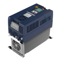
COMBIVERT 17G6 Series
KEB COMBIVERT 17G6 Series Manuals
Manuals and User Guides for KEB COMBIVERT 17G6 Series. We have
1
KEB COMBIVERT 17G6 Series manual available for free PDF download: Instructions For Use Manual
KEB COMBIVERT 17G6 Series Instructions For Use Manual (54 pages)
INSTALLATION G6 HOUSING E
Brand:
KEB
| Category:
DC Drives
| Size: 3 MB
Table of Contents
Preface
3
Signal Words and Symbols
3
More Symbols
3
Laws and Guidelines
4
Warranty and Liability
4
Support
4
Copyright
4
Table of Contents
5
List of Figures
8
List of Tables
9
Glossary
10
Standards for Drive Converters / Control Cabinets
12
Product Standards that Apply Directly to the Drive Converter
12
Basic Standards to Which Drive Converter Standards Refer Directly
12
Standards that Are Used in the Environment of the Drive Converter
13
1 Basic Safety Instructions
14
Target Group
14
Transport, Storage and Proper Use
14
Installation
15
Electrical Connection
16
EMC-Compatible Installation
17
Voltage Test
17
Insulation Measurement
17
Start-Up and Operation
18
Maintenance
19
Repair
20
Disposal
20
2 Product Description
21
Specified Application
21
Residual Risks
21
Unintended Use
21
Product Features
22
Type Code
23
Table 1: Part Code
24
3 Technical Data
25
Operating Conditions
25
Climatic Ambient Conditions
25
Table 2: Climatic Ambient Conditions
25
Mechanical Ambient Conditions
26
Chemical / Mechanical Active Substances
26
Table 3: Mechanical Ambient Conditions
26
Table 4: Chemical / Mechanical Active Substances
26
Electrical Operating Conditions
27
Device Classification
27
Electromagnetic Compatibility
27
Table 5: Device Classification
27
Table 6: Electromagnetic Compatibility
27
Technical Data 400V Class
28
Overload and Derating
29
Figure 1: Maximum Load and Derating Depending on the Switching Frequency
29
Figure 2: Overload Characteristic
30
Mechanical Installation
31
Dimensions and Weights
31
Built-In Version
31
Figure 3: Dimensions and Weights for Housing E Built-In Version
31
Push-Through Version
32
Figure 4: Dimensions and Weights for Housing E Push-Through Version
32
Flat Rear Version
33
Figure 5: Dimensions and Weights for Housing E Flat Rear Version
33
Control Cabinet Installation
34
Figure 6: Mounting Distances
34
Figure 7: Control Cabinet Ventilation
34
Control Cabinet Cut-Out for Push-Through Version
35
Ventilation in the Control Cabinet
35
Power Dissipation
36
Figure 8: Control Cabinet Cut-Out
36
4 Installation and Connection
37
Overview of the Combivert G6
37
Figure 9: Overview of the COMBIVERT G6
37
Connection of the Power Unit
38
Connection of the Voltage Supply
38
Wiring Instructions
38
Figure 10: Input Circuit / Drive Converter Type
38
Table 7: Technical Data 400V Class
38
Line Terminal Strip X1A
39
AC Connection
39
AC Supply 400V / 3-Phase
39
Supply Cable
39
Figure 11: Line Terminal Strip X1A
39
Figure 12: Connection of the Mains Supply
39
DC Connection
40
Connection at DC Voltage Supply
40
Terminal Strip X1B DC Connection
40
Figure 13: Connection at DC Voltage Supply
40
Figure 14: Terminal Strip X1B DC Connection
40
Connection of the Motor
41
Selection of the Motor Cable
41
Cable-Fed Disturbances Depending on the Motor Line Length at AC Supply
41
Motor Line Length at Operation with DC Voltage
41
Motor Cable Length for Parallel Operation of Motors
41
Motor Cable Cross-Section
42
Interconnection of the Motor
42
Terminal Strip X1B Motor Connection
42
Wiring of the Motor
42
Figure 15: Terminal Strip X1B Motor Connection
42
Figure 16: Wiring of the Motor
42
Connection of a Braking Resistor
43
Terminal Strip X1B Connection Braking Resistor
43
Wiring of an Intrinsically Safe Braking Resistor
43
Figure 17: Terminal Strip X1B Motor Connection
43
Figure 18: Wiring of an Intrinsically Safe Braking Resistor
43
Connection of a Temperature Detection
44
Temperature Detection Terminals T1, T2
44
Terminal Strip X1C Temperature Detection
44
Figure 19: Temperature Detection Terminals T1, T2
44
Figure 20: Terminal Strip X1C Temperature Detection
44
Use of the Temperature Detection
45
Final Test Information
45
Calculation of the Motor Voltage
45
Figure 21: Wiring Examples of the Temperature Input
45
Table 8: Calculation of the Motor Voltage
45
5 Accessories
46
Mounting Kit Shield Connection Braket Built-In Version
46
Figure 22: G6 Housing E Built-In Version with Optional Mounting Kit
46
Table 9: Mounting Kit Shield Connection Braket Built-In Version for G6 Housing E
46
Sealing Kit Push-Through Version
47
Ferrit Rings
47
Table 10: Sealing Kit Push-Through Version for G6 Housing E
47
6 Certification
48
Ce-Marking
48
Functional Safety
48
UL Marking
48
7 Revision History
51
Advertisement
Advertisement
Related Products
KEB COMBIVERT 17F5
KEB COMBIVERT 17F6
KEB COMBIVERT 18G6 Series
KEB COMBIVERT 19G6 Series
KEB COMBIVERT 10G6 Series
KEB COMBIVERT 13G6 Series
KEB COMBIVERT 14G6 Series
KEB COMBIVERT 12G6 Series
KEB COMBIVERT 15F5
KEB COMBIVERT 18F6
KEB Categories
DC Drives
Controller
Inverter
Control Unit
Industrial Equipment
More KEB Manuals
Login
Sign In
OR
Sign in with Facebook
Sign in with Google
Upload manual
Upload from disk
Upload from URL