Sign In
Upload
Manuals
Brands
KEB Manuals
Water Filtration Systems
COMBILINE 0DZ1I05-1001
KEB COMBILINE 0DZ1I05-1001 Manuals
Manuals and User Guides for KEB COMBILINE 0DZ1I05-1001. We have
1
KEB COMBILINE 0DZ1I05-1001 manual available for free PDF download: Instructions For Use Manual
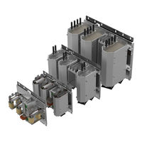
KEB COMBILINE 0DZ1I05-1001 Instructions For Use Manual (44 pages)
SINUS EMC FILTER
Brand:
KEB
| Category:
Water Filtration Systems
| Size: 13.26 MB
Table of Contents
Preface
3
Signal Words and Symbols
3
More Symbols
3
Laws and Guidelines
4
Warranty and Liability
4
Support
4
Copyright
4
Table of Contents
5
List of Figures
7
List of Tables
8
Standards for EMC Components
9
Product Standards
9
Basic Standards
9
General Standards
9
1 Basic Safety Instructions
10
Target Group
10
Transport, Storage and Proper Use
10
Installation
11
Electrical Connection
12
Start-Up and Operation
12
Repair
13
Disposal
13
2 Product Description
14
Intended Use
14
Improper Use
14
Product Features
14
3 Technical Data
15
Operating Conditions
15
IP Protection Classes
15
Climatic Conditions
15
Table 1: IP Protection Classes
15
Table 2: Climatic Conditions
15
Mechanical Ambient Conditions
16
Chemical/Mechanical Active Substances
16
Electrical Operating Conditions
16
Equipment Classification
16
Table 3: Mechanical Ambient Conditions
16
Table 4: Chemical/Mechanical Active Substances
16
Table 5: Equipment Classification
16
Electrical Data
17
Electrical Equivalent Circuit Diagram
17
Figure 1: Electrical Equivalent Circuit Diagram of the Sine EMC Filters
17
Table 6: Electrical Data
17
4 Installation and Connection
18
Schematic Diagram
18
Figure 2: Schematic Diagram
18
Figure 3: Motor Operation
19
Motor Operation
19
AIC Operation
20
Figure 4: Complete Circuitry with Additional Elements
20
Using The Sine-Wave Filter In Conjunction With Aic (Active Infeed Controller)
21
Connection Temperature Measurement and Fan
21
Figure 5: Connection Principle Filter Type 0D
21
Figure 6: Connection Principle Filter Types 0H
21
Table 7: Installation of a Complete AIC Filter
21
Overtemperature Shutdown
22
Rated Data of the Integrated Fans
22
Table 8: Voltage Supply of the Integrated Fans
22
Table 9: Rated Data NC Contact
22
Connection Power Terminals
23
Filter Type 0D
23
Figure 7: Filter Type 0D
23
Filter Type 0H and 0L
24
Figure 8: Filter Type 0H and 0L
24
Filter Type 0P and 0S
25
Figure 9: Filter Type 0P and 0S
25
Filter Type 0X and 0Y
26
Figure 10: Filter Type 0X and 0Y
26
Alternative Connection Option
27
Figure 11: Alternative Connection Option
27
Transport
28
Figure 12: Transport
28
Mechanical Construction
29
Dimensions Filter Type 0D
29
Figure 13: Dimensions Filter Type 0D
29
Table 10: Length of the Connection Cables Filter Type 0D
29
Dimensions Filter Type 0H And 0L
30
Figure 14: Dimensions Filter Type 0H and 0L
30
Table 11: Length of the Connection Cables Filter Type 0H and 0L
30
Dimensions Filter Type 0P And 0S
31
Figure 15: Dimensions Filter Type 0P and 0S
31
Table 12: Length of the Connection Cables Filter Type 0P and 0S
31
Dimensions Filter Type 0X And 0Y
32
Figure 16: Dimensions Filter Type 0X and 0Y
32
Table 13: Length of the Connection Cables Filter Type 0X and 0Y
32
Control Cabinet Installation
33
Installation Distances Of The Sine-Wave Emc Filters
33
Mounting Instructions for Control Cabinet Installation
33
Figure 17: Installation Distances of the Sine-Wave EMC Filters
33
Table 14: Mounting Instructions for Control Cabinet Installation
33
EMC Conform Installation in the Control Cabinet
34
Figure 18: EMC Conform Installation in the Control Cabinet
34
Fan Replacement
35
Figure 19: Fan Replacement
35
Table 15: Part Numbers of the Fans
35
5 Mode of Action
36
Sine EMC Filter in Motor Operation
36
Mode Of Action Sine Emc Filter
36
Figure 20: Voltage / Current at the Drive Converter Output
36
Figure 21: Voltage / Current with Sine-Wave EMC Filter
36
Figure 22: Voltage U against PE and Phase Current at the Drive Converter
37
Figure 23: Voltage U against PE with Sine-Wave EMC Filter
37
Measurement of the Emitted Interference with Unshielded Motor Lines
38
Figure 24: Measurement of the Emitted Interference with Unshielded Motor Lines
38
Active Infeed Controller Operation
39
Comparison of Mains Harmonics
39
Figure 25: Comparison of Mains Harmonics in % with the same Motor Power
39
Figure 26: Drive Converter with B6 Rectifier and 4% Uk Choke
39
Figure 27: Active Infeed Controller
39
Mode Of Action Sine-Wave Emc Filter In Aic
40
Figure 28: AIC with Choke Filtering Ph against PE
40
Figure 29: AIC with Sine-Wave EMC Filter Ph against PE
40
Figure 30: AIC Choke Filtering UK against PE
40
Figure 31: AIC with Sine-Wave EMC Filter UK against PE
40
6 Certifications
41
CE-Marking
41
7 Revision History
42
Advertisement
Advertisement
Related Products
KEB COMBILINE 0HZ1I05-1001
KEB COMBILINE 0LZ1I05-1001
KEB COMBILINE 0PZ1I05-1001
KEB COMBILINE 0SZ1I05-1001
KEB COMBILINE 0XZ1I05-1001
KEB COMBILINE 0YZ1I05-1001
KEB COMBILINE 07Z2F04-1003
KEB COMBILINE 09Z2F04-1003
KEB COMBILINE
KEB COMBILINE Z1I05-1001 Series
KEB Categories
DC Drives
Controller
Control Unit
Inverter
Media Converter
More KEB Manuals
Login
Sign In
OR
Sign in with Facebook
Sign in with Google
Upload manual
Upload from disk
Upload from URL