Sign In
Upload
Manuals
Brands
KEB Manuals
Touch Panel
C6 P34 PANEL
KEB C6 P34 PANEL Manuals
Manuals and User Guides for KEB C6 P34 PANEL. We have
2
KEB C6 P34 PANEL manuals available for free PDF download: Instructions For Use Manual
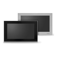
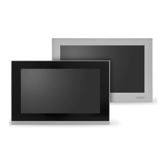
KEB C6 P34 PANEL Instructions For Use Manual (98 pages)
EMBEDDED IPCs
Brand:
KEB
| Category:
Touch Panel
| Size: 9 MB
Table of Contents
Preface
3
Signal Words and Symbols
3
More Symbols
3
Laws and Guidelines
4
Warranty and Liability
4
Support
4
Copyright
4
Table of Contents
5
List of Figures
9
List of Tables
12
Glossary
13
Standards for Control & Automation
14
1 Basic Safety Instructions
16
Target Group
16
Transport, Storage and Proper Use
17
Installation
17
Electrical Connection
18
Start-Up and Operation
18
Maintenance
18
Repair
19
Disposal
19
2 System Description
20
Key Features
20
Supported Operating Systems
20
KEB Standards
20
Front Panel in Different Variants
21
Power Supply with Galvanic Isolation
21
Figure 1: Cut out
21
Figure 2: Isolated Power Supply
21
Key System Identity
22
Fanless
22
LCD LED Backlight
22
Mass Storage
22
Extension Slot & Add-On
22
Figure 3: Non-Volatile Memory
22
Figure 4: Mass Storage
22
Table 1: Expansion Slot & Add-On
22
Package
23
Figure 5: Add-On
23
Figure 6: Package
23
Front Panels
24
Resistive Front Panel
24
Figure 7: Full Aluminium Front Panel Detail
24
Figure 8: Capacitive Front Panel Detail
24
Figure 10: Front Panel „Step" Detail
25
Figure 9: Full Aluminium Front Panel Detail (in the Figure Is Shown as an Example a 15.0" Display)
25
Table 2: Full Aluminium Features
25
Capacitive Front Panel
26
Figure 11: Construction Detail
26
Figure 12: Details Front Panel Capacitive - (in the Figure Is Shown as an Exapmple a 15.6" Display)
26
Figure 13: Capacitive Front Panel „No Step" Detail
27
Figure 14: Features Front Panel Capacitive
27
Figure 15: Construction Detail
27
Figure 16: Fontal USB Detail
28
Figure 17: Fontal USB Detail
28
Front USB 2.0
28
Opening the Cover
28
Figure 18: 4:3 Aspect Ratio Example
29
Figure 19: 5:4 Aspect Ratio Example
29
Figure 20: 16:9 Aspect Ratio Example
29
LCD Aspect Ratio
29
Table 3: LCD Aspect Ratio
29
Rear Panel Areas
30
Figure 21: 16:10 (Wide) Aspect Ratio Example
30
Figure 22: Rear Panel Areas
30
Figure 23: Power Supply Area
31
Figure 24: DC Power Supply Detail
31
Power Supply Area
31
Buttons / Leds Area
32
Figure 25: Buttons / Leds Area
32
Figure 26: Buttons / Leds Area Detail
32
Connectors Area
33
Figure 27: Connectors Area
33
Figure 28: Connectors Area Detail
33
Extension Area
34
Figure 29: Extension Area
34
Figure 30: RVL/LAN Area
34
RVL / LAN Area
34
Micro-UPS
35
Table 4: Micro-UPS Data
35
Figure 31: Label Positions Detail
36
Figure 32: Marking Label Detail
36
KEB Version
36
Marking Label
36
Connectors Label
37
Rear View
37
Figure 33: Connectors Label
37
Figure 34: Rear View
37
Side View
38
Touchscreen
38
Standard Tecnology
38
Figure 35: Side View
38
Figure 36: Standard Tecnology
38
Multi Touch Tecnology
39
Figure 37: Capacitive Front Panel Detail
39
3 Installation and Connection
40
Preparation for Installation
40
Select the Mounting Location
40
Checking the Package Contents
40
Checking the Operating Conditions
40
Mounting Position
40
Damage Due to Overheating
41
Checking Installation Distances
42
Figure 38: Installation Panel Distances
42
Figure 39: Installation Panel Distances
42
Preparing the Mounting Cut-Out
43
Degrees of Protection
43
Figure 40: Inclined Installation
43
Dimensions
44
C6 P34 Panel Resistive
44
Figure 41: C6 P34 Panel Resistive Dimensions
44
Figure 42: C6 P34 Panel Capacitive Dimensions
44
Mounting the Divece (Panel Version)
45
Position of the Mounting Clamps
45
Table 5: Position of the Mounting Clamps
45
Tools to Tighten the Mounting Clamps
46
Prodecure
46
Figure 43: Installation
46
Figure 44: Installation
46
Grounding and Bonding
47
Figure 45: Installation
47
Figure 46: Hex Key Detail
47
Figure 47: Installation
47
Figure 48: Power Supply Diagram
48
Figure 49: Grounding
48
Power Supply Insolation
49
Power Supply Connection
49
Figure 50: Power Supply Connection Detail
49
Power Connector Assembly
50
Figure 51: C6 P34 Panel DC Detail
50
Figure 52: Power Connector Assembly
50
Figure 53: Power Connector Assembly
50
Figure 54: Power Connector Assembly
50
Figure 55: Power Connector Assembly
51
Figure 56: Power Connector Installation
51
Figure 57: Power Connector Installation
51
Figure 58: Power Connector Installation
51
Power on
52
Figure 59: Power Connector Assembly
52
Figure 60: Power on DC
52
Figure 61: Power on DC
53
Figure 62: Power on DC
53
Power Supply LED
54
Front on / off / Standby - Rear on / off / Standby LED
54
Table 6: Power Supply LED
54
4 Operating Systems
55
KEB Windows Images (Windows Embedded Standard 7 / Windows 10)
55
Introduction
55
User Accounts
55
Ethernet Address
55
Table 7: User Accounts
55
Usage of Storage Memories
56
Firewall
57
Egalax Touch Driver
58
Windows Updates
59
Ewf Implementation in the Windows Embedded Standard 7 Images
60
KEB Write Filter Manager (KEB-Wf_Mgr)
60
Introduction
60
How EWF Works
61
Protectable Volumes
61
Keb Ewf Configuration
61
Table 8: Volume Protection
61
Delivery State of EWF on KEB Devices
62
Using Keb_Wf_Mgr
62
Dependent Volumes (Typically E:\)
64
Leave the Keb_Wf_Mgr
65
KEB Uwf Manager
66
Introduction
66
Functioning of the UWF
66
Keb Uwf Configuration And Usage
66
KEB Linux Image
68
Introduction
68
Service User Accounts
68
Change Password for Service User
69
Ethernet IP Address
70
Usage of Storage Memories
70
Common (Windows and Linux)
71
Micro-UPS Handling
71
Ip-Scan
72
Serial Interface
73
5 Mass Storage & Expansions
74
Mass Storage
74
Cfast
74
Figure 63: Cfast Detail
74
Figure 64: Slot for Cfast
74
Figure 65: Cfast
74
SSD Msata
75
Figure 66: SSD Detail
75
Figure 67: SSD Msata
75
6 Maintenance and Service
76
Removing the Rear Cover
76
Figure 68: Removing the Rear Cover
76
Figure 69: Removing the Rear Cover
76
Backup Battery Replacement (Cr2032 3V)
77
Figure 70: Battery Replacement
77
Figure 71: Battery Replacement
77
Ram Installation / Removal
78
Figure 72: Installation / Removal RAM
78
Figure 73: Installation / Removal RAM
78
Figure 74: Installation / Removal RAM
78
Cfast Installation / Removal
79
Installation
79
Figure 75: Cfast Slot Detail
79
Figure 76: Cfast Installation
79
Removal
80
Figure 77: Cfast Removal
80
Figure 78: Cfast Removal
80
Touchscreen
81
Identification Of The Installed Touchscreen
81
Settings for a System with a Resistive Touchscreen
81
Figure 79: Calibration of the Touchscreen
81
Setting of a System with Capacitive Touchscreen
82
Touchscreen Application Tips
82
Use Large Buttons and a Simple Interface
82
Figure 80: Calibration of the Touchscreen
82
Figure 81: Calibration of the Touchscreen
82
Give the User Feedback as Soon as the Screen Is Touched
83
Turn the Cursor off
83
Run Your Application Full Screen
83
Avoid Using a Black Background
83
Maintaining & Cleaning
83
Procedure
83
Recycling and Disposal
83
7 Technical Specifications
84
Block Diagram
84
Figure 82: Block Diagram
84
LCD Characteristics
85
Table 10: LCD Characteristics
85
Table 11: LCD Characteristics
85
Table 9: LCD Characteristics
85
Table 12: LCD Characteristics
86
C6 P34 PANEL Resistive Technical Data
87
Figure 83: C6 P34 PANEL Technical Data
87
C6 P34 PANEL Capacitive Technical Data
88
Figure 84: C6 P34 PANEL Technical Data
88
Figure 85: C6 P34 PANEL Capacitive Technical Specifications
89
Technical Specifications
89
Power Consumption
90
Power Supply Technical Data
90
Battery Technical Data
90
Figure 86: Power Supply Board
90
Figure 87: Battery CR2032 Detail
90
Table 13: Battery Technical Data
90
Dimension Drawings
91
Figure 88: Battery Performance
91
Table 14: Battery Technical Data
91
Table 15: Dimension Drawings
91
Technical Support and Repairs
92
8 Certification
93
Mark of Conformity
93
UL Certifications
95
9 Change History
96
Advertisement
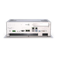
KEB C6 P34 PANEL Instructions For Use Manual (78 pages)
EMBEDDED IPCS
Brand:
KEB
| Category:
Industrial PC
| Size: 13 MB
Table of Contents
Preface
3
Signal Words and Symbols
3
More Symbols
3
Laws and Guidelines
4
Warranty and Liability
4
Support
4
Copyright
4
Table of Contents
5
List of Figures
8
List of Tables
10
Glossary
11
Standards for Control & Automation
12
1 Basic Safety Instructions
14
Target Group
14
Transport, Storage and Proper Use
15
Installation
15
Electrical Connection
16
Start-Up and Operation
16
Maintenance
16
Repair
17
Disposal
17
2 System Description
18
Highlights
18
Supported Operating Systems
18
Power Supply with Galvanic Isolation
19
KEB System Identity
19
Fanless
19
Figure 1: Isolated Power Supply
19
Figure 2: Non-Volatile Memory
19
Mass Storage
20
Expansion Slot & Add-On
20
Figure 3: Mass Storage
20
Figure 4: Expansion Slot Add-On
20
Figure 5: Add-On
20
Package
21
Rear Area
21
Figure 6: Package
21
Figure 7: Connector Details
21
Buttons / Leds Detail
22
Figure 8: Power Supply Detail
22
Figure 9: Buttons / LED Detail
22
Power Supply Detail
22
Connectors Detail
23
Expansion Detail
23
Figure 10: Connectors Detail
23
Figure 11: Expansion Detail
23
Figure 12: Micro-UPS Detail
24
Micro-UPS
24
Table 1: Micro UPS Data
25
The Technical Data for the KEB Micro-UPS
25
Connectors Label
26
Figure 13: Label Position Detail
26
Figure 14: Marking Label Detail
26
Figure 15: Connectors Label Detail
26
Label Position
26
Marking Label
26
Rear View
27
Side View
27
Figure 16: Rear View
27
Figure 17: Side View
27
3 Installation and Connection
28
Preparation for Installation
28
Select the Mounting Location
28
Checking the Package Contents
28
Checking the Operating Conditions
28
Mounting Position
28
Damage Due to Overheating
29
Checking Installation Distances
30
Figure 18: Installation Distances
30
Preparing the Mounting
31
Figure 19: Inclined Installation
31
Dimensions
32
Figure 20: C6 P34 Box Dimensions
32
Mounting the Device
33
Wall Mounting Installation
33
Figure 21: Mounting Installation Detail
33
DIN Guide Installation (Box IPC Only)
34
Figure 22: DIN Guide Installation Detail
34
Figure 23: DIN Guide Installation Detail
34
Grounding and Bonding
35
Figure 24: DIN Guide Installation Detail
35
Figure 25: Power Supply Diagramm
35
Figure 26: Grounding
36
Figure 27: Power Supply Connection Detail
36
Power Supply Isolation
37
Power Supply Connection
37
Power Supply Assembly
37
Figure 28: Power Connector Assembly
37
Figure 29: Power Connector Assembly
37
Figure 30: Power Connector Assembly
38
Figure 31: Power Connector Assembly
38
Figure 32: Power Connector Assembly
38
Figure 33: Power Connector Assembly
38
Power on
39
Figure 34: Power Connector Assembly
39
Figure 35: Power Connector Assembly
39
Figure 36: Power on DC
39
Figure 37: Power on DC
40
Figure 38: Power on DC
40
Power Supply LED
41
Rear On / Off Standby Led
41
Fuse Replacement (Factory Only)
41
Figure 39: Power Supply Detail
41
Table 2: Power Supply LED
41
Table 3: Rear on / off Standby LED
41
4 Operating Systems
42
KEB Windows Images (Windows Embedded Standard 7 / Windows 10)
42
Introduction
42
User Accounts
42
Ethernet Address
42
Table 4: User Accounts
42
Usage of Storage Memories
43
Firewall
44
Egalax Touch Driver
45
Windows Updates
46
Ewf Implementation in the Windows Embedded Standard 7 Images
46
KEB Write Filter Manager (KEB-Wf_Mgr)
47
Introduction
47
How EWF Works
47
Protectable Volumes
48
Keb Ewf Configuration
48
Table 5: Volume Protection
48
Delivery State of EWF on KEB Devices
49
Using Keb_Wf_Mgr
49
Dependent Volumes (Typically E:\)
51
Leave the Keb_Wf_Mgr
52
KEB Uwf Manager
53
Introduction
53
Functioning of the UWF
53
Keb Uwf Configuration And Usage
53
KEB Linux Image
55
Introduction
55
Service User Accounts
55
Change Password for Service User
56
Ethernet IP Address
57
Usage of Storage Memories
57
Common (Windows and Linux)
58
Micro-UPS Handling
58
Ip-Scan
59
Serial Interface
60
5 Mass Storage and Expansions
61
Mass Storage
61
Cfast
61
Figure 40: Cfast Detail
61
Figure 41: Cfast Detail
61
Figure 42: Cfast Slot
61
SSD Msata
62
Figure 44: SSD Slot
62
6 Maintenance and Service
63
Removing the Rear Cover
63
Backup Battery Replacement
63
Figure 45: Removing the Rear Cover
63
Figure 46: Battery Replacement
63
Ram Installation / Removal
64
Figure 47: Battery Replacement
64
Figure 48: RAM Installation / Removal
64
Figure 49: RAM Installation / Removal
64
Fast Installation / Removal
65
Installation
65
Figure 50: RAM Installation / Removal
65
Figure 51: Cfast Slot Detail
65
Figure 52: Cfast Installation
65
Removal
66
Figure 53: Cfast Removal
66
Figure 54: Cfast Removal
66
7 Technical Specifications
67
Block Diagram
67
Technical Data
67
Options
67
Figure 55: Block Diagram
67
Table 6: C6 P34 Box - Technical Data
67
Table 7: C6 P34 Box - Options
67
Technical Specifications
68
Table 8: Technical Data
68
Power Consumption
69
Power Supply Technical Data
69
Figure 56: Power Supply Board
69
Table 9: Power Supply Technical Data
69
System Power Consumption
70
Table 10: System Power Consumption
70
Battery Technical Data
71
Figure 57: Battery CR2032 Detail
71
Figure 58: Battery Performance
71
Figure 59: Battery Dimensions
71
Table 11: Battery Technical Data
71
Technical Support and Repairs
72
8 Certification
73
Mark of Conformity
73
UL Marking
75
Advertisement
Related Products
KEB C6 E22 BM-RVL
KEB C6 P34 BOX Series
KEB C6 P3 Series
KEB C6 P33
KEB C6-COMPACT II
KEB C6 HMI LC
KEB C6 E1-ET
KEB C6 E2-ET
KEB C6 E2
KEB C6 L4
KEB Categories
DC Drives
Controller
Inverter
Control Unit
Industrial Equipment
More KEB Manuals
Login
Sign In
OR
Sign in with Facebook
Sign in with Google
Upload manual
Upload from disk
Upload from URL