Sign In
Upload
Manuals
Brands
KAESER Manuals
Control Unit
SIGMA CONTROL 2
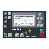
User Manuals: KAESER SIGMA CONTROL 2 Compressor System
Manuals and User Guides for KAESER SIGMA CONTROL 2 Compressor System. We have
2
KAESER SIGMA CONTROL 2 Compressor System manuals available for free PDF download: User Manual, Service Manual
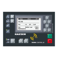
KAESER SIGMA CONTROL 2 User Manual (246 pages)
Brand:
KAESER
| Category:
Controller
| Size: 5 MB
Table of Contents
Table of Contents
3
SIGMA CONTROL 2 Quick Reference Guide
11
Operating Elements
11
Fig. 1 Operating Elements
11
Display Elements
12
Fig. 2 Display Elements
12
Tab. 2 Display Elements
12
Main Menu Overview
13
Functions Overview
13
Tab. 3 Main Menu Overview
13
Tab. 4 Functions Overview
14
Regarding this Document Using this Document
16
Copyright
16
Software
16
Certification
17
Updating the User Manual
17
Symbols and Labels
17
Warnings
17
Potential Damage Warnings
18
Tab. 5 Danger Levels and Their Definition (Personal Injury)
18
Tab. 6 Danger Levels and Their Definition (Damage to Property)
18
Other Alert Notes and Their Symbols
19
Tab. 7 Formatting Options
19
Technical Data Controller SIGMA CONTROL
20
Versions and Options
20
User Interface with Display, CPU and Interfaces
20
Tab. 8 Versions and Options
20
Tab. 9 User Interface
20
Fig. 3 MCS Interfaces
21
Tab. 10 Display Data
21
Tab. 11 MCS Interfaces
21
Fig. 4 MCSIO Interfaces
22
Tab. 12 MCSIO Interfaces
22
Inputs and Outputs with MCSIO
23
Input/Output Modules
23
Tab. 13 RFID
23
Tab. 14 Inputs and Outputs with MCSIO
23
Tab. 15 Maximum Cable Lengths
23
Tab. 16 IOM-1
24
Tab. 17 IOM-2
24
Tab. 18 IOM-3
24
Sensors
25
Tab. 19 Power Supply Specifications
25
Tab. 20 Maximum Cable Lengths
25
Tab. 21 Degree of Protection, IOM
25
Tab. 22 IOM Dimensions
25
Tab. 23 Pressure Transducer
26
Tab. 24 Resistance Thermometer
26
Safety and Responsibility Basic Instructions
27
Specified Use
27
Improper Use
27
Design and Function
28
Controller Overview
28
Fig. 5 MCS System Design with IOM
29
Fig. 6 MCSIO System Design
29
Operating Panel
30
Operating Elements
30
Fig. 7 Operating Elements
30
Display Elements
31
Fig. 8 Display Elements
31
RFID Reader
32
Display
32
Fig. 9 RFID Reader
32
Tab. 26 Display Elements
32
Tab. 27 RFID Reader
32
Operating Mode
33
Tab. 28 Data in the Header Depending on the Machine Type
33
Main Menu
34
Setting Parameters
34
Activating Keys with Check Boxes
35
Access Control
35
Tab. 29 Reset Check Box Status
35
Tab. 30 Check Box Status
35
Kaeser Connect
36
Fig. 10 KAESER CONNECT for SIGMA CONTROL
36
Menu Overview
37
Operating Mode
37
Tab. 31 KAESER CONNECT Functions
37
Menu Structure
38
Tab. 32 Menu Structure of Main Menu
41
Tab. 33 Status Menu
43
Tab. 34 Configuration Menu
47
Tab. 35 Pressure Control Menu
48
Tab. 36 I/O Periphery Menu
51
Tab. 37 Communication Menu
53
Tab. 38 Connections Menu
53
Tab. 39 Components Menu
54
Tab. 40 Power Switching Menu
56
Operating Modes and Control Modes
57
Machine Operating Modes
57
Control Modes
57
Variable Speed Drive with Frequency Converter (SFC)
59
MODULATING Control
60
Installation and Operating Conditions
61
Maintaining Ambient Conditions
61
Installation Conditions
61
Installation
62
Reporting Transport Damage
62
Machine Identification
62
Tab. 41 Machine Identification
62
Tab. 42 Remote Control Identification
62
Tab. 43 Machine Identification
62
Initial Start-Up Outline
63
Setting the Controller
63
Selecting Menu Options
64
Setting the Language
65
Tab. 44 Supported Languages
65
Noting the User Name
66
User Log-On with RFID Equipment Card
67
Fig. 11 Back of the RFID Equipment Card
67
Fig. 12 User Log-In with RFID Equipment Card
67
Generating a Password
68
Fig. 13 User Log-In with RFID Equipment Card
68
Manual User Log-In
69
Create the Master RFID Equipment Card
70
Fig. 14 Manual User Log-On
70
Checking/Setting Time and Date
71
Set the Time Zone
73
Set Display Formats
73
Tab. 45 Date Formats
73
Tab. 46 Possible Settings for the Time Format
74
Tab. 47 Possible Settings for the Pressure Unit
75
Setting the Display Illumination
76
Setting the Contrast and the Brightness
77
Activating the Remote Control
77
IP Configuration
78
Tab. 50 Network Parameters
79
Setting the E-Mail Function
80
Configuring the Time Server
82
Using KAESER CONNECT
83
Open KAESER CONNECT
83
Fig. 15 Login Window
84
Fig. 16 KAESER CONNECT for SIGMA CONTROL
84
System Status Menu
85
Fig. 17 Select Language: Window
85
Fig. 18 System Status Menu
85
Graphs Menu
86
Fig. 19 Main Menu
86
Fig. 20 Graphs (Illustration Similar)
87
Fig. 21 Arrow Keys
87
Tab. 52 Arrow Key Functions
87
Messages Menu
88
I/O Display Menu
89
Fig. 22 Messages
89
User Management Menu
90
Fig. 23 I/O Display (Illustration Similar)
90
Fig. 24 User Management Menu
91
Fig. 25 Log on for Write Access: Window
91
Fig. 26 User Management Menu
92
Settings
93
Fig. 27 Settings
93
Backup Menu
94
Data Recording Menu
94
Fig. 28 Backup Menu
94
Closing KAESER CONNECT
95
Fig. 29 Data Recording Menu
95
Adjusting the Pressure Parameters of the Machine
96
Displaying Pressure Parameters
97
Setting Pressure Parameters
98
Tab. 54 Setting Limits for the Network Nominal Pressure (* Cut-In Pressure Min)
98
Tab. 55 Pressure Condition for LOAD
98
Tab. 56 Pressure Conditions for IDLE
98
Activating/Deactivating the "LOAD/IDLE" Key
100
Configuring Machine Start and Stop
101
Automatic Start/Stop in Timer Mode
101
Tab. 59 Configuring Machine Start and Stop
101
Tab. 60 User-Defined Clock Program Machine ON/OFF
102
Setting up the Company Shut-Down
105
Controlling the Machine Remotely (Remote ON/OFF)
106
Activating the Remote Control
108
Activating/Deactivating the Idle Period "Venting Period" Function
109
Autostart" Function
109
Tab. 62 Autostart Delay Time
111
Control Modes
112
Setting the Control Mode
112
Setting the DUAL Control Mode
113
Setting the QUADRO Control Mode
114
Electronic Thermal Management
115
Tab. 63 Machine Type and ETM Design
115
Activating Heat Recovery for Machine Type 2
116
Activating Heat Recovery for Machine Type 3
117
Deactivating Heat Recovery
119
Refrigerated Dryer
119
Setting the Operating Mode
119
Output Messages
120
Refrigerated Dryer Alarm - Compressed Air Quality Has Priority
122
Refrigerated Dryer Alarm - Compressed Air Supply Has Priority
123
Setting the Machine for Local Mode
123
Menu Load Control
124
Setting the Nominal Pressure Change Via Timing Program
124
Tab. 64 Operating Modes in Local Operating Mode (Local Mode)
124
Setting the Nominal Pressure Change Via Timer
127
Configuring the Machine for Master Control
129
Overview of the Different Master Operating Modes
129
SAM 4.0 Mode
130
Tab. 67 Master Control (Interconnected Operation) - Overview
130
Configuring PROFIBUS Mode (SIGMA AIR MANAGER)
133
Tab. 68 Parameters for Monitoring for Communication Malfunction
133
Fig. 30 PROFIBUS Plug Wiring
134
Tab. 69 Pin Assignment of SUB-D 9-Pole Interface on the PROFIBUS Module
134
Fig. 31 Electrical Diagram Example with SIGMA AIR MANAGER
135
Fig. 32 Communication Interface
136
Fig. 33 Insert the Communication Module
137
Fig. 34 Front Plate Communication Module PROFIBUS
138
Interconnection of Two Machines in Master/Slave Operation
141
Tab. 70 Master-Slave Settings
142
Fig. 35 Direct Connection of Two SIGMA CONTROL 2
143
Configuring Master Control Using the LOAD Remote Contact (E.g. SIGMA AIR MANAGER BASIC)
148
Fig. 36 LOAD Remote Contact
149
Setting the Master Control with Local/Load Remote Contact
150
Fig. 37 Wiring Diagram for Local/Load Remote Contact
151
Setting the Setpoint Pressure Pre-Selection Via Remote Contact
154
Master Control for Machines Regulated by Pressure Switch
155
Fig. 38 Machine with Pressure Switch Regulation
156
Fig. 39 Function Diagram
159
Tab. 71 Function Diagram
159
Examples of Time Settings for Equal Overall Load
160
Setting Input and Output Signals
161
Output Important Operational States of Machine on Digital Outputs
161
Tab. 73 Example for a Clock Program for Equal Duty Cycling During the Week
161
Tab. 74 Assigned Output Signals
162
Output Input Signals on the Display
163
Tab. 75 Logic Settings
166
Output Measured Values on the Display
167
Tab. 76 Assigned Analog Measured Values
168
Switching And/Or Triggering Messages with Thresholds
173
Timer
177
Activating Remote Acknowledgement
178
Setting the Remote Acknowledgement Function
179
Activating the Remote Control
179
Assigning an Input
180
Linking to an External Pressure Transducer
181
Pressure Control Menu
181
Assigning an Input to an External Pressure Transducer
181
Tab. 78 Transmitting a Pressure Transducer Value
181
Commissioning the Machine
182
Tab. 79 Check List for Commissioning the Machine
182
Operation
184
Switching on and off
184
Switching on
184
Fig. 40 Switching the Compressed Air Station on and off
184
Switching off
185
Switching off in an Emergency
185
Fig. 41 Switching off in an Emergency
185
Acknowledging Alarm and Warning Messages
186
Fig. 42 Acknowledging Messages
186
Displaying Messages
187
Selecting the Status Menu
188
Tab. 82 Information of a Message
188
Tab. 83 Message Abbreviations
188
Displaying the Current Operating Mode
190
Tab. 84 Operating Mode Display
190
Tab. 85 Abbreviation of Operating Modes
190
Adjusting the Working Pressure
191
Displaying Analogue Data
191
Displaying Operating Data
192
Checking the Operating Hours
192
Checking the Switching Cycles
193
Displaying the Frequency Converter Settings
194
Setting the Maintenance Interval
195
Resetting the Maintenance Interval Counter
196
External Maintenance Counter
197
Safety Relief Valve Test
200
Tab. 86 Check Box Status
200
Excessive Temperature Shut-Down Test
203
Save Data
204
Format SD Card
206
10 Fault Recognition and Rectification
207
Basic Information
207
Interpreting Fault Messages
207
Interpreting Warning Messages
216
Tab. 87 Alarm Messages, Possible Causes and Remedies
216
Tab. 88 Warning Messages and Remedies
236
Interpreting Operating Messages
237
Interpreting Diagnostic Messages
240
Interpreting System Messages
240
Tab. 89 Operating Messages
240
Tab. 90 System Messages and Remedies
241
11 Maintenance
242
Replacing the Battery
242
12 Spares, Operating Materials, Service
243
Note the Nameplate
243
Service Addresses
243
Displaying the Version Number, Machine Model, Part Number and Serial Number
243
13 Decommissioning, Storage and Transport
245
Commissioning
245
Packing
245
Storage
245
Transporting
245
Battery Removal and Disposal
245
Advertisement
KAESER SIGMA CONTROL 2 Service Manual (184 pages)
Brand:
KAESER
| Category:
Control Unit
| Size: 4 MB
Table of Contents
Table of Contents
3
1 SIGMA CONTROL 2 Quick Installation Guide
11
Operating Elements
11
Fig. 1 Operating Elements
11
Tab. 1 Operating Elements
11
Display Elements
12
Main Menu - Overview
12
Fig. 2 Display Elements
12
Tab. 2 Display Elements
12
Functions - Overview
13
Tab. 3 Main Menu - Overview
13
Tab. 11 RFID
13
Tab. 4 Functions - Overview
14
2 Regarding this Document Using this Document
15
Copyright
15
Software
15
Certification
16
Updating the Operating Manual
16
Symbols and Labels
16
Warnings
16
Potential Damage Warnings
17
Tab. 5 Danger Levels and Their Definition (Personal Injury)
17
Tab. 6 Danger Levels and Their Definition (Damage to Property)
17
Other Alert Notes and Their Symbols
18
Tab. 7 Formatting Options
18
3 Technical Specifications 3.1 Controller SIGMA CONTROL 2
19
User Interface with Display, CPU and Interfaces
19
Tab. 8 User Interface
19
Tab. 9 Display Data
19
Fig. 3 MCS Interfaces
20
Input/Output Module
21
Tab. 12 IOM
21
Tab. 13 Power Supply Specifications
21
Tab. 14 Cable Lengths
21
Sensors
22
Communication Modules
22
Tab. 15 Degree of Protection, IOM
22
Tab. 16 IOM Dimensions
22
Tab. 17 Pressure Transducer
22
Tab. 18 Resistance Thermometer
22
Modbus Module
23
PROFIBUS Module
23
Tab. 19 Technical Specifications - PROFIBUS
23
Tab. 20 Assignment of PROFIBUS Interface
23
Modbus TCP Module
24
Tab. 21 Technical Specifications - SIGMA CONTROL 2 Interface
24
Tab. 22 Assignment of the SIGMA CONTROL 2 Interface
24
Devicenet Module
25
Tab. 23 Technical Specifications - Modbus TCP Interface
25
Tab. 24 Assignment of the Modbus TCP Interface
25
Tab. 25 Recommended Conductors - Modbus TCP Interface
25
Tab. 26 Technical Specifications - SIGMA CONTROL 2 Communication Module
25
PROFINET Module
26
Tab. 27 Assignment of the SIGMA CONTROL 2 Interface
26
Tab. 28 Technical Specifications - SIGMA CONTROL 2 Interface
26
Ethernet/Ip-Module
27
Tab. 29 Assignment of the SIGMA CONTROL 2 Interface
27
Tab. 30 Recommended Conductors - SIGMA CONTROL 2 Interface
27
Tab. 31 Technical Data Ethernet/Ip-Interface
27
Tab. 32 Configuration of the Ethernet/Ip-Interface
28
Tab. 33 Ethernet/Ip-Interface - Cabling Recommendation
28
4 Safety and Responsibility Basic Instructions
29
Specified Use
29
Improper Use
29
5 Design and Function
30
STC and OFC/SFC Machine Types
30
The Controller
30
Fig. 4 System Structure
31
Operating Panel
32
Operating Elements
32
Fig. 5 Operating Elements
32
Tab. 34 Operating Elements
32
Display Elements
33
RFID Reader
33
Fig. 6 Display Elements
33
Tab. 35 Display Elements
33
Display
34
Fig. 7 RFID Reader
34
Tab. 36 RFID Reader
34
Fig. 10 Operating Mode
35
Fig. 11 Operating Mode
35
Fig. 8 Operating Mode
35
Operating Mode
35
Main Menu
36
Setting Parameters
36
Activating Keys with Check Boxes
37
Access Rights
37
Tab. 37 Reset Check Box Status
37
Tab. 38 Check Box Status
37
Kaeser Connect
38
Fig. 9 KAESER CONNECT for SIGMA CONTROL
38
Menu Overview
39
Operating Mode
39
Tab. 39 KAESER CONNECT Functions
39
Menu Structure
40
Tab. 40 Menu Structure of Main Menu
43
Tab. 41 Status Menu
44
Tab. 42 Configuration Menu
46
Tab. 43 Communication Menu
47
Tab. 44 Connections Menu
48
Control Modes
51
Ready Control Mode
51
Tab. 45 Components Menu
51
Operating Control
52
Tab. 46 SIGMA CONTROL 2 Ready States
52
6 Installation and Operating Conditions
56
Maintaining Ambient Conditions
56
Installation Conditions
56
7 Installation
57
Reporting Transport Damage
57
Machine Identification
57
Tab. 47 Machine Identification
57
Tab. 48 Remote Control Identification
57
Tab. 49 Machine Identification
57
8 Initial Start-Up Outline
58
Setting the Controller
58
Selecting Menu Options
59
Setting the Language
60
Noting the User Name
61
User Log-On with RFID Equipment Card
61
Fig. 12 Back of the RFID Equipment Card
61
Fig. 13 User Log-On with RFID Equipment Card
61
Generating a Password
62
Fig. 14 User Log-In with RFID Equipment Card
62
Manual User Log-On
63
Create the Master RFID Equipment Card
64
Fig. 15 Manual User Log-On
64
Checking/Setting Time and Date
65
Set the Time Zone
67
Set Display Formats
67
Tab. 51 Date Formats
67
Tab. 52 Possible Settings for the Time Format
68
Tab. 53 Possible Settings for the Pressure Unit
69
Setting the Display Illumination
70
Setting the Contrast and the Brightness
71
Activating the Remote Control
71
IP Configuration
72
Tab. 56 Network Parameters
73
Setting the E-Mail Function
74
Setting the Time Server
76
KAESER CONNECT Benefits
77
Open KAESER CONNECT
78
Fig. 16 Log-In Mask
78
System Status Menu
79
Fig. 17 KAESER CONNECT for SIGMA CONTROL
79
Fig. 18 Select Language: Window
79
Fig. 19 System Status Menu
80
Fig. 20 Main Menu
80
Graphs Menu
81
Fig. 21 Graphs (Illustration Similar)
81
Fig. 22 Control Keys
82
Tab. 58 Control Key Functions
82
Messages Menu
83
I/O Display Menu
83
Fig. 23 Messages (Illustration Similar)
83
User Management Menu
84
Fig. 24 I/O Display (Illustration Similar)
84
Fig. 25 User Management Menu
85
Fig. 26 Log on for Write Access: Window
85
Fig. 27 User Management Menu
86
Settings Menu
87
Fig. 28 Settings Menu
87
Save Data Menu
88
Data Recording Menu
88
Fig. 29 Backup Menu
88
KAESER CONNECT Exit
89
Fig. 30 Data Recording Menu
89
Displaying and Setting the Blower Properties
90
Displaying the Blower Properties
90
Setting the Installation Elevation
90
Tab. 59 Blower Characteristics
90
Machine Start and Machine Stop
91
Automatic Start/Stop in Timer Mode
91
Tab. 61 User-Defined Clock Programme Machine ON/OFF
92
Tab. 62 Example of a Machine ON/OFF Clock Program
93
Automatic Start/Stop with Timer
95
Automatic Restart" Function
96
Tab. 63 Delay Time for Automatic Restart
97
Controlling Machine from a Remote Location
98
Operating Modes in Frequency-Controlled Machines
101
Current Signal AII1.02
102
Setting the Operating Mode
103
Constant Speed
104
Pressure Control
105
External Speed Definition
108
Control with External Variable
109
SFC Acceleration Time
112
Setting the Machine for Master Control Operation
112
Overview of the Different Master Operating Modes
112
SAM 4.0 Mode
113
Tab. 64 Overview of the Different Master Controllers
113
Master Control Via Communication Module
116
Tab. 65 Parameters for Monitoring for Communication Malfunction
116
Tab. 66 Setting the Starttd Parameter
117
Tab. 67 Setting the Timeout Parameter
118
Tab. 68 Setting the Starttd Parameter
119
Tab. 69 Setting the Timeout Parameter
119
Tab. 70 Setting the Starttd Parameter
120
Tab. 71 Setting the Timeout Parameter
120
Tab. 72 Setting the Starttd Parameter
121
Tab. 73 Setting the Timeout Parameter
122
Tab. 74 Setting the Starttd Parameter
123
Tab. 75 Setting the Timeout Parameter
123
Tab. 76 Setting the Starttd Parameter
124
Tab. 77 Setting the Timeout Parameter
124
Master Control of Two Machines in Master/Slave Operation
125
Tab. 78 Master-Slave Settings
125
Fig. 31 Direct Connection of Two SIGMA CONTROL 2
126
Setting Input and Output Signals
130
Output Operational States of Machine on Digital Outputs
130
Tab. 79 Assigned Output Signals
130
Output Input Signals on the Display
131
Tab. 80 Logic Settings
134
Switching And/Or Triggering Messages with Thresholds
136
Tab. 81 Available Measured Values
136
Activating Remote Acknowledgement
140
Setting the Remote Acknowledgement Function
140
Error Behaviour
141
Commissioning the Machine
142
Tab. 82 Check List for Starting the Machine
142
Fig. 32 Operating Mode
143
9 Operation
144
Switching the Machine on and off
144
Switching on
144
Fig. 33 Switching the Compressed Air Station on and off
144
Tab. 83 Maximum Permissible Number of Motor Starts Per Hour
144
Switching off
145
Switching off in an Emergency
145
Fig. 34 Switching off in an Emergency
145
Acknowledging Alarm and Warning Messages
146
Fig. 35 Acknowledging Messages
146
Displaying Messages
147
Status - Messages Menu
148
Tab. 87 Message Abbreviations
148
Displaying Analogue Data
150
Displaying Operating Data
151
Setting the Maintenance Interval
153
Communication Modules
153
Displays at the PROFIBUS Module
153
Display at the Modbus Module
154
Fig. 36 PROFIBUS Communication Module - Leds and Interface
154
Fig. 37 Modbus Communication Module - Leds and Interface
154
Tab. 88 PROFIBUS Communication Module - Interpretation of Leds
154
Displays at the Modbus TCP Module
155
Fig. 38 Modbus TCP Communication Module - Leds and Interface
155
Tab. 89 Modbus Communications Module - Interpretation of Leds
155
Display at the Devicenet Module
156
Displays at the PROFINET Module
156
Fig. 39 Devicenet Communication Module - Leds and Interface
156
Tab. 90 Modbus TCP Communications Module - Interpretation of Leds
156
Tab. 91 Devicenet Communications Module - Interpretation of Leds
156
Fig. 40 PROFINET Communication Module - Leds and Interface
157
Tab. 92 PROFINET Communications Module - Interpretation of Leds
157
Displays at the Ethernet/Ip-Module
158
Save Data
158
Fig. 41 Ethernet/Ip Communication Module - Leds and Interface
158
Tab. 93 Ethernet/Ip Communication Module - Interpretation of Leds
158
Format SD Card
160
10 Fault Recognition and Rectification
161
Basic Instructions
161
Interpreting Fault Messages
161
Interpreting Warning Messages
165
Tab. 94 Fault Messages and Remedies
165
Interpreting Operation Messages
170
Tab. 96 Operational Messages
171
Interpreting Diagnostic Messages
172
Interpreting System Messages
172
Communication Modules
172
Troubleshooting, PROFIBUS Module
172
Troubleshooting at the Modbus Module
173
Troubleshooting Modbus Tcp/Ethernet IP-Module
174
Troubleshooting at the Devicenet Module
175
Tab. 103 Fault Displays in the Communication - Com-Module Menu
175
Tab. 104 Com-Module Communication Error Warning Message
175
Tab. 105 Fault Indications at the Devicenet Communication Module
176
Troubleshooting, PROFINET Module
177
Tab. 106 Fault Displays in the Communication - Com-Module Menu
177
Tab. 107 Com-Module Communication Error Warning Message
177
11 Maintenance
179
Changing the Battery
179
12 Spares, Operating Materials, Service
180
Note the Nameplate
180
Kaeser Air Service
180
Displaying the Version Number, Machine Model, Material Number and Serial Number
180
Fig. 42 Battery Labelling
184
Advertisement
Related Products
KAESER ECO-DRAIN 21
KAESER ECO-DRAIN 21 PLUS
KAESER KPF-RF 2500
KAESER KPF-RF 21250
KAESER KPF-RF 2805HP
KAESER KPF-RF 20695HP
KAESER KPF-RF 26340HP
KAESER KPF-RF 28380HP
KAESER 2200
KAESER 2600
KAESER Categories
Air Compressor
Dryer
Compressor
Water Filtration Systems
Dehumidifier
More KAESER Manuals
Login
Sign In
OR
Sign in with Facebook
Sign in with Google
Upload manual
Upload from disk
Upload from URL