
Related Manuals for KAESER SIGMA CONTROL 2


Summary of Contents for KAESER SIGMA CONTROL 2
- Page 1 User Manual Controller SIGMA CONTROL 2 SCREW FLUID ≥5.1.2 No.: 9_9450 13 USE Manufacturer: KAESER KOMPRESSOREN SE 96410 Coburg • PO Box 2143 • GERMANY • Tel. +49-(0)9561-6400 • Fax +49-(0)9561-640130 www.kaeser.com...
- Page 2 /KKW/SSC 2.13 en Z1 IBA-SIGMA CONTROL FLUID O.IBOX /KKW/SSC 2.13 Z1 20220413 060836...
-
Page 3: Table Of Contents
Contents SIGMA CONTROL 2 Quick reference guide Operating elements ......................Display elements ......................Main menu overview ......................Functions overview ......................Regarding this Document Using this document ......................Copyright .......................... 2.2.1 Software ......................Certification ........................Updating the user manual ....................Symbols and labels ...................... - Page 4 8.7.2 Activating heat recovery for machine type 3 ............107 8.7.3 Deactivating heat recovery ................. 109 Refrigerated dryer ......................109 8.8.1 Setting the operating mode ................. 109 User Manual Controller SIGMA CONTROL 2 SCREW FLUID ≥5.1.2 No.: 9_9450 13 USE...
- Page 5 9.12 External maintenance counter ..................9.13 Safety relief valve test ..................... 190 9.14 Excessive temperature shut-down test ................193 9.15 Save data ......................... 194 9.15.1 Format SD card ....................User Manual Controller No.: 9_9450 13 USE SIGMA CONTROL 2 SCREW FLUID ≥5.1.2...
- Page 6 12.3 Displaying the version number, machine model, part number and serial number ... 233 Decommissioning, Storage and Transport 13.1 De-commissioning ......................235 13.2 Packing ..........................13.3 Storage ..........................235 13.4 Transporting ........................235 13.5 Battery removal and disposal ................... 235 User Manual Controller SIGMA CONTROL 2 SCREW FLUID ≥5.1.2 No.: 9_9450 13 USE...
- Page 7 Insert the communication module....................Fig. 34 Front plate communication module PROFIBUS ................. 128 Fig. 35 Direct connection of two SIGMA CONTROL 2 ................133 Fig. 36 LOAD remote contact ......................... 139 Fig. 37 Wiring diagram for local/LOAD remote contact: ................. 141 Fig.
- Page 8 List of Illustrations User Manual Controller SIGMA CONTROL 2 SCREW FLUID ≥5.1.2 No.: 9_9450 13 USE...
- Page 9 E-mail parameters ........................Tab. 52 Arrow key functions ........................Tab. 53 Compressor pressure parameters ....................Tab. 54 Setting limits for the network nominal pressure (* Cut-in pressure min) ........User Manual Controller No.: 9_9450 13 USE SIGMA CONTROL 2 SCREW FLUID ≥5.1.2...
- Page 10 Alarm messages, possible causes and remedies ..............197 Tab. 88 Warning messages and remedies ....................207 Tab. 89 Operating messages ........................227 Tab. 90 System messages and remedies ....................230 User Manual Controller viii SIGMA CONTROL 2 SCREW FLUID ≥5.1.2 No.: 9_9450 13 USE...
-
Page 11: Sigma Control 2 Quick Reference Guide
SIGMA CONTROL 2 Quick reference guide Operating elements 1 SIGMA CONTROL 2 Quick reference guide Operating elements Fig. 1 Operating elements Item Designation Function «Up» Scrolls the menu up. Increases a parameter value. «Left» Moves to the left. Moves the cursor position to the left. -
Page 12: Display Elements
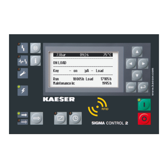
SIGMA CONTROL 2 Quick reference guide Display elements Display elements Fig. 2 Display elements Item Designation Function Indicator illuminates in green when the machine is switched on. Display Graphic display with 8 lines and 30 characters per line. Timer control Illuminates continuously in green when the machine is controlled by the timer. -
Page 13: Main Menu Overview
SIGMA CONTROL 2 Quick reference guide Main menu overview Main menu overview Press «Up» / «Down» / «Enter» to open the main menu. Menu no. Menu name Function Status Displays messages, statistics and status information Performance data Displays measured data from the machine and its components (e.g. -
Page 14: Tab. 4 Functions Overview
SIGMA CONTROL 2 Quick reference guide Functions overview Function Menu Action steps Chapter Activate – Activate the «Timer control» key – Press the «Timer control» 8.5.1.4 «Timer control» <Configuration – Compressor start – Compressor on – Key Activate 5.2.3 8.2.13 remote –... - Page 15 SIGMA CONTROL 2 Quick reference guide Functions overview Settings can be entered following log-in with an RFID Equipment Card providing password access level 2. User Manual Controller No.: 9_9450 13 USE SIGMA CONTROL 2 SCREW FLUID ≥5.1.2...
-
Page 16: Regarding This Document Using This Document
The user manual contains important information to the entire life cycle of SIGMA CONTROL 2. The user manual is a component of the product. ➤ Keep the user manual in a safe place throughout the life of SIGMA CONTROL 2. ➤ Pass the user manual on to the next owner/user of the machine. -
Page 17: Certification
(for example: when connecting to computers or peripheral equipment use shielded cables on‐ ly). Updating the user manual The page http://www.kaeser.com/int-en/manuals/response.aspx of our website provides frequently updated versions of this user manual. ➤ Download the user manual in your language. -
Page 18: Potential Damage Warnings
Potential effects when ignoring the warning are indicated here. ➤ The protective measures against the damages are shown here. ➤ Carefully read and fully comply with warnings against damages. User Manual Controller SIGMA CONTROL 2 SCREW FLUID ≥5.1.2 No.: 9_9450 13 USE... -
Page 19: Other Alert Notes And Their Symbols
➤ ... as is a solution. This symbol identifies important information or measures regarding the protection of the envi‐ ronment. Further information Further subjects are introduced here. User Manual Controller No.: 9_9450 13 USE SIGMA CONTROL 2 SCREW FLUID ≥5.1.2... -
Page 20: Technical Data Controller Sigma Control
Battery service life: more than 10 years ─ Battery replaceable 3.1.1 Versions and options SIGMA CONTROL 2 is offered in different designs. Type Prepared for connection to control center Connection to control technology not provided Option Components Main Control System (MCS): Slot for an Main Control System Input Output optional communication module (to con‐... -
Page 21: Fig. 3 Mcs Interfaces
SD card, SD card slot SD/SDHC card Functional ground (FG) The positions of the interfaces X1–X6 are marked on the rear of the controller. Tab. 11 MCS interfaces User Manual Controller No.: 9_9450 13 USE SIGMA CONTROL 2 SCREW FLUID ≥5.1.2... -
Page 22: Fig. 4 Mcsio Interfaces
The positions of the interfaces X1–X10 are marked on the rear of the controller. Tab. 12 MCSIO interfaces Identification with RFID Equipment Card Feature Value Hardware on the SIGMA CONTROL 2 controller RFID write/read device Hardware (external) RFID Equipment Card Recognition distance [in.] Max. 2... -
Page 23: Inputs And Outputs With Mcsio
Refer to the machine's wiring diagram for the input/output modules installed in your equipment. Every input/output module is equipped with: ■ Internal temperature monitoring ■ Internal low voltage monitoring ■ LED indication of operational status User Manual Controller No.: 9_9450 13 USE SIGMA CONTROL 2 SCREW FLUID ≥5.1.2... -
Page 24: Tab. 16 Iom-1
Digital output relay (DOR), 250 VAC, 8 A – – Digital output transistor (DOT), 24 VDC, 0.5 A – Analog output current (AOI), 0–20 mA – – Tab. 18 IOM-3 User Manual Controller SIGMA CONTROL 2 SCREW FLUID ≥5.1.2 No.: 9_9450 13 USE... -
Page 25: Sensors
Power is provided by the machine's power supply unit. Feature Value Rated power supply (stabilized) [V DC] Current consump‐ tion SIGMA CONTROL 2 with IOM 1 [A] Current consumption IOM 2 [A] Current consumption IOM 3 [A] IOM ≙ Input/Output module Tab. 19 Power supply specifications 3.1.4.2... -
Page 26: Tab. 23 Pressure Transducer
Controller SIGMA CONTROL 2 Feature Value Connection Twin cable Tab. 23 Pressure transducer Resistance thermometer Feature Value Sensing resistance Pt100 Connection Twin cable Tab. 24 Resistance thermometer User Manual Controller SIGMA CONTROL 2 SCREW FLUID ≥5.1.2 No.: 9_9450 13 USE... -
Page 27: Safety And Responsibility Basic Instructions
The safety regulations of the machine in which SIGMA CONTROL 2 is installed apply. Specified use SIGMA CONTROL 2 is solely intended for the control of machines in which SIGMA CONTROL 2 is factory-installed. Any other use is considered incorrect. The manufacturer is not liable for any dam‐... -
Page 28: Design And Function
─ Without slot for customer interface ■ Input-Output-Module (IOM): For SIGMA CONTROL 2 (Prepared for connection to control center): modules with digital and analog inputs and outputs with autonomous power supply. User Manual Controller SIGMA CONTROL 2 SCREW FLUID ≥5.1.2... -
Page 29: Fig. 5 Mcs System Design With Iom
MCS system design with IOM Machine enclosure Inputs/outputs in the interior of the control Control cabinet cabinet SIGMA CONTROL 2 (Prepared for con‐ Inputs/outputs in the interior of the com‐ nection to control center) pressor Input-Output-Module (IOM): Inputs/outputs for external sensors... -
Page 30: Operating Panel
Exits editing mode and saves. «ON» Switches the machine on. «OFF» Switches the machine off. RFID RFID reader for user log-in via RFID Equipment Card. not on AIRTOWER User Manual Controller SIGMA CONTROL 2 SCREW FLUID ≥5.1.2 No.: 9_9450 13 USE... -
Page 31: Display Elements
Illuminates continuously in green when the machine is running in LOAD. Controller voltage Illuminates continuously in green when voltage is supplied to the con‐ troller. not on AIRTOWER User Manual Controller No.: 9_9450 13 USE SIGMA CONTROL 2 SCREW FLUID ≥5.1.2... -
Page 32: Rfid Reader
Placing a suitable transponder in front of the RFID reader of the controller will automatically acti‐ vate the communication between transponder and SIGMA CONTROL 2. A suitable transponder is the RFID Equipment Card. Two of them have been provided with the ma‐... -
Page 33: Operating Mode
Depending on the settings, either the current state of the machine or a menu text is shown in line 3. The following parameters with their current values are displayed in line 5: ■ Remote control yes/no ■ Timer control yes/no ■ Pressure control User Manual Controller No.: 9_9450 13 USE SIGMA CONTROL 2 SCREW FLUID ≥5.1.2... -
Page 34: Main Menu
In order to set a parameter in the active line of the selected menu, you must always switch to setting mode. Setting parameters Press «Enter». The value of the parameter will flash indicating that it can be changed. User Manual Controller SIGMA CONTROL 2 SCREW FLUID ≥5.1.2 No.: 9_9450 13 USE... -
Page 35: Activating Keys With Check Boxes
5.3.4 Activating keys with check boxes Certain keys of the SIGMA CONTROL 2 are locked by default. Activate the corresponding check boxes in the active line of the display to unlock these keys. First, press «Enter» to switch into setting mode. The check box will flash. -
Page 36: Kaeser Connect
In the event that both RFID Equipment Cards are lost, you can only register a new RFID Equip‐ ment Card by entering a user name and password. Should the user name and password also be lost, a new RFID Equipment Card may be registered via an KAESER service partner. There will be a charge for this service. -
Page 37: Menu Overview
■ Date display format ■ Time display format Backup Save data from SIGMA CONTROL 2 to a PC via KAESER CONNECT not on AIRTOWER Tab. 31 KAESER CONNECT functions Further information For accessing KAESER CONNECT, logging in and other procedures, please see Chapter 8.3. -
Page 38: Menu Structure
Enter customer-specific settings The menus shown require password access level 2. Depending on the software version of SIGMA CONTROL 2, machine type and available op‐ tions, only the menus that are available for this particular machine will be displayed. Main menu... - Page 39 1) 4) ■ Analogue values ■ SIGMA CONTROL 2 Power switching with frequency converter SIGMA CONTROL 2 (Prepared for connection to control center) SIGMA CONTROL 2 FLUID User Manual Controller No.: 9_9450 13 USE SIGMA CONTROL 2 SCREW FLUID ≥5.1.2...
- Page 40 Configuration menu, please 5 Configuration For details of the see table 34. Power switching with frequency converter SIGMA CONTROL 2 (Prepared for connection to control center) SIGMA CONTROL 2 FLUID User Manual Controller SIGMA CONTROL 2 SCREW FLUID ≥5.1.2 No.: 9_9450 13 USE...
-
Page 41: Tab. 32 Menu Structure Of Main Menu
Power switching Components menu, please For details of the see table 39. Power switching with frequency converter SIGMA CONTROL 2 (Prepared for connection to control center) SIGMA CONTROL 2 FLUID Tab. 32 Menu structure of main menu User Manual Controller No.: 9_9450 13 USE... - Page 42 1) 4) Speed limits 1) 4) Power switching with frequency converter Only visible in the event of a parameterization error SIGMA CONTROL 2 (Prepared for connection to control center) SIGMA CONTROL 2 FLUID Not for AIRTOWER User Manual Controller SIGMA CONTROL 2 SCREW FLUID ≥5.1.2...
-
Page 43: Tab. 33 Status Menu
1.7 pN/n curve 1) 4) Nominal pressure/Speed Power switching with frequency converter Only visible in the event of a parameterization error SIGMA CONTROL 2 (Prepared for connection to control center) SIGMA CONTROL 2 FLUID Not for AIRTOWER Status menu Tab. 33... - Page 44 Date format Time format Pressure unit Temperature unit Display lighting Power switching with frequency converter SIGMA CONTROL 2 (Prepared for connection to control center) SIGMA CONTROL 2 FLUID not for AIRTOWER Power switching aircooler fan with frequency converter User Manual Controller SIGMA CONTROL 2 SCREW FLUID ≥5.1.2...
- Page 45 ADT controller ■ Oil cooler ■ Heat recovery Power switching with frequency converter SIGMA CONTROL 2 (Prepared for connection to control center) SIGMA CONTROL 2 FLUID not for AIRTOWER Power switching aircooler fan with frequency converter User Manual Controller No.: 9_9450 13 USE...
- Page 46 Actual value Controller parameter KP/KI/KD Actual values P/I/D/Y Power switching with frequency converter SIGMA CONTROL 2 (Prepared for connection to control center) SIGMA CONTROL 2 FLUID not for AIRTOWER Power switching aircooler fan with frequency converter User Manual Controller SIGMA CONTROL 2 SCREW FLUID ≥5.1.2...
-
Page 47: Tab. 34 Configuration Menu
Save data Eject SD card Status Format SD card Power switching with frequency converter SIGMA CONTROL 2 (Prepared for connection to control center) SIGMA CONTROL 2 FLUID not for AIRTOWER Power switching aircooler fan with frequency converter Configuration menu Tab. 34... -
Page 48: Tab. 35 Pressure Control Menu
For sensor error: Type of message: Warning Alarm Power switching with frequency converter SIGMA CONTROL 2 FLUID SIGMA CONTROL 2 VAC Not for AIRTOWER Pressure control menu Tab. 35 User Manual Controller SIGMA CONTROL 2 SCREW FLUID ≥5.1.2 No.: 9_9450 13 USE... - Page 49 Group warning interrupted DOR/DOT Remote mode DOR/DOT Clock active DOR/DOT ■ Clock contact DOR/DOT EMERGENCY STOP DOR/DOT Power switching with frequency converter SIGMA CONTROL 2 FLUID Not for AIRTOWER User Manual Controller No.: 9_9450 13 USE SIGMA CONTROL 2 SCREW FLUID ≥5.1.2...
- Page 50 External message 3 ■ External message 4 ■ External message 5 ■ External message 6 Power switching with frequency converter SIGMA CONTROL 2 FLUID Not for AIRTOWER User Manual Controller SIGMA CONTROL 2 SCREW FLUID ≥5.1.2 No.: 9_9450 13 USE...
-
Page 51: Tab. 36 I/O Periphery Menu
Inlet temperature ■ PD temperature ■ n Compressor motor 1) 4) Power switching with frequency converter SIGMA CONTROL 2 FLUID Not for AIRTOWER I/O periphery menu Tab. 36 User Manual Controller No.: 9_9450 13 USE SIGMA CONTROL 2 SCREW FLUID ≥5.1.2... - Page 52 SMTP Server: User name: Password: ─ Port/Timeout Resend after: ─ Retry attempts: MAC: MAC address SIGMA CONTROL 2 (Prepared for connection to control center) SIGMA CONTROL 2 FLUID User Manual Controller SIGMA CONTROL 2 SCREW FLUID ≥5.1.2 No.: 9_9450 13 USE...
-
Page 53: Tab. 37 Communication Menu
■ Modbus ■ Modbus TCP ■ DeviceNet ■ PROFINET ■ EtherNet/IP SIGMA CONTROL 2 (Prepared for connection to control center) SIGMA CONTROL 2 FLUID Communication menu Tab. 37 Connections menu 5.6.2.4 Navigation Function / Submenu 8.1.2 Connections ■ SIGMA CONTROL 2 ─... -
Page 54: Tab. 39 Components Menu
Power switching menu, please For details of the see table 40. Power switching with frequency converter SIGMA CONTROL 2 (Prepared for connection to control center) SIGMA CONTROL 2 FLUID Power switching with frequency converter and speed sensor is being used Tab. 39... - Page 55 ─ Run-up period T↑ ─ Run-up period T↓ ─ ready ─ Mains contactor/Alarm td ─ Redundancy contactor/Alarm td Power switching with frequency converter SIGMA CONTROL 2 FLUID User Manual Controller No.: 9_9450 13 USE SIGMA CONTROL 2 SCREW FLUID ≥5.1.2...
-
Page 56: Tab. 40 Power Switching Menu
FC USS or Speed sensor All is activated Selection Speed set point manual Power switching with frequency converter and STO being used in the operating mode Tab. 40 Power switching menu User Manual Controller SIGMA CONTROL 2 SCREW FLUID ≥5.1.2 No.: 9_9450 13 USE... -
Page 57: Operating Modes And Control Modes
The machine-dependant venting phase between the LOAD and READY operating points ensures load changes at minimum material stresses. User Manual Controller No.: 9_9450 13 USE SIGMA CONTROL 2 SCREW FLUID ≥5.1.2... - Page 58 Design and Function Operating modes and control modes The controller SIGMA CONTROL 2 can operate in the following control modes: ■ DUAL ■ QUADRO ■ VARIO ■ CONTINUOUS ■ DYNAMIC Option C1 ■ MODULATING control DUAL In the DUAL control mode, the machine is switched back and forth between LOAD and IDLE to maintain the machine working pressure between the preset minimum and maximum values.
-
Page 59: Variable Speed Drive With Frequency Converter (Sfc)
If the network pressure falls below the TARGET value: SIGMA CONTROL 2 runs the motor up to a speed at which air delivery matches the air demand. The above description is valid only when the Pressure control option is set to Local mode: in the menu:10.1.1 Power switching . -
Page 60: Modulating Control
The load and power consumption of the drive motor rises and falls with the air demand. To ensure optimal control on large compressors, the control air for the proportional controller is tak‐ en from an external air receiver. User Manual Controller SIGMA CONTROL 2 SCREW FLUID ≥5.1.2 No.: 9_9450 13 USE... -
Page 61: Installation And Operating Conditions
Direct sunlight (UV radiation) can destroy the display screen. ➤ Do not allow the display screen to be subjected to direct sunlight. ➤ See the machine's operator manual for required conditions. User Manual Controller No.: 9_9450 13 USE SIGMA CONTROL 2 SCREW FLUID ≥5.1.2... -
Page 62: Installation
Clock control: Risk of injury caused by unexpected starting! ➤ Make sure the power supply disconnecting device is switched off before commencing any work on the machine. Tab. 43 Machine identification User Manual Controller SIGMA CONTROL 2 SCREW FLUID ≥5.1.2 No.: 9_9450 13 USE... -
Page 63: Initial Start-Up Outline
8.15: Commissioning the machine Setting the controller The following chapters describe in detail the basic settings for the SIGMA CONTROL 2. The quick installation guide at the beginning of this operating manual provides an overview of the essential displays and operating elements, the main menu and important functions. -
Page 64: Selecting Menu Options
All menu options can be selected with the «Down», «Up» and «Enter» keys. Example: Open the < Configuration – General > menu. 1. Switch on the machine and wait for SIGMA CONTROL 2 to start. The operating mode is displayed. -
Page 65: Setting The Language
Korean Portuguese Czech Danish French Croatian Romanian Turkish (Canada) German Greek Latvian Russian Hungarian English Hebrew Lithuanian Swedish English (USA) Indonesian Dutch Slovenian Tab. 44 Supported languages User Manual Controller No.: 9_9450 13 USE SIGMA CONTROL 2 SCREW FLUID ≥5.1.2... -
Page 66: Noting The User Name
8.2.3 Noting the user name user name displayed on The number of your RFID Equipment Card is identical with the SIGMA CONTROL 2 after you have successfully logged on using your RFID Equip‐ ment Card. User Manual Controller SIGMA CONTROL 2 SCREW FLUID ≥5.1.2... -
Page 67: User Log-On With Rfid Equipment Card
SIGMA CONTROL 2 (see chapter 8.2.5). 8.2.4 User log-on with RFID Equipment Card The RFID Equipment Card enables an easy and quick log-on at SIGMA CONTROL 2. It authorizes you to access advanced functions of the controller. Advanced access rights allow you to: ■... -
Page 68: Generating A Password
SIGMA CONTROL 2. Note this generated password as well, and store it a suitable location. If your RFID Equipment Card is damaged or lost, the card won't be nec‐ essary to manually log on to SIGMA CONTROL 2 when you have these two pieces of information. Precondition Any menu is displayed Fig. -
Page 69: Manual User Log-In
2. Use «Up» or «Down» to select the 3. Press «Enter». The setting mode is active. A column with alphanumeric characters is displayed. The selected character flashes. User Manual Controller No.: 9_9450 13 USE SIGMA CONTROL 2 SCREW FLUID ≥5.1.2... -
Page 70: Create The Master Rfid Equipment Card
11. Use «Up» or «Down» to select the 12. Press «Enter». Current access level: 2 is displayed. Result You are now logged on to SIGMA CONTROL 2 with access level 2, having manually input your user name and the password. 8.2.7 Create the master RFID Equipment Card If you are running several KAESER machines with the SIGMA CONTROL 2 control it may make sense to create a master RFID Equipment Card with which you can log onto all machines. -
Page 71: Checking/Setting Time And Date
See chapter 8.2.16. <Configuration – General> menu. 1. Open the 5.1 Date/time line. 2. Use «Up» or «Down» to select the User Manual Controller No.: 9_9450 13 USE SIGMA CONTROL 2 SCREW FLUID ≥5.1.2... - Page 72 4. Press «Enter». 00.00.00 flashes. The display for days 5. Use «Up» or «Down» to set the day. 6. Press the «Right» arrow. 00.00.00 flashes. The display for months User Manual Controller SIGMA CONTROL 2 SCREW FLUID ≥5.1.2 No.: 9_9450 13 USE...
-
Page 73: Set The Time Zone
11. Press «Escape» repeatedly to return to the main menu. 8.2.9 Set the time zone Set the time zone for the SIGMA CONTROL 2 to ensure the timely automatic conversion from win‐ ter time (standard time) to daylight savings time, for example. Precondition Password access level 2 is activated. -
Page 74: Tab. 46 Possible Settings For The Time Format
1 7 6 ° F Menu 5.1 General US/Central ········· ▶2 Time server ········· Date format MM/DD/YY Time format Time format hh:mm:ssAM/PM 3. Press «Enter». hh:mm:ssAM/PM indication flashes. User Manual Controller SIGMA CONTROL 2 SCREW FLUID ≥5.1.2 No.: 9_9450 13 USE... -
Page 75: Tab. 47 Possible Settings For The Pressure Unit
The display for the set unit flashes. 4. Use «Up» or «Down» to set the unit. 5. Press «Enter». The setting is applied. 6. Press «Escape» repeatedly to return to the main menu. User Manual Controller No.: 9_9450 13 USE SIGMA CONTROL 2 SCREW FLUID ≥5.1.2... -
Page 76: Setting The Display Illumination
Display illumination Precondition Access level 2 is activated. <Configuration – General> menu. 1. Open the 5.1 Display lighting line. 2. Use «Up» or «Down» to select the User Manual Controller SIGMA CONTROL 2 SCREW FLUID ≥5.1.2 No.: 9_9450 13 USE... -
Page 77: Setting The Contrast And The Brightness
The settings for contrast and brightness have been adjusted. 8.2.13 Activating the remote control The «remote control» key on the operating panel of the SIGMA CONTROL 2 can be activated or deactivated. Various menus offer check boxes for this setting. Precondition Access level 2 is activated. -
Page 78: Ip Configuration
8.2.14 IP configuration For the SIGMA CONTROL 2 to be connected to the network, you must set the IP configuration (for KAESER CONNECT for example). If you use SIGMA CONTROL 2 as the master control of two machines, you set other network IP configuration menu (see chapter 8.10.4). -
Page 79: Tab. 50 Network Parameters
Example address DNS Server 1 008.008.008.008 Example address DNS Server 2 008.008.004.004 Active line Restart network ☐ 12. Press «Enter». The check box Restart network will flash. User Manual Controller No.: 9_9450 13 USE SIGMA CONTROL 2 SCREW FLUID ≥5.1.2... -
Page 80: Setting The E-Mail Function
The set network parameters are active. 8.2.15 Setting the e-mail function SIGMA CONTROL 2 uses e-mail to send information (messages) to an e-mail address. For this purpose, an Ethernet connection with an SMTP server is required. Setting e-mail parameters Precondition Password access level 2 is activated. - Page 81 Setting the controller 6. Set the e-mail parameters as described above: If SIGMA CONTROL 2 is connected via SIGMA NETWORK to SAM 4.0 and e-mails are to be SMTP forwarded via SAM 4.0, then enter the IP address of interface X6 of SAM 4.0 in the Server: field.
-
Page 82: Configuring The Time Server
8.2.16 Configuring the time server If SIGMA CONTROL 2 is connected to the network, you can set the access to an SNTP server available in the Internet or a local Intranet. SIGMA CONTROL 2 then automatically imports the date and time settings and ensures continuous synchronization of the internal clock with the exter‐... -
Page 83: Using Kaeser Connect
The user name (see chapter 8.2.3) and password (see chapter 8.2.5) are known. The IP address of your controller is known, see chapters 8.2.14 and 8.10.4. 1. Use an Ethernet cable to connect SIGMA CONTROL 2 to the Internet-capable device or net‐ work. -
Page 84: Fig. 15 Login Window
3. Enter your user name in the 4. Enter your password in the Password: field. 5. Click Login. KAESER CONNECT for SIGMA CONTROL 2 is displayed. Fig. 16 KAESER CONNECT for SIGMA CONTROL 2 6. Click the arrow key to open Select language:. -
Page 85: System Status Menu
7. Select the required language Result KAESER CONNECT is displayed in the selected language. 8.3.2 System status menu Precondition KAESER CONNECT for SIGMA CONTROL 2 is displayed. System status menu Fig. 18 System status menu element. 1. Click the System status menu is displayed. -
Page 86: Graphs Menu
Initial Start-up Using KAESER CONNECT Fig. 19 Main menu 2. Click in the SIGMA CONTROL 2 display. The Main menu is displayed. 3. Click the numbered lines. The system displays the corresponding submenus. 4. Press ESC repeatedly to leave this menu. -
Page 87: Fig. 20 Graphs (Illustration Similar)
«End» Display of newest data «Refresh» Load and display the entered machine data from start time to end time Tab. 52 Arrow key functions User Manual Controller No.: 9_9450 13 USE SIGMA CONTROL 2 SCREW FLUID ≥5.1.2... -
Page 88: Messages Menu
An SD card with sufficient free memory is inserted in the X5 SD card slot The SD card was inserted for the entire operating time of the machine. The SIGMA CONTROL 2 data recorder function is activated. Start: . 1. Enter the date and time for the start time in the required time period in End: . -
Page 89: I/O Display Menu
I/O display menu. Depending on the machine options, you may select from further played in the IOM module tabs. Precondition KAESER CONNECT for SIGMA CONTROL 2 is displayed. User Manual Controller No.: 9_9450 13 USE SIGMA CONTROL 2 SCREW FLUID ≥5.1.2... -
Page 90: User Management Menu
User name: 6 to 16 characters, the second character must not be a number ■ Password: 6 to 16 characters Precondition The generated password is available. KAESER CONNECT for SIGMA CONTROL 2 is displayed. User Manual Controller SIGMA CONTROL 2 SCREW FLUID ≥5.1.2 No.: 9_9450 13 USE... -
Page 91: Fig. 24 User Management Menu
Log on for write access: window User name: field. 3. Enter your user name in the Password: field. 4. Enter your password in the 5. Click OK. User management menu is displayed. User Manual Controller No.: 9_9450 13 USE SIGMA CONTROL 2 SCREW FLUID ≥5.1.2... -
Page 92: Fig. 26 User Management Menu
1. Click the required user account in the list. Password: field. 2. Enter a new password in the Repeat password: field. 3. Re-enter the same new password in the 4. Click Update user. User Manual Controller SIGMA CONTROL 2 SCREW FLUID ≥5.1.2 No.: 9_9450 13 USE... -
Page 93: Settings
Initial Start-up Using KAESER CONNECT Result The password for the existing user account is changed. 8.3.7 Settings Settings via KAESER CONNECT apply only to your PC and your Browser. The following settings are available. ■ Units ■ Date format ■... -
Page 94: Backup Menu
Initial Start-up Using KAESER CONNECT 8.3.8 Backup menu Backup menu allows you to download data from SIGMA CONTROL 2 to the Internet-capable device. The following backup types are available: ■ Backup all ■ Log files ■ Settings ■ User information Precondition KAESER CONNECT for SIGMA CONTROL 2 is displayed. -
Page 95: Closing Kaeser Connect
3. Set the desired time in the fields MM/DD/YY and HH:00. 4. Click on Get Data. Result The data is downloaded onto the device. The downloaded data can be sent to KAESER SERVICE for the purposes of evaluation and serv‐ ice support. 8.3.10 Closing KAESER CONNECT In order to close KAESER CONNECTfor SIGMA CONTROL 2, click Logout in the header. -
Page 96: Adjusting The Pressure Parameters Of The Machine
↓: Switching point for ■ Option: Configure the output signal. Warning message displayed or an additional output signal is sent, e.g., to a control center. not for AIRTOWER User Manual Controller SIGMA CONTROL 2 SCREW FLUID ≥5.1.2 No.: 9_9450 13 USE... -
Page 97: Displaying Pressure Parameters
↓ < 72.5psi ¦ SD: 7.2psi 600s DOR1.03 ☐¦Logic: ------------------------------ Active line Cut-in pressure min : 72.5bar 2. Select further parameters with the «Up» and «Down» keys. User Manual Controller No.: 9_9450 13 USE SIGMA CONTROL 2 SCREW FLUID ≥5.1.2... -
Page 98: Setting Pressure Parameters
7. If necessary, adjust the value for the 8. Press «Escape» repeatedly to return to the main menu. Result The parameters for the system setpoint pressure pA and pB are set. User Manual Controller SIGMA CONTROL 2 SCREW FLUID ≥5.1.2 No.: 9_9450 13 USE... - Page 99 6. Press «Escape» repeatedly to return to the main menu. 8.4.2.3 Setting "System pressure low" parameters System pressure low , SIGMA CONTROL 2 displays When the system pressure drops to the value a warning message for insufficient system pressure. The switching differential influences the pressure level at which the message can be acknowledged...
-
Page 100: Activating/Deactivating The "Load/Idle" Key
8.4.3 Activating/deactivating the «LOAD/IDLE» key In order to prevent unauthorized users from switching the machine to IDLE (not for AIRTOWER), you can deactivate the «LOAD/IDLE» key on the SIGMA CONTROL 2 control panel. Precondition Password access level 2 is activated. -
Page 101: Configuring Machine Start And Stop
■ Open the ■ Setting/adjusting the time program ■ Activating the «Timer» key ■ Activating timer control 8.5.1.1 Compressor clock Precondition Password access level 2 is activated. User Manual Controller No.: 9_9450 13 USE SIGMA CONTROL 2 SCREW FLUID ≥5.1.2... -
Page 102: Tab. 60 User-Defined Clock Program Machine On/Off
8.5.2). Example ■ Machine ON: On weekdays 06:30AM – 05:00PM, Fridays 06:30AM – 03:00PM ■ Machine OFF: Sat – Sun and during midday break 12:00PM – 01:00PM User Manual Controller SIGMA CONTROL 2 SCREW FLUID ≥5.1.2 No.: 9_9450 13 USE... - Page 103 8. Use «Up» or «Down» to specify the settings for the hours. 9. Press the «Right»key. 00 flashes. 10. The display for minutes, 00: 11. Use «Up» or «Down» to specify the settings for the minutes. User Manual Controller No.: 9_9450 13 USE SIGMA CONTROL 2 SCREW FLUID ≥5.1.2...
- Page 104 The check box is activated. 4. Press «Enter». The setting is applied. 5. Press «Escape» repeatedly to return to the main menu. Result The «Time control» key is activated. User Manual Controller SIGMA CONTROL 2 SCREW FLUID ≥5.1.2 No.: 9_9450 13 USE...
-
Page 105: Setting Up The Company Shut-Down
Activating Timer control Precondition The «Timer control» key is activated; see chapter 8.5.1.3. ➤ Press the «Timer control» key on the SIGMA CONTROL 2 operating panel to activate the timer control. Result Timer control LED on the operating panel of the SIGMA CONTROL 2 signalizes with green continuous light that the machine is operated with activated timer control. -
Page 106: Controlling The Machine Remotely (Remote On/Off)
01/04/23 / 06:30AM has been set for the machine. 8.5.3 Controlling the machine remotely (Remote ON/OFF) If the machine is to be started and stopped from a remotely, the following steps have to be set: User Manual Controller SIGMA CONTROL 2 SCREW FLUID ≥5.1.2 No.: 9_9450 13 USE... - Page 107 1 7 6 ° F Menu 5.4.1 Compressor on Local mode: Remote mode: Active line ------------------------------ DI1.07 ☑ Key + remote contact input. 5. Use «Up» or «Down» to set the User Manual Controller No.: 9_9450 13 USE SIGMA CONTROL 2 SCREW FLUID ≥5.1.2...
-
Page 108: Activating The Remote Control
If an input is rejected it means it is already assigned. ➤ Select a different input. 8.5.4 Activating the remote control ➤ Activating remote control, see chapter 8.2.13. Result SIGMA CONTROL 2 remote control is activated. User Manual Controller SIGMA CONTROL 2 SCREW FLUID ≥5.1.2 No.: 9_9450 13 USE... -
Page 109: Activating/Deactivating The Idle Period "Venting Period" Function
8.5.6 "Autostart" function To avoid overloading the main power supply through several machines starting simultaneously a delay period determining the Autostart of each machine can be entered. User Manual Controller No.: 9_9450 13 USE SIGMA CONTROL 2 SCREW FLUID ≥5.1.2... - Page 110 The first machine may start immediately and does not require a delay time. Machine number Start time [sec] Delay time [sec] –– –– User Manual Controller SIGMA CONTROL 2 SCREW FLUID ≥5.1.2 No.: 9_9450 13 USE...
-
Page 111: Tab. 62 Autostart Delay Time
6. Press the «Escape» key repeatedly to exit the menu. Result The delay time for an Autostart after a power failure has been adjusted from 10 s to 12 s. User Manual Controller No.: 9_9450 13 USE SIGMA CONTROL 2 SCREW FLUID ≥5.1.2... -
Page 112: Control Modes
The standard control mode setting depends on the machine type. ■ A machine-dependent relief phase between the LOAD and READY operating points en‐ sures material-friendly load change. Precondition Password access level 2 is activated. User Manual Controller SIGMA CONTROL 2 SCREW FLUID ≥5.1.2 No.: 9_9450 13 USE... -
Page 113: Setting The Dual Control Mode
The shorter the set period, the more often the machine will switch from IDLE to READY. SIGMA CONTROL 2 will take into account the maximum motor switching capacity. Depending on the machine type, the compressor motor may not fall below a minimum idling or standstill time. -
Page 114: Setting The Quadro Control Mode
5.3.3 QUADRO Min. run period Set value for minimum running period Target 240s ¦ Actual ········· Unloaded period Set value for unloaded period Target 240s ¦ Actual User Manual Controller SIGMA CONTROL 2 SCREW FLUID ≥5.1.2 No.: 9_9450 13 USE... -
Page 115: Electronic Thermal Management
1. Check whether your machine is fitted with electronic thermal management. 2. Check that the airend discharge temperature setpoint for the controller of the electrically-regu‐ lated heat recovery valve is adjustable. User Manual Controller No.: 9_9450 13 USE SIGMA CONTROL 2 SCREW FLUID ≥5.1.2... -
Page 116: Activating Heat Recovery For Machine Type 2
0 8 : 1 5 A M 1 7 6 ° F Menu 5.6 ETM Heat recovery Local mode: inactive Remote mode: Active line active Heat recovery status current active User Manual Controller SIGMA CONTROL 2 SCREW FLUID ≥5.1.2 No.: 9_9450 13 USE... -
Page 117: Activating Heat Recovery For Machine Type 3
3. Press the «Down» key. 4. Press the «Enter» key. The currently active operating mode flashes. active option. 5. Use «Up» or «Down» key to set the User Manual Controller No.: 9_9450 13 USE SIGMA CONTROL 2 SCREW FLUID ≥5.1.2... - Page 118 5.6 ETM ········· Heat recovery Active line ADT controller 176°F Oil cooler ADT controller ΔT: 47 °F ········· 3. Press the «Enter» key. Setting mode is active. User Manual Controller SIGMA CONTROL 2 SCREW FLUID ≥5.1.2 No.: 9_9450 13 USE...
-
Page 119: Deactivating Heat Recovery
Output messages ■ Procedure following a refrigerated dryer alarm: ─ If the compressed air quality has priority: Contact an authorized KAESER service representative immediately ■ Procedure following a refrigerated dryer alarm: ─ If the compressed air supply has priority: Activate fault mode without refrigerated dryer ➤... -
Page 120: Output Messages
You can assign to OK will be displayed. If you have parametrized correctly, Precondition Password access level 2 is activated. <Configuration – Refrigeration dryer> . 1. Open the menu 5.9 User Manual Controller SIGMA CONTROL 2 SCREW FLUID ≥5.1.2 No.: 9_9450 13 USE... - Page 121 DOT2.01 ☐¦Logic : 10. Press the «Enter» key. ok is displayed in the active line. Temperature ⇟ message in the same way. 11. If required, set the User Manual Controller No.: 9_9450 13 USE SIGMA CONTROL 2 SCREW FLUID ≥5.1.2...
-
Page 122: Refrigerated Dryer Alarm - Compressed Air Quality Has Priority
8.8.3 Refrigerated dryer alarm – Compressed air quality has priority In the event of a refrigerated dryer alarm, the SIGMA CONTROL 2 shuts the machine down. No compressed air will be delivered. As compressed air quality (i.e. dried compressed air) is crucial, an authorized KAESER service representative must be contacted immediately. -
Page 123: Refrigerated Dryer Alarm - Compressed Air Supply Has Priority
➤ Carefully assess using the “Fault mode without refrigerated dryer” option. 1. Contact an authorized KAESER service representative immediately. 2. The authorized KAESER service representative eliminates the fault and executes a reset. The machine is again ready to delivery high-quality, dried compressed air. -
Page 124: Menu Load Control
Set the nominal pressure for the first switching point ■ Set up any further switching points. pA/pB Clock : see chapter 8.9.3.3. ■ Select the operating mode User-defined time program No.: Time Nominal pressure User Manual Controller SIGMA CONTROL 2 SCREW FLUID ≥5.1.2 No.: 9_9450 13 USE... - Page 125 1. Open the 5.2.3 pA/pB Clock line. 2. Use the «Up» or «Down» keys to select the 3. Press the «Enter» key. Timing program menu is displayed. User Manual Controller No.: 9_9450 13 USE SIGMA CONTROL 2 SCREW FLUID ≥5.1.2...
- Page 126 Setting for weekdays, time, pA Mon-Fri 06:30AM Setting for weekdays, time, pB Mon-Fri 12:00PM Mon-Fri 01:00PM Mon-Thu 05:00PM 3. Use «Up» or «Down» to set the weekdays. User Manual Controller SIGMA CONTROL 2 SCREW FLUID ≥5.1.2 No.: 9_9450 13 USE...
-
Page 127: Setting The Nominal Pressure Change Via Timer
3. Press the «Down» key. pA line is displayed. 4. Press «Enter». 00 flashes. The display for the cycle duration in hours, 5. Use «Up» or «Down» to set the hours. User Manual Controller No.: 9_9450 13 USE SIGMA CONTROL 2 SCREW FLUID ≥5.1.2... - Page 128 ➤ Press the «Enter» key and adjust with «Up» 8.9.3.3 Setting local mode Precondition Password access level 2 is activated. The timing program or timer is set up. User Manual Controller SIGMA CONTROL 2 SCREW FLUID ≥5.1.2 No.: 9_9450 13 USE...
-
Page 129: Configuring The Machine For Master Control
LOAD/IDLE signals. Interconnected operation of two com‐ The two SIGMA CONTROL 2 controllers oper‐ 8.10.4 pressors with SIGMA CONTROL 2 via ate as master and slave. The slave receives the Ethernet interface. -
Page 130: Sam 4.0 Mode
Examples of timing programs for equal machine loading are given in section 8.10.9. 8.10.2 SAM 4.0 mode You must modify the settings in SIGMA CONTROL 2 for the operation via SIGMA NETWORK us‐ ing, for example, the KAESER SIGMA AIR MANAGER 4.0 (SAM 4.0). Precondition SIGMA CONTROL 2 is connected to SAM 4.0 via SIGMA NETWORK and ready for operation (see... - Page 131 (for the setting see chapter 8.2.14). Setting the SAM 4.0 mode The IP address for SAM 4.0 has been set on SIGMA CONTROL 2 at the factory: 169.254.100.100 and must not be changed. The same applies to Port 2000. <Communication – Ethernet/SIGMA NETWORK – Connections – SAM 4.0>...
- Page 132 13. Press «Enter» to accept the setting. The setting is applied. Result SIGMA CONTROL 2 communicates with SAM 4.0 via SIGMA NETWORK. The communication is working smoothly when neither SIGMA CONTROL 2 nor SAM 4.0 report any communication fault. User Manual Controller SIGMA CONTROL 2 SCREW FLUID ≥5.1.2...
-
Page 133: Configuring Profibus Mode (Sigma Air Manager)
For the communication with SAM 4.0, the value of Start td must be set to 30 s. SIGMA CONTROL 2 can monitor the bus communication at user level. For this purpose, the bus master reads a value ("toggle bit") that changes with every bus cycle and returns it without change. -
Page 134: Fig. 30 Profibus Plug Wiring
Pin assignment of SUB-D 9-pole interface on the PROFIBUS module Interface plug wiring Fig. 30 PROFIBUS plug wiring Terminal 1A Terminal 2B Terminal 1B Slide switch, terminating resistor Terminal 2A User Manual Controller SIGMA CONTROL 2 SCREW FLUID ≥5.1.2 No.: 9_9450 13 USE... -
Page 135: Fig. 31 Electrical Diagram Example With Sigma Air Manager
Initial Start-up 8.10 Configuring the machine for master control Electrical diagram example with SIGMA AIR MANAGER (extract) Fig. 31 Electrical diagram example with SIGMA AIR MANAGER User Manual Controller No.: 9_9450 13 USE SIGMA CONTROL 2 SCREW FLUID ≥5.1.2... -
Page 136: Fig. 32 Communication Interface
Before you can insert the communication module in the X4 interface, you must remove the plastic cover from the SIGMA CONTROL 2 . The designation of the interfaces is provi‐ ded on the rear of the SIGMA CONTROL 2. -
Page 137: Fig. 33 Insert The Communication Module
The bus is wired to the bus master. The machine's voltage supply is activated. The machine is parametrised as a slave in the bus master. The bus master is operational. User Manual Controller No.: 9_9450 13 USE SIGMA CONTROL 2 SCREW FLUID ≥5.1.2... -
Page 138: Fig. 34 Front Plate Communication Module Profibus
1 7 6 ° F Menu 8.2 Com-Module Status Counter 1 Com-Module deactivated ------------------------------ Type PROFIBUS Send/receive Active line Com-Module active ☑ 6. Press «Escape» repeatedly to leave this menu. User Manual Controller SIGMA CONTROL 2 SCREW FLUID ≥5.1.2 No.: 9_9450 13 USE... - Page 139 8.2 Com-Module Send/receive Com-Module active ☑ Reset ☐ Active line Slave No. ········· Monitoring for communication malfunction is active. Communication error ☑ 104 is set. Result Slave address User Manual Controller No.: 9_9450 13 USE SIGMA CONTROL 2 SCREW FLUID ≥5.1.2...
- Page 140 Communication monitoring is activated Communication error ☑ active line Start td Timeout : ☑ 5. Press «Enter». 00 seconds display flashes. 6. Use «Up» or «Down» to set the seconds. User Manual Controller SIGMA CONTROL 2 SCREW FLUID ≥5.1.2 No.: 9_9450 13 USE...
-
Page 141: Interconnection Of Two Machines In Master/Slave Operation
➤ Activate remote control see chapter 8.2.13. Result SIGMA CONTROL 2 remote control is activated. The bus master can remotely control the SIGMA CONTROL 2. 8.10.4 Interconnection of two machines in master/slave operation Example 1 Two machines with different flow rates... -
Page 142: Tab. 70 Master-Slave Settings
. See example for the master: The master regulates to set-point pressure pB and con‐ pA . sequently, the slave to To run two machines with SIGMA CONTROL 2 in interconnected operation, both controllers must be equipped with the same software version. ➤ Follow the configuration steps as described in table 70:... -
Page 143: Fig. 35 Direct Connection Of Two Sigma Control 2
2. Lead the Ethernet cable through the cable ducts to SIGMA CONTROL 2. Use the wiring path in the 24V range (blue wiring) of the ducts. 3. Attach the RJ45-plug to the cable end. 4. Plug the RJ45 plug into the Ethernet interface X1 of the SIGMA CONTROL 2 until it latches. User Manual Controller No.: 9_9450 13 USE... - Page 144 6. If necessary, adjust the value for the Setting the times The following options for load control are provided by SIGMA CONTROL 2 for selecting times: ■ 1: Timer program ■...
- Page 145 The IP address of machine 1 (master) is set correctly. <Communication – Ethernet/SIGMA NETWORK – Connections – SIGMA 2. Open the 8.1.2.1 CONTROL 2> menu. Mode line. 3. Use «Up» or «Down» to select the User Manual Controller No.: 9_9450 13 USE SIGMA CONTROL 2 SCREW FLUID ≥5.1.2...
- Page 146 SP: 119psi ¦ SD: −7.3psi ········· System pressure low ☐ ↓ < 72.5psi ¦ SD: 7.2psi pA value. 3. Use «Up» or «Down» to set the User Manual Controller SIGMA CONTROL 2 SCREW FLUID ≥5.1.2 No.: 9_9450 13 USE...
- Page 147 6. If necessary, adjust the value for the Activating the remote control ➤ Activate remote control see chapter 8.2.13. Result SIGMA CONTROL 2 remote control is activated. Set the remote operating mode Precondition The electrical connection is made. Password access level 2 is activated.
-
Page 148: Configuring Master Control Using The Load Remote Contact (E.g. Sigma Air Manager Basic)
. ■ If required, set temporary pressure increase ■ Activating the «remote control» key PISTON: Applies only to Airbox ➤ Set master control as described below: User Manual Controller SIGMA CONTROL 2 SCREW FLUID ≥5.1.2 No.: 9_9450 13 USE... -
Page 149: Fig. 36 Load Remote Contact
▶1 pA/pB Clock ········· pA/pB Cycle Load RC input. 4. Use «Up» or «Down» to set the 5. Press «Enter». The LOAD remote contact operating mode is set. User Manual Controller No.: 9_9450 13 USE SIGMA CONTROL 2 SCREW FLUID ≥5.1.2... -
Page 150: Setting The Master Control With Local/Load Remote Contact
Detailed information on the pressure parameters is provided in chapter 8.4.2. 8.10.5.4 Activating the remote control ➤ Activate remote control see chapter 8.2.13. Result SIGMA CONTROL 2 remote control is activated. 8.10.6 Setting the master control with local/LOAD remote contact Overview ■... -
Page 151: Fig. 37 Wiring Diagram For Local/Load Remote Contact
■ Contact A open: SIGMA CONTROL 2controls with pB nominal pressure. ■ Contact A closed: SIGMA CONTROL 2 controls via external LOAD mode contact. ■ DI 1.07: LOAD/IDLE external ■ DI 1.06: LOAD control – switch to local/LOAD remote contact. - Page 152 Password access level 2 is activated. <Configuration – Pressure control – Load control> menu. 1. Open the 5.2.3 Local mode line. 2. Use «Up» or «Down» to select the User Manual Controller SIGMA CONTROL 2 SCREW FLUID ≥5.1.2 No.: 9_9450 13 USE...
- Page 153 8.10.6.4 Activating the remote control ➤ Activate remote control see chapter 8.2.13. Result SIGMA CONTROL 2 remote control is activated. 8.10.6.5 Assign an input for the LOAD remote contact for switching the pressure control Precondition Password access level 2 is activated.
-
Page 154: Setting The Setpoint Pressure Pre-Selection Via Remote Contact
Assigning the remote contact input A spare input can be found in the machine circuit diagram. pA/pB RC line. 1. Use «Up» or «Down» to select the User Manual Controller SIGMA CONTROL 2 SCREW FLUID ≥5.1.2 No.: 9_9450 13 USE... -
Page 155: Master Control For Machines Regulated By Pressure Switch
Master control via floating relay contact Requirement: A machine with SIGMA CONTROL 2 (e.g. series BSD) and a conventional machine without SIGMA CONTROL 2 with the same flow rate are to run in sequence as base load or peak load machines. Suggestion: ■... -
Page 156: Fig. 38 Machine With Pressure Switch Regulation
8.10 Configuring the machine for master control Establishing the electrical connection ■ Contact A open: SIGMA CONTROL 2 controls with system setpoint pressure pB ■ Contact A closed: SIGMA CONTROL 2 controls with system setpoint pressure pA ■ B 1.1: Pressure switch for system setpoint pressure pB ■... - Page 157 This output can now be used for the changeover between the two pressure switches. Setting local mode Precondition Password access level 2 is activated. 1. Open the 5.2.3 <Configuration – Pressure control – Load control> menu. User Manual Controller No.: 9_9450 13 USE SIGMA CONTROL 2 SCREW FLUID ≥5.1.2...
- Page 158 Requirement: A machine with SIGMA CONTROL 2 (e. g. type BSD) and high flow rate is to work as a base load machine. A second machine (e.g., SK) without SIGMA CONTROL 2 is to supply air in times of low demand.
-
Page 159: Fig. 39 Function Diagram
123psi ¦ SD: −7.3psi pB SP: 119psi ¦ SD: −7.3psi ········· System pressure low ☐ ↓ < 72.5psi ¦ SD: 7.2psi 3. Press «Enter». pA display flashes. User Manual Controller No.: 9_9450 13 USE SIGMA CONTROL 2 SCREW FLUID ≥5.1.2... -
Page 160: Examples Of Time Settings For Equal Overall Load
On Mon-Sun 06:30AM pB On Mon-Sun 12:00PM pA On pB On Mon-Sun 05:00PM Tab. 72 Example for a clock program for equal duty cycling during the day User Manual Controller SIGMA CONTROL 2 SCREW FLUID ≥5.1.2 No.: 9_9450 13 USE... -
Page 161: Setting Input And Output Signals
Each output can be assigned only once. The following messages can be output: Message Explanation Output Controller on Controller is powered up Compressor on The machine is switched on Not for AIRTOWER User Manual Controller No.: 9_9450 13 USE SIGMA CONTROL 2 SCREW FLUID ≥5.1.2... -
Page 162: Tab. 74 Assigned Output Signals
1. Select the required message with the «Up» or «Down» keys. 2. Press the «Down» key once. Output DOR has been selected. 3. Press «Down» twice. Output DOT has been selected. User Manual Controller SIGMA CONTROL 2 SCREW FLUID ≥5.1.2 No.: 9_9450 13 USE... -
Page 163: Output Input Signals On The Display
External messages menu for specifying the settings. Use the ■ Entering the message text ■ Assigning and activating the input ■ Setting the time delay ■ Setting the logic User Manual Controller No.: 9_9450 13 USE SIGMA CONTROL 2 SCREW FLUID ≥5.1.2... - Page 164 The cursor jumps to the next position of the message text. 6. Enter the remaining characters of the message text in the same manner. 7. Press «Enter». The message text has been entered. User Manual Controller SIGMA CONTROL 2 SCREW FLUID ≥5.1.2 No.: 9_9450 13 USE...
- Page 165 «DOWN» key and counted upwards from 0 (zero) in 1 second increments with the «UP» key. 1. Use «Up» or «Down» to select the td line. User Manual Controller No.: 9_9450 13 USE SIGMA CONTROL 2 SCREW FLUID ≥5.1.2...
-
Page 166: Tab. 75 Logic Settings
For messages at 24 V, the logic is set with the + symbol. 8.11.2.6 Setting the message type 1. Select the message type line with the «Up» and «Down» keys. User Manual Controller SIGMA CONTROL 2 SCREW FLUID ≥5.1.2 No.: 9_9450 13 USE... -
Page 167: Output Measured Values On The Display
The signal at the DI digital input is available as selected DOR output. 8.11.3 Output measured values on the display For analog measured values you can define customized messages. User Manual Controller No.: 9_9450 13 USE SIGMA CONTROL 2 SCREW FLUID ≥5.1.2... -
Page 168: Tab. 76 Assigned Analog Measured Values
Below, the settings are displayed based on an example in the Switch menu analogously for specifying the settings. 8.11.3.1 Analogue values menu Precondition The electrical connection has been made. Password access level 2 is activated. User Manual Controller SIGMA CONTROL 2 SCREW FLUID ≥5.1.2 No.: 9_9450 13 USE... - Page 169 The cursor is located at the first character of the message text. A column with alphanumeric characters is displayed. The selected character flashes. 6. Select the required character with the «Up» or «Down» keys. User Manual Controller No.: 9_9450 13 USE SIGMA CONTROL 2 SCREW FLUID ≥5.1.2...
- Page 170 ☑ ········· Switching point (SP) and switching differential (SD) 116psi ¦ SD: −7.3psi Time delay (td) ········· 8. Press «Enter». The measured value is assigned and activated. User Manual Controller SIGMA CONTROL 2 SCREW FLUID ≥5.1.2 No.: 9_9450 13 USE...
- Page 171 4. Press «Enter». td delay time has been set. Result 8.11.3.6 Setting the message type 1. Select the message type line with the «Up» and «Down» keys. User Manual Controller No.: 9_9450 13 USE SIGMA CONTROL 2 SCREW FLUID ≥5.1.2...
- Page 172 ☐ ¦ Logic: 5. Press the «Right» arrow. 6. Press «Enter». The check box assigned to the output flashes. 7. Press the «Up» key. The check box is activated. User Manual Controller SIGMA CONTROL 2 SCREW FLUID ≥5.1.2 No.: 9_9450 13 USE...
-
Page 173: Switching And/Or Triggering Messages With Thresholds
Power switching with frequency converter Tab. 77 Available measured values System pressure pNloc . Example: Setting for the local network pressure at compressor output Precondition Password access level 2 is activated. User Manual Controller No.: 9_9450 13 USE SIGMA CONTROL 2 SCREW FLUID ≥5.1.2... - Page 174 SD switching differential in the same way. 5. If necessary, adjust the value for the SP switching point and the SD switching differential are set. Result The threshold for the User Manual Controller SIGMA CONTROL 2 SCREW FLUID ≥5.1.2 No.: 9_9450 13 USE...
- Page 175 ☐ 5. Press the «Right» key. 6. Press «Enter». The check box assigned to the output flashes. 7. Press the «Up» key. The check box is activated. User Manual Controller No.: 9_9450 13 USE SIGMA CONTROL 2 SCREW FLUID ≥5.1.2...
- Page 176 −8.7psi Delay (td) and logic 0s ¦Logic Output DOR DOR1.03 ok ☑ Type of message Warning ☑ 3. Press the «Up» key. The check box is activated. User Manual Controller SIGMA CONTROL 2 SCREW FLUID ≥5.1.2 No.: 9_9450 13 USE...
-
Page 177: Timer
8.12 Timer SIGMA CONTROL 2 is equipped with an integrated timer that can control an adjustable DOR out‐ put for customer-specific applications. Valid setting values for the cutting in and out duration are between 10 h ≥ t ≥ 1 s. -
Page 178: Activating Remote Acknowledgement
A controller input has been assigned for the acknowledgement signal Overview <Configuration – Acknowledgement> menu. ■ Selecting the ■ Setting the "Remote acknowledgement" function ■ Activating the remote control User Manual Controller SIGMA CONTROL 2 SCREW FLUID ≥5.1.2 No.: 9_9450 13 USE... -
Page 179: Setting The Remote Acknowledgement Function
The Remote acknowledgement function is set. 8.13.2 Activating the remote control ➤ Activating the remote control see chapter 8.2.13. Result SIGMA CONTROL 2 remote control is activated. User Manual Controller No.: 9_9450 13 USE SIGMA CONTROL 2 SCREW FLUID ≥5.1.2... -
Page 180: Assigning An Input
Key remote : ☑ 9. Press the «Remote control» key to enable remote acknowledgement. Result Should a message occur, it can now be acknowledged from a control center. User Manual Controller SIGMA CONTROL 2 SCREW FLUID ≥5.1.2 No.: 9_9450 13 USE... -
Page 181: Linking To An External Pressure Transducer
■ Pressure according to the assigned external transducer ■ The local system pressure transducer (pNloc) remains active Overview Example: The external pressure transducer is connected to SIGMA CONTROL 2. <Configuration – Pressure control> menu. ■ Select the ■ Assign an input. -
Page 182: Commissioning The Machine
8.2.2 ➤ Date and time correct? 8.2.8 ➤ Display format correctly set? 8.2.10 ➤ System pressure setpoint correctly set? Tab. 79 Check list for commissioning the machine User Manual Controller SIGMA CONTROL 2 SCREW FLUID ≥5.1.2 No.: 9_9450 13 USE... - Page 183 ------------------------------ Operating parameters 2500h Load 2490h Maintenance indicator Maintenance in 500h 2. Continue the commissioning process as described in chapter "Commissioning" of the ma‐ chine's operating manual. User Manual Controller No.: 9_9450 13 USE SIGMA CONTROL 2 SCREW FLUID ≥5.1.2...
-
Page 184: Operation
The ambient conditions as described in Chapter "Installation and Operating Conditions" are met. 1. Switch on the user's power supply disconnecting device. 2. Switch on the machine and wait for SIGMA CONTROL 2 to start. Controller voltage LED lights green. -
Page 185: Switching Off
The EMERGENCY STOP push button remains latched after actuation. The compressor's pressure system is vented and the machine is prevented from automatically re- starting. Switching on Precondition The fault has been rectified User Manual Controller No.: 9_9450 13 USE SIGMA CONTROL 2 SCREW FLUID ≥5.1.2... -
Page 186: Acknowledging Alarm And Warning Messages
Alarm LED flashes. The red Precondition The fault has been rectified ➤ Press «Ack» to acknowledge the fault message. Alarm LED extinguishes. The machine is again ready for operation. User Manual Controller SIGMA CONTROL 2 SCREW FLUID ≥5.1.2 No.: 9_9450 13 USE... -
Page 187: Displaying Messages
Selected submenu: ■ Compressor messages ■ Diagnostic messages ■ System messages Segment: ■ Message number ■ Message type ■ Message status ■ Message date ■ Message time User Manual Controller No.: 9_9450 13 USE SIGMA CONTROL 2 SCREW FLUID ≥5.1.2... -
Page 188: Selecting The Status Menu
▶2 Message history Only displayed in the event of I/O parametrization ▶3 Address error error Status report 01:00 ☐ ------------------------------ Number of currently registered faults current Alarms User Manual Controller SIGMA CONTROL 2 SCREW FLUID ≥5.1.2 No.: 9_9450 13 USE... - Page 189 Message text for message 0015 Com-Module communication error 0034 O c 04/13/22 08:15:37AM Message text for message 0034 E-mail send unsuccessful! 3. Press «Escape» repeatedly to return to the main menu. User Manual Controller No.: 9_9450 13 USE SIGMA CONTROL 2 SCREW FLUID ≥5.1.2...
-
Page 190: Displaying The Current Operating Mode
LOAD remote contact (external LOAD signal) Load RC Remote bus (external bus signal) Load RB Local/LOAD remote contact loc.-load RC PISTON: Applies only to Airbox FLUID Tab. 85 Abbreviation of operating modes User Manual Controller SIGMA CONTROL 2 SCREW FLUID ≥5.1.2 No.: 9_9450 13 USE... -
Page 191: Adjusting The Working Pressure
System pressure pNloc 88.0 psi ········· Airend discharge temperature 176°F Rise of airend discharge temperature dT/dt 0.0°F/s ········· Differential pressure, oil separator cartridge Oil separator Δp 0.0psi User Manual Controller No.: 9_9450 13 USE SIGMA CONTROL 2 SCREW FLUID ≥5.1.2... -
Page 192: Displaying Operating Data
On load: Machine running time in LOAD mode ─ Motor: Running time of compressor motor (adjustable) ─ Compressor block: Running time of airend (adjustable) ─ SIGMA CONTROL 2: Controller running time ■ Switching cycles ─ Load valve on ─ Mains contactor on (adjustable) ■... -
Page 193: Checking The Switching Cycles
For the main contactor, the usage time is defined by the maximum permissible number of switching cycles. The main contactor switching cycle counter in SIGMA CONTROL 2 records the number of switching cycles and generates a warning message when the maximum permissible number of switching cycles is exceeded. -
Page 194: Displaying The Frequency Converter Settings
⇞ . The main contactor must be replaced. ➤ Have the main contactor replaced by an authorized KAESER service representative. Resetting the main contactor switching cycle counter ➤ Have the cycle counter reset by an authorized KAESER service representative. -
Page 195: Setting The Maintenance Interval
1 7 6 ° F 4 Maintenance ▶1 External counter ········· Active line, maintenance interval description Oil filter Preset interval 3000h 3000h¦ 0150h Reset: ☐ ········· Oil separator User Manual Controller No.: 9_9450 13 USE SIGMA CONTROL 2 SCREW FLUID ≥5.1.2... -
Page 196: Resetting The Maintenance Interval Counter
0 8 : 1 5 A M 1 7 6 ° F 4 Maintenance ▶1 External counter ········· Oil filter Active line 4000h¦ 4000h Reset: ☐ ········· Oil separator User Manual Controller SIGMA CONTROL 2 SCREW FLUID ≥5.1.2 No.: 9_9450 13 USE... -
Page 197: External Maintenance Counter
Set text for a maintenance counter Precondition Password access level 2 is activated The operation display is shown Maintenance menu. 1. Open the 4 User Manual Controller No.: 9_9450 13 USE SIGMA CONTROL 2 SCREW FLUID ≥5.1.2... - Page 198 The text is entered. Activate maintenance counter External counter 1 , for example. 1. Using the «Up» or «Down» key, select the line 2. Press the «Down» key once. User Manual Controller SIGMA CONTROL 2 SCREW FLUID ≥5.1.2 No.: 9_9450 13 USE...
- Page 199 First set the increment size. Keep the «Up» or «Down» key pressed to change the mainte‐ nance interval in increments of 10, 100 or 1000. 5. Press the «Enter» key. The setting is applied accordingly. Result The maintenance interval is set. User Manual Controller No.: 9_9450 13 USE SIGMA CONTROL 2 SCREW FLUID ≥5.1.2...
-
Page 200: Safety Relief Valve Test
Performing the test Safety valve . 1. Using the «Up» or «Down» key, select the line 2. Press the «Enter» key. Safety valve will flash. The check box User Manual Controller SIGMA CONTROL 2 SCREW FLUID ≥5.1.2 No.: 9_9450 13 USE... - Page 201 ➤ Close all maintenance doors, attach and secure all removable panels. ➤ Wear eye protection. 7. Perform the test as follows according to machine type. User Manual Controller No.: 9_9450 13 USE SIGMA CONTROL 2 SCREW FLUID ≥5.1.2...
- Page 202 Result The machine is ready for operation. Resetting If the test is cancelled when opening the safety relief valve, SIGMA CONTROL 2 will indicate the highest measured value for the reached pressure. To reset the saved value, activate the Reset check box.
-
Page 203: Excessive Temperature Shut-Down Test
SIGMA CONTROL 2 will simulate a higher temperature for checking this function. For this purpose, SIGMA CONTROL 2 automatically determines an offset value to be displayed. During the test mode, this offset is added to the actual airend discharge temperature to cause the machine to shut down prematurely. -
Page 204: Save Data
The test mode is deactivated and the test is completed. Resetting SIGMA CONTROL 2 will display the highest measured value if the test for switching off at exces‐ sive temperature is aborted. Reset check box in order to reset the stored value. - Page 205 Precondition An SD card with compatible file system (FAT32) and minimum 50 MB free memory is plugged into the SD card slot X5 of SIGMA CONTROL 2 The write protection of the SD card has been deactivated. Password access level 2 is activated.
-
Page 206: Format Sd Card
Status recognised ········· Active line Format SD card : ☑ 5. Press the «Enter» key. A security query is displayed. 6. Press «Enter». SD card being formatted. User Manual Controller SIGMA CONTROL 2 SCREW FLUID ≥5.1.2 No.: 9_9450 13 USE... -
Page 207: 10 Fault Recognition And Rectification
10.1 Basic information The following tables are intended to assist in locating the causes of faults. There are three types of fault indicated in the SIGMA CONTROL 2: ■ Fault with the machine: red LED flashes, the machine shuts down: see chapters 10.2 and 10.5. - Page 208 Interior fan overcurrent cooler fan motor. Reset the overload relay. 0019 A Inlet valve defective. Contact an authorized KAESER serv‐ Internal pressure pi in ice representative. idle ⇟ User Manual Controller SIGMA CONTROL 2 SCREW FLUID ≥5.1.2 No.: 9_9450 13 USE...
- Page 209 High-voltage cell alarm. Contact an authorized KAESER serv‐ High-voltage cell ice representative. 0050 A Power switching not ready or Check the power switching. Customer-provided faulty. power element User Manual Controller No.: 9_9450 13 USE SIGMA CONTROL 2 SCREW FLUID ≥5.1.2...
- Page 210 Contact an authorized KAESER serv‐ ice representative. 0067 A Electrical connection interrup‐ Check the electrical connection. SC2 <=> SC2 ted. Check the IP configuration. communication error IP configuration incorrect. User Manual Controller SIGMA CONTROL 2 SCREW FLUID ≥5.1.2 No.: 9_9450 13 USE...
- Page 211 AnMod_p_4 0089A AnMod_T_3 0090 A AnMod_T_4 0092 A T-Switch inlet temperature 0093 A p-Switch pi 0094 A T-Switch ADT 0095 A p-Switch pN 0096 A T-Switch PDT User Manual Controller No.: 9_9450 13 USE SIGMA CONTROL 2 SCREW FLUID ≥5.1.2...
- Page 212 Contact an authorized KAESER serv‐ Compressor motor FC ice representative. PKW error P%d.E%d 0204 A Frequency converter fault. Contact an authorized KAESER serv‐ Compressor motor FC ice representative. PKW error P%d.E%d User Manual Controller SIGMA CONTROL 2 SCREW FLUID ≥5.1.2 No.: 9_9450 13 USE...
- Page 213 Contact an authorized KAESER serv‐ Compressor motor USS ice representative. alarm 0241 A Frequency converter fault. Contact an authorized KAESER serv‐ Compressor motor FC ice representative. PKW error P%d.E%d User Manual Controller No.: 9_9450 13 USE SIGMA CONTROL 2 SCREW FLUID ≥5.1.2...
- Page 214 Oil-/air cooler fan FC ice representative. PKW error P%d.E%d 0282 A Alarm triggered by software driv‐ Contact an authorized KAESER serv‐ Oil-/air cooler fan USS ice representative. error %d User Manual Controller SIGMA CONTROL 2 SCREW FLUID ≥5.1.2 No.: 9_9450 13 USE...
- Page 215 0337 A Frequency converter parametri‐ Check the frequency converter para‐ Oil cooler fan FC: STO zation incorrect. metrization. function inactive Contact an authorized KAESER serv‐ ice representative. User Manual Controller No.: 9_9450 13 USE SIGMA CONTROL 2 SCREW FLUID ≥5.1.2...
-
Page 216: Interpreting Warning Messages
In this table, “%d” represents a variable value, e.g. a number, period of time or I/O address. Messages 0055–0057, 0073–0078, 0081–0096 and 0098 are customer-specific. Add in the meaning for the message text you have defined (see chapter 8.11). User Manual Controller SIGMA CONTROL 2 SCREW FLUID ≥5.1.2 No.: 9_9450 13 USE... - Page 217 0021 W Refrigerated dryer: Keep ambient conditions with‐ Refrigeration dryer T ⇟ Compressed air temperature too low. in specified limits. Contact an authorized KAES‐ ER service representative. User Manual Controller No.: 9_9450 13 USE SIGMA CONTROL 2 SCREW FLUID ≥5.1.2...
- Page 218 Blow-off protection ↑ most exceeded. tridge. Open shut-off valve in venting line. 0041 W Failure of primary power supply: Check power supply. Mains voltage ↓ Machine restarts automatically. User Manual Controller SIGMA CONTROL 2 SCREW FLUID ≥5.1.2 No.: 9_9450 13 USE...
- Page 219 Too much condensate. Check inlet conditions. Line interrupted. Check lines. Condensate cannot be drained. Check ECO-DRAIN. 0055 W External counter 1 0056 W External counter 2 User Manual Controller No.: 9_9450 13 USE SIGMA CONTROL 2 SCREW FLUID ≥5.1.2...
- Page 220 Refrigerated dryer defective. Contact an authorized KAES‐ Error operation without Compressed air supply without air drying ER service representative im‐ RD → Call service! is activated. mediately. User Manual Controller SIGMA CONTROL 2 SCREW FLUID ≥5.1.2 No.: 9_9450 13 USE...
- Page 221 AnMod_T_1 0084 W AnMod_T_2 0085 W AnMod_I_1 0086 W AnMod_I_2 0087 W AnMod_p_3 0088 W AnMod_p_4 0089 W AnMod_T_3 0090 W AnMod_T_4 0092 W T-Switch inlet temperature User Manual Controller No.: 9_9450 13 USE SIGMA CONTROL 2 SCREW FLUID ≥5.1.2...
- Page 222 Compressor motor FC quency converter. ER service representative. alarm %d 0251 W Frequency converter in service mode. Exit service mode. Oil-/air cooler fan FC Service mode active User Manual Controller SIGMA CONTROL 2 SCREW FLUID ≥5.1.2 No.: 9_9450 13 USE...
- Page 223 Check line path and sensor AII%d.0%d - short- log input. connection. circuit 0872 W Voltage supply for ext. sensor at analog Check power supply. AII%d.0%d - error input faulty. power supply User Manual Controller No.: 9_9450 13 USE SIGMA CONTROL 2 SCREW FLUID ≥5.1.2...
- Page 224 Check line path and sensor AIR%d.0%d - sensor connection. fault 0900 W Wire break in line for indicated analog in‐ Check line path and sensor AIR%d.0%d - open put. connection. circuit User Manual Controller SIGMA CONTROL 2 SCREW FLUID ≥5.1.2 No.: 9_9450 13 USE...
- Page 225 Check line path and sensor AIR%d.0%d - open put. connection. circuit 0923 W Sensor fault at indicated analog input. Check line path and sensor AIR%d.0%d - sensor connection. fault User Manual Controller No.: 9_9450 13 USE SIGMA CONTROL 2 SCREW FLUID ≥5.1.2...
- Page 226 AIR%d.0%d - short- input. connection. circuit 0946 W Wire break in line for indicated analog in‐ Check line path and sensor AIR%d.0%d - open put. connection. circuit User Manual Controller SIGMA CONTROL 2 SCREW FLUID ≥5.1.2 No.: 9_9450 13 USE...
- Page 227 1043 W Short circuit in line for ext. sensor at ana‐ Check line path and sensor AII%d.0%d - short- log input. connection. circuit User Manual Controller No.: 9_9450 13 USE SIGMA CONTROL 2 SCREW FLUID ≥5.1.2...
- Page 228 AIR%d.0%d - accidental log input. connection. ground 1065 W Short circuit in line for indicated analog Check line path and sensor AIR%d.0%d - short- input. connection. circuit User Manual Controller SIGMA CONTROL 2 SCREW FLUID ≥5.1.2 No.: 9_9450 13 USE...
- Page 229 AIR%d.0%d - accidental log input. connection. ground 1083 W Short circuit in line for indicated analog Check line path and sensor AIR%d.0%d - short- input. connection. circuit User Manual Controller No.: 9_9450 13 USE SIGMA CONTROL 2 SCREW FLUID ≥5.1.2...
- Page 230 AIR%d.0%d - accidental log input. connection. ground 1101 W Short circuit in line for indicated analog Check line path and sensor AIR%d.0%d - short- input. connection. circuit User Manual Controller SIGMA CONTROL 2 SCREW FLUID ≥5.1.2 No.: 9_9450 13 USE...
- Page 231 AIR%d.0%d - accidental logue input. connection. ground 1119 W Short circuit in line for indicated analog Check line path and sensor AIR%d.0%d - short- input. connection. circuit User Manual Controller No.: 9_9450 13 USE SIGMA CONTROL 2 SCREW FLUID ≥5.1.2...
- Page 232 1217 W Short circuit in line for ext. sensor at ana‐ Check line path and sensor AII%d.0%d - short- log input. connection. circuit User Manual Controller SIGMA CONTROL 2 SCREW FLUID ≥5.1.2 No.: 9_9450 13 USE...
- Page 233 AIR%d.0%d - open put. connection. circuit 1238 W Ground fault in line for ext. sensor at ana‐ Check line path and sensor AIR%d.0%d - accidental log input. connection. ground User Manual Controller No.: 9_9450 13 USE SIGMA CONTROL 2 SCREW FLUID ≥5.1.2...
- Page 234 AIR%d.0%d - open put. connection. circuit 1256 W Ground fault in line for ext. sensor at ana‐ Check line path and sensor AIR%d.0%d - accidental log input. connection. ground User Manual Controller SIGMA CONTROL 2 SCREW FLUID ≥5.1.2 No.: 9_9450 13 USE...
- Page 235 AIR%d.0%d - open put. connection. circuit 1274 W Ground fault in line for ext. sensor at ana‐ Check line path and sensor AIR%d.0%d - accidental log input. connection. ground User Manual Controller No.: 9_9450 13 USE SIGMA CONTROL 2 SCREW FLUID ≥5.1.2...
-
Page 236: Tab. 88 Warning Messages And Remedies
1290 W Wire break in line for indicated analog in‐ Check line path and sensor AIR%d.0%d - open put. connection. circuit Tab. 88 Warning messages and remedies User Manual Controller SIGMA CONTROL 2 SCREW FLUID ≥5.1.2 No.: 9_9450 13 USE... -
Page 237: Interpreting Operating Messages
The machine is in a state of ongoing maintenance by an authorized KAESER service representative. Technician on site 0073 O External message 1 0074 O External message 2 0075 O External message 3 User Manual Controller No.: 9_9450 13 USE SIGMA CONTROL 2 SCREW FLUID ≥5.1.2... - Page 238 0095 O p-Switch pN 0096 O T-Switch PDT 0098 O n-Switch Compressor motor 0200 O Internal voltage monitoring reports low voltage fault IO‐ Slot1 IOSlot1 Undervoltage error %d User Manual Controller SIGMA CONTROL 2 SCREW FLUID ≥5.1.2 No.: 9_9450 13 USE...
- Page 239 1047 O Temporary overload fault without shutdown occurred at AII. AII%d.0%d - overload fault 1053 O Temporary overload fault without shutdown occurred at AII. AII%d.0%d - overload fault User Manual Controller No.: 9_9450 13 USE SIGMA CONTROL 2 SCREW FLUID ≥5.1.2...
-
Page 240: Interpreting Diagnostic Messages
They also assist KAESER service with troubleshooting. 10.6 Interpreting system messages A system message causes the machine to shut down. Contact an authorized KAESER serv‐ ice representative. System messages are identified with the letter Y. Messages are not numbered consecutively. -
Page 241: Tab. 90 System Messages And Remedies
Contact an authorized KAESER service representa‐ RFID error: switch SIGMA tive if the message is displayed again after restarting. CONTROL power supply OFF → ON! Tab. 90 System messages and remedies User Manual Controller No.: 9_9450 13 USE SIGMA CONTROL 2 SCREW FLUID ≥5.1.2... -
Page 242: 11 Maintenance
Contact an authorized KAESER service representative.. When the battery is discharged, the date and time of the control‐ ler will always reset to 01/01/1970 at 01:00:00 in the Europe/Berlin time zone. -
Page 243: 12 Spares, Operating Materials, Service
➤ Please give the information from the nameplate with every inquiry and order for spare parts. 12.2 Service Addresses Addresses of KAESER representatives are given at the end of this manual. 12.3 Displaying the version number, machine model, part number and serial number <Configuration –... - Page 244 0 8 : 1 5 A M 1 7 6 ° F Menu 5.1.1.1 SIGMA CONTROL 2 MCS 123456 ········· Manufacturer Prodrive Part number 6309.1000.7900 Serial number 10.34.000.961 Manufacturing date MFGDT 2017/04 User Manual Controller SIGMA CONTROL 2 SCREW FLUID ≥5.1.2 No.: 9_9450 13 USE...
-
Page 245: 13 Decommissioning, Storage And Transport
4. Use a suitable tool to remove the internally installed battery. 5. Battery disposal in accordance with environmental guidelines. 6. Hand the SIGMA CONTROL 2 over to an authorized disposal expert. Further information Refer to the machine’s Operating Manual for details regarding the battery’s environmentally sound disposal. - Page 246 Decommissioning, Storage and Transport 13.5 Battery removal and disposal User Manual Controller SIGMA CONTROL 2 SCREW FLUID ≥5.1.2 No.: 9_9450 13 USE...
Need help?
Do you have a question about the SIGMA CONTROL 2 and is the answer not in the manual?
Questions and answers