Sign In
Upload
Manuals
Brands
KAESER KOMPRESSOREN Manuals
Air Compressor
SX
KAESER KOMPRESSOREN SX Air Compressor Manuals
Manuals and User Guides for KAESER KOMPRESSOREN SX Air Compressor. We have
1
KAESER KOMPRESSOREN SX Air Compressor manual available for free PDF download: Service Manual
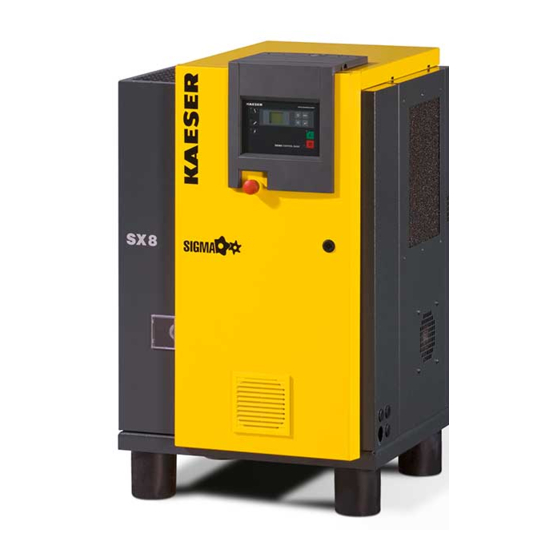
KAESER KOMPRESSOREN SX Service Manual (122 pages)
Screw Compressor
Brand:
KAESER KOMPRESSOREN
| Category:
Air Compressor
| Size: 2.75 MB
Table of Contents
Table of Contents
3
1 Regarding this Document Using the Document
11
Further Documents
11
Copyright
11
Symbols and Identification
11
Warnings
11
Other Instructions and Symbols
12
Tab. 1 the Levels of Danger and Their Meaning
12
2 Technical Specification Nameplate
13
Options
13
Weight
13
Tab. 2 Nameplate
13
Tab. 3 Options
13
Temperature
14
Ambient Conditions
14
Tab. 4 Machine Weight
14
Tab. 5 Temperature
14
Tab. 6 Ambient Conditions
14
Ventilation
15
Pressure
15
Fig. 1 Maximum Relative Humidity
15
Tab. 7 Ventilation (50Hz)
15
Tab. 8 Ventilation (60Hz)
15
Free Air Delivery
16
Cooling Oil Recommendation
16
Tab. 9 Pressure Relief Valve Activating Pressure (50 Hz)
16
Tab. 10 Pressure Relief Valve Activating Pressure (60Hz)
16
Tab. 11 FAD (50 Hz)
16
Tab. 12 FAD (60 Hz)
16
Cooling Oil Charge
17
Motors and Power
17
Drive Motor
17
Tab. 13 Cooling Oil Recommendation
17
Tab. 14 Cooling Oil Charge
17
Sound Pressure Level
18
Tab. 15 Drive Motor
18
Tab. 16 Drive Motor Rated Speed (50 Hz)
18
Tab. 17 Drive Motor Rated Speed (60Hz)
18
Tab. 18 Sound Pressure Level
18
Power Supply
19
Power Supply Specifications
19
Mains Frequency: 50 Hz
19
Tab. 19 Mains Supply 200V/3/50Hz
20
Tab. 20 Mains Supply 230V/3/50Hz
20
Tab. 21 Mains Supply 400V/3/50Hz
20
Tab. 22 Supply Conditions at 400V/3/50Hz
20
Mains Frequency: 60 Hz
21
Tab. 23 Mains Supply 230V/3/60Hz
21
Tab. 24 Mains Supply 380V/3/60Hz
21
Tab. 25 Mains Supply 440V/3/60Hz
21
Tab. 26 Mains Supply 460V/3/60Hz
21
3 Safety and Responsibility Basic Information
22
Specified Use
22
Improper Use
22
User's Responsibilities
22
Observe Statutory and Universally Accepted Regulations
22
Qualified Personnel
23
Adherence to Inspection Schedules and Accident Prevention Regulations
23
Dangers
24
Safely Dealing with Sources of Danger
24
Tab. 27 Inspection Intervals According to Ordinance on Industrial Safety and Health
24
Safe Machine Operation
26
Organisational Measures
27
Danger Areas
27
Safety Devices
27
Tab. 28 Danger Areas
27
Safety Signs
28
Fig. 2 Location of Safety Signs
28
Tab. 29 Safety Signs
28
Emergencies
29
Correct Fire Fighting
29
Remove any Cooling Oil from Your Person
29
Warranty
29
Environmental Protection
30
4 Design and Function
31
Enclosure
31
Fig. 3 Enclosure Overview
31
Function
32
Floating Relay Contacts
32
Fig. 4 Machine Layout
32
Remote LOAD-IDLE Control
33
Options
33
Machine Mountings
33
Fig. 5 Machine Mountings
33
Operating Modes and Control Modes
34
Operating Modes
34
Control Modes
34
Tab. 30 Energy-Efficient Control Modes
34
Safety Devices
35
Tab. 31 Operating Modes under MODULATING Control
35
SIGMA CONTROL BASIC Keys and Indicators
36
Fig. 6 Keys
36
Fig. 7 Indicators
36
Tab. 32 Keys
36
SIGMA CONTROL BASIC Function
37
Display Layout
37
Parameter
37
Tab. 33 Indicators
37
Tab. 34 Display
37
Messages
39
Tab. 35 Parameter
39
5 Installation and Operating Conditions
40
Safety
40
Installation Conditions
40
Determining Location and Clearances
40
Ensure Adequate Ventilation
41
Exhaust Duct Design
41
Fig. 8 Recommended Machine Placement and Dimensions [MM]
41
Operating the Machine in an Air System
42
6 Installation Safety
43
Reporting Transport Damage
43
Making the Compressed Air Connection
43
Making the Power Supply Connection
44
Fig. 9 Compressed Air Connection
44
Connecting the Remote Contact LOAD-IDLE Control
45
Options
45
Anchoring the Machine
45
Fig. 10 Connections to SIGMA CONTROL BASIC
45
7 Initial Start-Up Safety
46
Instructions to be Observed before before Every Start-Up
46
Checking Installation and Operating Conditions
47
Tab. 36 Initial Start-Up after Storage
47
Tab. 37 Installation Conditions Checklist
47
Setting the Overload Protection Cut-Out
48
Filling Cooling Oil into the Airend
48
Checking Direction of Rotation
49
Starting the Machine for the First Time
49
Fig. 11 Inlet Valve Filling Port
49
Checking the Door Interlock Switch
50
Fig. 12 Location of the Interlock Switch
50
Setting the Setpoint Pressure
51
8 Operation
52
Switching on and off
52
Switching on
52
Switching off
52
Fig. 13 Switching on and off
52
Switching off in an Emergency and Switching on Again
53
Fig. 14 Switching off in an Emergency
53
Tab. 38 Switching off With/Without Run-On Time
53
Acknowledging Alarm and Warning Messages
54
Setting Parameters
54
Fig. 15 Acknowledging Messages
54
9 Fault Recognition and Rectification
56
Basic Information
56
Alarm Messages (Machine Stop)
56
Warning Messages
57
Tab. 39 Alarm Indications
57
Tab. 40 Warning Messages
57
Other Faults
58
Tab. 41 Other Faults and Actions
58
10 1 Maintenance
59
Safety
59
Maintenance Schedule
60
Logging Maintenance Work
60
Resetting Maintenance Interval Counters
60
Regular Maintenance Tasks
60
Tab. 42 Regular Maintenance Tasks
60
Cooling Oil: Change Interval
61
Regular Service Tasks
62
Cooler: Cleaning or Renewing the Filter Mats
62
Tab. 43 Cooling Oil Changing Intervals
62
Tab. 44 Regular Service Tasks
62
Cleaning or Replacing the Control Cabinet Filter Mats
63
Fig. 16 Filter Mat for the Air and Oil Cooler
63
Cooler Maintenance
64
Fig. 17 Control Cabinet Ventilation Grill
64
Air Filter Maintenance
65
Fig. 18 Filter Mat for the Air and Oil Cooler
65
Drive Motor Maintenance
66
Maintaining the Drive Belts
66
Fig. 19 Air Filter Maintenance
66
Checking the Cooling Oil Level
67
Fig. 20 Changing the Belt
67
Tab. 45 Permissible Cooling Oil Level under LOAD
67
Pressure Relief Valve Checking
68
Fig. 21 Checking the Cooling Oil Level
68
Checking the Excess Temperature Safety Shutdown Function
69
Venting the Machine (Depressurizing)
69
Fig. 22 Venting the Machine
70
Topping up the Cooling Oil
71
Venting the Machine (Depressurizing)
72
Fig. 23 Topping up the Cooling Oil
72
Topping up with Cooling Oil and Trial Run
73
Changing the Cooling Oil
74
Fig. 24 Changing the Cooling Oil, Oil Separator Tank
74
Fig. 25 Changing the Cooling Oil, Oil Cooler
75
Changing the Oil Filter
76
Changing the Oil Separator Cartridge
77
Fig. 26 Changing the Oil Filter
77
Fig. 27 Changing the Oil Separator Cartridge
78
Document Maintenance and Service Work
79
Tab. 46 Logged Maintenance Tasks
79
11 Spares, Operating Materials, Service
80
Note the Nameplate
80
Ordering Consumable Parts and Operating Materials
80
Kaeser Air Service
80
Tab. 47 Consumable Parts
80
Service Addresses
81
Spare Parts for Service and Repair
81
12 Decommissioning, Storage and Transport
84
Putting out of Operation
84
Packing
84
Storage
84
Transporting
85
Safety
85
Transporting with a Forklift Truck
85
Transporting with a Crane
85
Fig. 28 Transporting with a Forklift Truck
85
Disposal
86
Fig. 29 Transporting with a Crane
86
13 Annex
87
Pipeline and Instrument Flow Diagram (P+I Diagram)
87
Pipe and Instrument Flow Diagram (P&I Diagram): MODULATING Control Mode
93
Dimensional Drawing
99
Electrical Diagram
102
Advertisement
Advertisement
Related Products
KAESER KOMPRESSOREN SIGMA CONTROL BASIC
KAESER KOMPRESSOREN CSD 102
KAESER KOMPRESSOREN CSD 122
KAESER KOMPRESSOREN CSD 82
KAESER KOMPRESSOREN EPC 1000-2-G
KAESER KOMPRESSOREN EPC 150-2-G
KAESER KOMPRESSOREN EPC 230-2-G
KAESER KOMPRESSOREN EPC 420-2-G
KAESER KOMPRESSOREN EPC 550-2-G
KAESER KOMPRESSOREN EPC 750-2-G
KAESER KOMPRESSOREN Categories
Air Compressor
Controller
Blower
Water Filtration Systems
Dryer
More KAESER KOMPRESSOREN Manuals
Login
Sign In
OR
Sign in with Facebook
Sign in with Google
Upload manual
Upload from disk
Upload from URL