Sign In
Upload
Manuals
Brands
Kübler Manuals
Measuring Instruments
SMC2.4
Kübler SMC2.4 Manuals
Manuals and User Guides for Kübler SMC2.4. We have
1
Kübler SMC2.4 manual available for free PDF download: Safety Manual
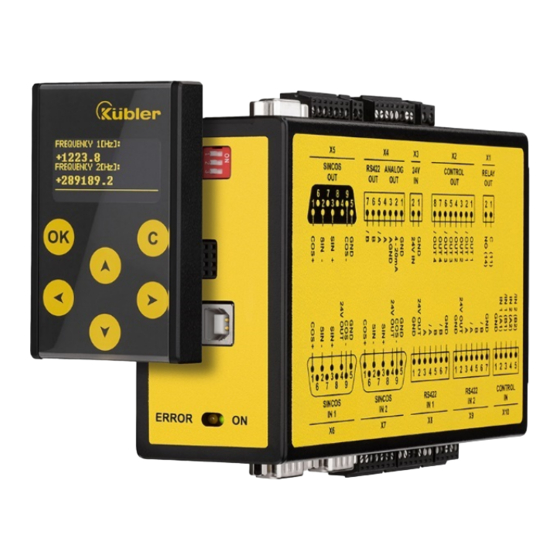
Kübler SMC2.4 Safety Manual (235 pages)
Safety Motion Monitors for Incremental Encoders / Sensors
Brand:
Kübler
| Category:
Measuring Instruments
| Size: 11 MB
Table of Contents
Deutsch
3
Table of Contents
3
1 Sicherheit und Verantwortung
6
Allgemeine Sicherheitshinweise
6
Bestimmungsgemäße Verwendung
6
Installation
7
Reinigungs-, Pflege- und Wartungshinweise
7
2 Allgemeines
9
3 Verfügbare Ausführungen
10
4 Blockschaltbilder und Anschlüsse
11
SMC2.4 Blockschaltbild
11
SMC2.4 Anschlüsse
11
SMC1.3 Blockschaltbild
12
SMC1.3 Anschlüsse
12
5 Beschreibung der Anschlüsse
13
Spannungsversorgung
14
Geberversorgung
15
Direkter Anschluss der Geberversorgung
16
Indirekter Anschluss der Geberversorgung
16
Gebereingänge
18
Steuereingänge
19
Steuereingänge CONTROL in 1
19
Steuereingänge CONTROL in 2
21
Geberausgang
22
Analogausgang 4 bis 20 Ma
23
Steuerausgänge
24
Relaisausgänge
25
DIL-Schalter
26
Schnittstelle Anzeigegerät SMCB
27
USB Schnittstelle für PC Kommunikation
27
LED Statusanzeige
28
6 Betriebsarten SMC2.4
29
Kombination: RS422 + RS422
30
Kombination: RS422 + HTL (Differenziell)
31
Kombination: RS422 + HTL (A, B, 90°)
32
Kombination: RS422 + HTL (A)
33
Kombination: HTL (Differenziell) + HTL (Differenziell)
34
Kombination: HTL (Differenziell) + HTL (A, B, 90°)
35
Kombination: HTL (Differentiell) + HTL (A)
36
Kombination: HTL (A, B, 90°) + HTL (A, B, 90°)
37
Kombination: HTL (A, B, 90°) + HTL (A)
38
Kombination: HTL (A) + HTL (A)
39
7 Betriebsarten SMC1.3
40
Kombination: RS422 SIL2 / Pld Geber
41
Kombination: HTL (Differentiell) SIL2 / Pld Geber
42
8 Inbetriebnahme
43
Installation IM Schaltschrank
43
Montage / Demontage
44
Vorbereitung zur Parametrierung und Test
45
Parametrierung mit PC
46
Visualisierung mit SMCB
47
9 Parametrierung
48
Betriebsart
48
Drehrichtung
48
Frequenzverhältnis
50
Fehler Löschen
52
Sampling Time und Filter
53
Wait Time
53
F1-F2 Selection
54
Divergence Parameter
54
Frequenzvergleich
55
Positionsvergleich
55
Power-Up Delay
55
Encoder-Splitterausgang
56
Analogausgang
56
Steuerausgänge Einstellen
57
Relaisausgänge Einstellen
57
Steuereingänge Einstellen
57
Fehler Simulation
58
10 Abschluss Inbetriebnahme
59
11 Fehlererkennung
60
Fehlerdarstellung
60
Initialization Test
61
Runtime Test
62
Fehler Zurücksetzen
63
Fehlererkennungszeit
64
12 Überwachungsfunktionen
65
Überdrehzahl (Switch Mode = 0)
65
Unterdrehzahl (Switch Mode = 1)
66
Frequenzband (Switch Mode = 2)
67
Stillstand (Switch Mode = 3)
68
Überdrehzahl (Switch Mode = 4)
69
Unterdrehzahl (Switch Mode = 5)
70
Frequenzband (Switch Mode = 6)
71
Frequenz > 0 Hz (Switch Mode = 7)
72
Frequenz < 0 Hz (Switch Mode = 8)
73
Takterzeugung für Gepulste Rücklesung (Switch Mode = 9)
74
STO/SBC/SS1 durch Eingang (Switch Mode = 10)
75
STO/SBC durch Zustand (Switch Mode = 10)
76
SS1 durch Eingang (Switch Mode = 10)
76
SLS (Überdrehzahl) durch Eingang (Switch Mode = 11)
78
SMS (Switch Mode = 12)
79
SDI (F > 0 Hz) durch Eingang (Switch Mode = 13)
80
SDI (F < 0 Hz) durch Eingng (Switch Mode = 14)
81
SSM (Unterdrehzahl) durch Eingang (Switch Mode = 15)
82
SSM (Frequenzband) durch Eingang (Switch Mode = 16)
83
SOS/SLI/SS2 durch Eingang (Switch Mode = 17)
84
Stillstand durch Eingang (Switch Mode = 18)
85
SSM (Frequenzband) durch Eingang (Switch Mode = 19)
87
Kein Stillstand (Switch Mode = 20)
88
Rampenüberwachung (Switch Mode = 21)
88
Rampenüberwachung (Switch Mode = 22)
90
13 Reaktionszeiten
92
Reaktionszeit des Relaisausgangs
92
Reaktionszeit des Analogausgangs
92
Reaktionszeit der Digitalausgänge
93
Reaktionszeit des Splitterausgangs
93
Reaktionszeit bei Frequenzfehlerauswertung
94
14 Anschluss der Eingänge
96
Anschluss: 1-Polig nicht Getakteter Eingang
96
Anschluss: 1-Polig Getakteter Eingang
97
Anschluss: 2-Polig nicht Getakteter Eingang
98
Anschluss: Schaltpunktumschaltung
99
15 Anschluss der Ausgänge
100
16 EDM-Funktion
100
EDM: 1 Externes Relais an X4 mit SIL1
101
EDM: 1 Externes Relais an X4 mit SIL1
102
EDM: 2 Externe Relais an X4 mit SIL2
103
EDM: 2 Externe Relais an X4 mit SIL2
104
EDM: 2 Externe Relais an X4 mit SIL3
105
EDM: 2 Externe Relais an X4 mit SIL3
106
EDM: 2 Externe Relais an X4 mit SIL3
107
EDM: 1 Externes Relais an X1/2 mit SIL1
108
EDM: 2 Externe Relais an X1/2 mit SIL2
109
EDM: 2 Externe Relais an X1/2 mit SIL3
110
17 Overlap
112
18 Kaskadierung
113
19 Technische Daten
114
Abmessungen
116
20 Zertifikat
117
English
123
1 Safety Instructions and Responsibility
126
General Safety Instructions
126
Use According to the Intended Purpose
126
Installation
127
Cleaning, Maintenance and Service Notes
127
2 Introduction
128
3 Available Models
129
4 Block Diagrams and Connections
130
SMC2.4 Block Diagram
130
SMC2.4 Connections
130
SMC1.3 Block Diagram
131
SMC1.3 Connections
131
5 Description of Connections
132
Power Supply
133
Encoder Supply
134
Direct Encoder Supply
135
Indirect Encoder Supply
135
Encoder Inputs
137
Control Inputs
138
Control Outputs CONTROL in 1
138
Control Outputs CONTROL in 2
140
Encoder Output
141
Analog Output 4 to 20 Ma
142
Control Output
143
Relais Outputs
144
DIL Switch
145
SMCB Operator Interface
146
USB Interface for the OS6.0 Operator Surface
146
Leds / Status Indication
147
6 Operational Modes SCM2.4
148
Combination: RS422 + RS422
149
Combination: RS422 + HTL (Differential)
150
Combination: RS422 + HTL (A, B, 90°)
151
Combination: RS422 + HTL (A)
152
Combination: HTL (Differential) + HTL (Differential)
153
Combination: HTL (Differntial) + HTL (A, B, 90°)
154
Combination: HTL (Differential) + HTL (A)
155
Combination: HTL (A, B, 90°) + HTL (A, B, 90°)
156
Combination: HTL (A, B, 90°) + HTL (A)
157
Combination: HTL (A) + HTL (A)
158
7 Operation Modes SMC1.3
159
Combination: RS422 SIL2 / Pld Encoder
160
Combination: HTL (Differential) SIL2 / Pld Encoder
161
8 Commissioning
162
Cabinet Installation
162
Mounting / Dismounting
163
Preparations for Setup and Testing
164
Parameter Setting by PC
165
Visualization by the SMCB Operator Unit
166
9 Setup
167
Operational Mode Settings
167
Direction Settings
167
Frequency Ratio Settings
169
Clear Errors
170
Sampling Time and Fliter
171
Wait Time
172
F1-F2 Selection
172
Divergence Parameters
173
Frequency Comparison
173
Sensor Position Comparison
174
Power-Up Delay
174
Encoder Splitter Output
175
Analog Output
175
Control Output Settings
176
Relay Output Settings
176
Control Input Settings
176
Producing an Error
177
10 Completion of the Setup Procedure
178
11 Error Detection
179
Error Representation
179
Initialization Test
180
Runtime Test
181
Error Clearing
182
Error Detection Time
183
12 Monitoring Functions
184
Overspeed (Switch Mode = 0)
184
Underspeed (Switch Mode = 1)
185
Frequency Band (Switch Mode = 2)
186
Standstill (Switch Mode = 3)
187
Overspeed (Switch Mode = 4)
188
Underspeed (Switch Mode = 5)
189
Frequency Band (Switch Mode = 6)
190
Frequency > 0 Hz (Switch Mode = 7)
191
Frequency < 0 Hz (Switch Mode = 8)
192
Clock Generation for Pulsed Readback (Switch Mode = 9)
193
STO/SBC Produced by Situation (Switch Mode = 10)
195
SLS Produced by Input (Switch Mode = 11)
196
SMS (Switch Mode = 12)
197
SDI Produced by Input (F > 0 Hz), (Switch Mode = 13)
198
SDI Produced by Input (F < 0 Hz) (Switch Mode = 14)
199
SSM Via Input (Switch Mode = 15)
200
SSM Via Input (Switch Mode = 16)
201
SOS/SLI/SS2 Via Input (Switch Mode = 17)
202
Standstill Via Input (Switch Mode = 18)
203
SMS (Frequency Band) Via Input (Switch Mode = 19)
204
No Standstill (Switch Mode = 20)
205
Ramp Monitoring (Switch Mode = 21)
205
Ramp Monitoring (Switch Mode = 22)
207
13 Response Times
209
Response Time of the Relay Output
209
Response Time of the Analog Output
209
Response Time of the Digital Outputs
210
Response Time of the Splitter Output
210
Response Time of the Frequency Error Evaluation
211
14 Connection of the Inputs
213
Connection: Unipolar, Un-Clocked Inputs
213
Connection: Unipolar, Clocked Inputs
214
Connection: Bipolar, Un-Clocked Inputs
215
Connection: Switching Point Switchover
216
15 Connection of the Outputs
217
16 EDM Function
217
EDM: 1 External Relay on X4 with SIL1
218
EDM: External Relay at X4 with SIL1
219
EDM: 2 External Relays at X4 with SIL2
220
EDM: 2 External Relays at X4 with SIL2
221
EDM: 2 External Relays at X4 with SIL3
222
EDM: 2 External Relays at X4 with SIL3
223
EDM: 2 External Relays at X4 with SIL3
224
EDM: 1 External Relay at X1/2 with SIL1
225
EDM: 2 External Relays at X1/2 with SIL2
226
EDM: 2 External Relays at X1/2 with SIL3
227
17 Overlap
229
18 Cascading
230
19 Technical Specifications
231
Dimensions
233
20 Certificate
234
Advertisement
Advertisement
Related Products
Kübler SMC1.3
Kübler SAEJ1939
Kübler SMCB.1
Kübler SMCB-Display
Kübler Sendix SIL Series
Kübler Sendix SIL 7053FS2
Kübler Sendix SIL 7063FS2
Kübler Sendix SIL 5853FS3
Kübler Sendix M58 Series
Kübler Sendix S3684
Kübler Categories
Media Converter
Cash Counter
Measuring Instruments
Monitor
Controller
More Kübler Manuals
Login
Sign In
OR
Sign in with Facebook
Sign in with Google
Upload manual
Upload from disk
Upload from URL