Sign In
Upload
Manuals
Brands
JYTEK Manuals
Control Unit
USB-61210
JYTEK USB-61210 Manuals
Manuals and User Guides for JYTEK USB-61210. We have
1
JYTEK USB-61210 manual available for free PDF download: User Manual
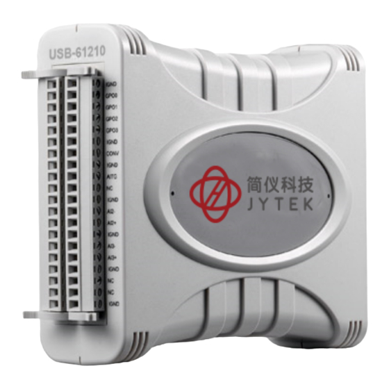
JYTEK USB-61210 User Manual (56 pages)
4-CH 16-Bit 2MS/s Simultaneous-Sampling USB DAQ Module
Brand:
JYTEK
| Category:
Control Unit
| Size: 4 MB
Table of Contents
Table of Contents
5
List of Figures
7
1 Introduction
11
Overview
11
Features
11
Applications
11
Specifications
11
General Specifications
12
Analog Input
13
Schematics
14
Module
14
Figure 1-1: USB-61210 Module Rear View
14
Figure 1-2: USB-61210 Module Side View
15
Figure 1-3: USB-61210 Module Front View
16
Module Stand
17
Figure 1-4: Module, Stand, Connector, and USB Cable
17
Figure 1-5: Module, Stand, & Wall Mount Kit Side View (W/ Connections)
18
Figure 1-6: Module in Stand Front View
18
Figure 1-7: Module Stand Top View
19
Figure 1-8: Module Stand Side Cutaway View
20
Figure 1-9: Module Stand Front View
20
Connector Pin Assignment
21
Connector Signal Description
21
Table 1-1: USB-61210 Pin Assignment
21
Analog Input Signal Connection
22
Table 1-2: CN1/CN2 I/O Signal Description
22
Figure 1-10: GRND-Referenced Source W/ DIFF Input
23
Figure 1-11: Floating Source W/ DIFF Input
23
Software Support
24
Driver Support for Windows
24
1.10 Utilities for Windows
24
2 Getting Started
25
Unpacking Checklist
25
Attaching the Module Stand
25
Rail Mounting
26
Figure 2-1: Rail Mount Kit
26
Figure 2-2: Module Pre-Rail Mounting
26
Wall Mounting
27
Figure 2-3: Module Rail-Mounted
27
Figure 2-4: Wall Mount Holes
27
Installing the USB-61210 Module
28
Connecting the USB-61210 Module
28
Figure 2-5: Module with Wall Mount Apparatus
28
Device ID
29
Figure 2-6: USB-61210 Module in Windows Device Manager
29
Hardware Configuration
30
Figure 2-7: Device ID Selection Control
30
3 Operation & Calibration
31
Operation
31
Signal Function
31
Figure 3-1: Carrier Board Functional Block Diagram
31
A/D Conversion
32
Figure 3-2: Daughter Board Functional Block Diagram
32
Table 3-1: Bipolar Analog Input Range and Output Digital Code
33
Trigger Sources
35
Figure 3-4: Configuring Different Sampling Rates
35
Figure 3-5: Below-Low Analog Triggering
36
Figure 3-6: Above-High Analog Triggering
36
Trigger Modes
37
Figure 3-7: Digital Triggering
37
Figure 3-8: Post Trigger Without Retriggering
37
Figure 3-9: Delayed Trigger
38
Figure 3-10: Middle Trigger
38
Figure 3-11: Pre-Trigger
39
Figure 3-12: Post Trigger with Retriggering
39
Programmable Function I/O
40
Figure 3-13: Gated Trigger
40
Table 3-2: Pin Definition of LVTTL Digital I/O
41
Basic Timer/Counter Function
42
General Purpose Timer/Counter Modes
42
Table 3-3: Timer/Counter Pin Definition
42
Figure 3-14: Mode 1-Simple Gated-Event Calculation
43
Figure 3-15: Mode 2-Single Period Measurement
43
Figure 3-16: Mode 3-Single Pulse-Width Measurement
44
Figure 3-17: Mode 4-Single-Gated Pulse
44
Figure 3-18: Mode 5-Single-Triggered Pulse
45
Figure 3-19: Mode 6-Re-Triggered Single Pulse
45
Figure 3-20: Mode 7-Single-Triggered Continuous Pulse
46
Figure 3-21: Mode 8-Continuous Gated Pulse
46
Figure 3-22: Mode 9-Edge Separation Measurement
47
Figure 3-23: Mode 10-PWM Output Following Trigger
47
Figure 3-24: Mode 10-PWM Output Following GATE Control
47
Isolation
48
Calibration
48
Figure 3-25: Isolation
48
Auto-Calibration
49
Loading Calibration Constants
49
Saving Calibration Constants
49
Important Safety Instructions
51
Warranty Policy
53
Getting Service
55
Advertisement
Advertisement
Related Products
JYTEK USB-61900 Series
JYTEK USB-61901
JYTEK USB-61902
JYTEK USB-61903
JYTEK USB-67230
JYTEK USB-67250
JYTEK USB-5321
JYTEK USB-5322
JYTEK USB-5323
JYTEK USB-5324
JYTEK Categories
Computer Hardware
Control Unit
Controller
Measuring Instruments
Chassis
More JYTEK Manuals
Login
Sign In
OR
Sign in with Facebook
Sign in with Google
Upload manual
Upload from disk
Upload from URL