Sign In
Upload
Manuals
Brands
JYTEK Manuals
Control Unit
PXIe-69529
JYTEK PXIe-69529 Manuals
Manuals and User Guides for JYTEK PXIe-69529. We have
1
JYTEK PXIe-69529 manual available for free PDF download: User Manual
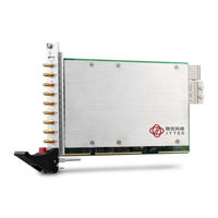
JYTEK PXIe-69529 User Manual (28 pages)
8-CH 24-Bit 204.8 kS/s Dynamic Signal Acquisition Module
Brand:
JYTEK
| Category:
Control Unit
| Size: 1 MB
Table of Contents
Getting Service
2
Table of Contents
3
Introduction
7
1�1 Features
7
Applications
7
Specifications
8
1�3�1 Analog Input
8
Table 1-1: Channel Characteristics
8
Figure 1-1: Analog Input Channel Bandwidth, ±0.2 Vpp
9
Figure 1-2: Analog Input Channel Bandwidth, ±2 Vpp
9
1�3�2 Timebase
10
1�3�3 Triggers
10
General Specifications
10
Table 1-2: Timebase
10
Table 1-3: Trigger Source & Mode
10
Table 1-4: Digital Trigger Input
10
Software Support
11
1�4�1 Sdk
11
1�4�2 Dsa-Dask
11
1�5 Device Layout and I/O Array
12
Figure 1-3: Pxie-69529 Schematic
12
Figure 1-4: Pxie-69529 I/O Array
13
Getting Started
14
Installation Environment
14
2�2 Installing the Module
15
Operations
16
Functional Block Diagram
16
3�2 Analog Input Channel
16
Analog Input Front-End Configuration
16
Figure 3-1: Analog Input Architecture
16
3�2�2 Input Range and Data Format
17
Table 3-1: Input Range and Data Format
17
3�2�3 ADC and Analog Input Filter
18
3�2�4 DMA Data Transfer
18
Table 3-2: Input Range Midscale Values
18
Table 3-3: ADC Sample Rates Vs DDS Output Clock
18
Figure 3-2: Linked List of PCI Address DMA Descriptors
19
3�3 Trigger Source and Trigger Modes
20
Figure 3-3: Trigger Architecture
20
Figure 3-4: External Digital Trigger
20
3�4 Trigger Mode
22
Table 3-4: Preferred Characteristics for Analog Triggers
22
Figure 3-5: Analog Trigger Conditions
22
Figure 3-6: Post-Trigger Acquisition
23
Figure 3-7: Delay Trigger Mode Acquisition
23
3�5 ADC Timing Control
24
3�5�1 Timebase
24
3�5�2 DDS Timing Vs� ADC
24
Table 3-5: Timing Relationship between ADC and PLL Clock
24
Figure 3-8: Re-Trigger Mode Acquisition
24
Figure 3-9: Timebase Architecture
24
3�5�3 Filter Delay in ADC
25
Synchronizing Multiple Modules
25
Table 3-6: ADC Filter Delay
25
Table 3-7: SSI Timing Signal Definitions
25
3�6�2 Ssi_Sync_Start
26
3�6�3 Ssi_Trig
26
Figure 3-10: SSI Architecture
26
Ssi_Timebase
26
Appendix A Calibration
27
Calibration Constant
27
Auto-Calibration
27
Important Safety Instructions
28
Advertisement
Advertisement
Related Products
JYTEK PXIe-5321
JYTEK PXIe-5322
JYTEK PXIe-5323
JYTEK PXIe-5324
JYTEK PXI-93518
JYTEK PXI-67921
JYTEK PXI-67931
JYTEK PCIe-5321
JYTEK PCIe-5322
JYTEK PCIe-5323
JYTEK Categories
Computer Hardware
Control Unit
Controller
Measuring Instruments
Chassis
More JYTEK Manuals
Login
Sign In
OR
Sign in with Facebook
Sign in with Google
Upload manual
Upload from disk
Upload from URL