Sign In
Upload
Manuals
Brands
JRC Manuals
Compass
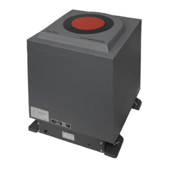
ALPHAMIDICOURSE Mk2
JRC ALPHAMIDICOURSE Mk2 Manuals
Manuals and User Guides for JRC ALPHAMIDICOURSE Mk2. We have
1
JRC ALPHAMIDICOURSE Mk2 manual available for free PDF download: Installation And Operation Manual
JRC ALPHAMIDICOURSE Mk2 Installation And Operation Manual (99 pages)
Gyrocompass
Brand:
JRC
| Category:
Compass
| Size: 7 MB
Table of Contents
Table of Contents
2
I Preface
5
Revision History
5
Points of Attention
5
Glossary
6
Storage
6
Caution
7
II.1 Warning Label
7
II.2 Location Warning Label
7
II.3 Cautions
7
Introduction
12
III.1 Display and Alarm
12
III.2 Types of Alarm Functions
12
III.3 Step Signal Type Repeater Signal Output Function
13
III.4 Serial Signal Type Repeater Signal Output Function
13
III.5 Automatic Speed Error Correction Function
13
III.6 Rate of Turn Signal Output Function
14
III.7 Timer Start
14
III.8 Function of the External Heading Sensor
14
III.9 Pendulum Function
14
III.10 Warranty Conditions
15
III.11 Ordering of Additional Items
15
Installation Instructions
16
Installation Guidelines
16
General and Specific Tools
16
Unpacking of the Alphamidicourse Mk2
17
Mounting of Master Compass
18
Fitting Master Compass
19
Remove Parts from Master Compass Mounting Ring
20
Remove Packing Material from Shock Absorbers
20
Unpacking of Sensitive Element
21
Mounting of Sensitive Element
22
Filling with Damping Oil
23
Attach Connector to Sensitive Element
23
Name and Function of each Unit
24
Configuration
24
Connecting the Alphamidicourse Mk2
25
DIP Switch Settings
28
Dip Switch Settings Master Compass
28
Dip Switch Settings Control Box Part 1
29
Dip Switch Settings Control Box Part 2
30
Dip Switch Settings GPANEL-A Board
31
Jumper Settings
32
First Start-Up Procedure
33
Start-Up Master Compass
33
Configuring the Gyro Sphere
34
Setting the Latitude Input Source
34
Setting the Speed Input Source
35
Balancing the Horizontal Ring
35
Adjusting True Heading
36
Advanced Settings
37
Extension Menu Overview
38
Operation
43
Operating Panel
43
Explanation of the Operating Panel
44
Data Indications
46
And S.S.E
47
And Gyt
47
Latitude
48
Ship Speed
49
Rate of Turn
49
Error
50
Start and Stop Sequence
51
Start and Running
52
Start
52
Set Timer Starting Time
53
Set Start Heading
54
Confirming Latitude Input
54
Synchronization of the Repeater Compass
55
Settling Time
56
Confirming Ship Speed Input
56
Set Rate of Turn Filter Constant
57
Heading Sensor Selection
57
Pendulum Function
58
Monitoring While Running
58
Confirmation of Alarm Status
59
Confirmation of Gyro Compass True Heading
59
Confirmation of Latitude
59
Confirmation of Ship Speed
59
Alarm
60
Alarm List
61
Alarm List of Alert Management System (AMS)
62
Alert Priority (※4)
63
Alert Categories (※5)
63
Turning the Gyro Compass off
64
Specifications
65
Input Signal Specifications
66
Output Signal Specifications
67
Maintenance
68
General Procedures
68
Periodical Checks
69
Warning Label Check
69
Spare Parts
69
Disposal Method
69
Replacement of Sensitive Element S/E
70
Troubleshooting
71
General
71
Before Troubleshooting
71
Corrective Measures
72
Corrective Measures When an Alarm Is Activated
72
Failure Phenomena and Corrective Measures
72
Alarm Code 1: Power Supply Failure
72
Alarm Code 2: Power Supply Abnormal
73
Alarm Code 3: Inverter Failure
73
Alarm Code 6: Rotor Level Failure
73
Alarm Code 8: Zero Cross Failure
73
Alarm Code A: System Communication Failure (1)
74
Alarm Code B: System Communication Failure (2)
74
Alarm Code C or D: GPS Communication Stop or Failure of GPS Data
74
Alarm Code E or F: System Internal Communication Failure (1) or System Internal Communication Failure (2)
75
Alarm Code G: Master Compass Heading Failure
75
Alarm Code L or N: External Heading Sensor Communication Stop or External Heading Sensor Data Failure
75
Alarm Code P or U: LOG (Serial Signal) Communication Stop or LOG (Serial Signal) Data Failure
75
Alarm Code U: LOG Contact Failure
75
Alarm Code R: E5V Failure
76
Gyro Compass Does Not Function, When Power Switch Turned on
76
Alarm 3 and a Are Activated at the same Time When Powering on
76
Each Repeater Does Not Operate
76
Others
76
Fuse Replacement
77
Master Compass Inverter Fuse
78
Appendices
79
Drawings
79
Dimensions of Control Unit
80
Dimensions of Master Compass
81
Master Compass Without Housing
82
ICNT Board of Control Unit
83
Connection Diagram
84
Cable Diagram
85
Installation Drawing
86
Check Sheet [Maintenance] Alphamidicourse Mk2
87
Periodical Check Tables
93
Periodical Table (Once a Day)
93
Periodical Table (Once a (Halve) Year)
94
Return Slip Sensitive Element
95
Installation Drawing of Alphaheading
97
Advertisement
Advertisement
Related Products
JRC MA-7110-6XAH
JRC MA-7110-6XA
JRC ALPHATRON AlphaPilot MFM APH-5
JRC ALPHATRON AlphaPilot MFM APH-7
JRC Alpatron AlphaMidiCourse
JRC Categories
Marine Radar
Water Filtration Systems
Marine Equipment
Receiver
Radio Parts
More JRC Manuals
Login
Sign In
OR
Sign in with Facebook
Sign in with Google
Upload manual
Upload from disk
Upload from URL