Sign In
Upload
Manuals
Brands
Johnson Controls Manuals
Air Conditioner
SERIES 40
Johnson Controls SERIES 40 Manuals
Manuals and User Guides for Johnson Controls SERIES 40. We have
1
Johnson Controls SERIES 40 manual available for free PDF download: Installation Operation & Maintenance
Johnson Controls SERIES 40 Installation Operation & Maintenance (251 pages)
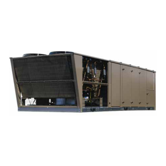
ROOFTOP 25, 30 AND 40 TON WITH IPU CONTROL
Brand:
Johnson Controls
| Category:
Air Conditioner
| Size: 13 MB
Table of Contents
Table of Contents
5
Section 1 - Introduction
17
Ecological and Economical Design
17
Cooling and Heating
17
Indoor Air Quality (IAQ)
17
High-Efficiency Motors
17
Condensing Section
17
Figure 1 - Packaged Rooftop Air Conditioning Unit
17
Heating Section
18
Air Management
18
Controls
19
Rooftop Controller
19
Bacnet
19
General
19
Safety Considerations
19
Notes, Cautions and Warnings
19
Gas Fired Models
19
What to Do if You Smell Gas
19
All Models
20
Inspection
20
Figure 2 - Component Location
21
Section 2 - Installation
23
Approvals
23
Limitations
23
Table 1 - Cooling and Electrical Application
23
Table 2 - Cooling and Electrical Application Limitations
23
Talbe 3 - Standard Gas Heating Capacities
24
Table 4 - Temperature Rise
24
Table 5 - Minimum Heating Cfm
24
Figure 3 - Unit Clearances
25
Locations and Clearances
25
Rigging and Handling
26
Service Access
26
Table 6 - Unit Cornerweight
26
Figure 4 - Typical Rigging
27
Table 7 - Unit Center of Gravity
27
Table 8 - Unit Weights
27
Figure 5 - Center of Gravity
28
Table 10 - Exhaust Fan Motor Vfd Weights
28
Table 9 - Supply Fan Motor Vfd Weights
28
Table 11 - General Physical Data
29
Figure 6 - Bottom Supply and Return
31
Figure 7- End Return, Bottom Supply
32
Figure 8 - Bottom Return, Front & Rear Supply
33
Figure 9 - End Return, Front & Rear Supply
34
Figure 10 - Partial Roof Curb Model 1Rc0455P
35
Figure 11 - Field Installed Disconnect
36
Figure 12 - 25 Ton Overhead View
36
Figure 13 - 30 and 40 Ton Overhead View
37
Figure 14 - 25 Ton Major Component Layout
37
Figure 15 - 30 and 40 Ton Major Component Layout
37
Figure 16 - Cabinet Door Configuration
38
Cfm, Static Pressure, and Power - Altitude and Temperature Corrections
39
Table 12 - Refrigerant Factory Charge R-410A
39
Table 13 - Altitude Correction Factors
39
Figure 17 - Altitude/Temperature Conversion Factor
40
Figure 18 - 40 Ton Forward Curve Example
41
Table 14 - Fan Performance - 25 Ton
42
Figure 19 - Fan Performance - 25 Ton Forward Curve
44
Table 15 - Fan Performance - 30 Ton
45
Figure 20 - Fan Performance - 30 Ton Forward Curve
47
Table 16 - Fan Performance - 40 Ton
48
Figure 21 - Fan Performance - 40 Ton Forward Curve
50
Table 17 - Component Static Resistance
51
Table 18 - Supply Fan Motor and Drive Data
52
Table 19 - Exhaust Fan Drive Data
52
Table 20 - Power Exhaust - One Forward Curved Fan 25 Ton
53
Figure 22 - Power Exhaust - One Forward Curve Fan - 25 Ton
54
Table 21 - Power Exhaust - Two Forward Curved Fans - 30 & 40 Ton
55
Figure 23 - Power Exhaust - Two Forward Curved Fans - 30 & 40 Tons
56
Electrical Data
57
Table 22 Electrical Data 25 Ton 208/230 Volt Without Erv
57
Table 23 Electrical Data 25 Ton 230 Volt with Erv
59
Table 24 Electrical Data 25 Ton 460 Volt Without Erv
60
Table 25 Electrical Data 25 Ton 460 Volt with Erv
61
Table 26 Electrical Data 25 Ton 575 Volt Without Erv
62
Table 27 Electrical Data 25 Ton 575 Volt with Erv
63
Table 28 Electrical Data 30 Ton 208/230 Volt Without Erv
64
Table 29 Electrical Data 30 Ton 208/230 Volt with Erv
66
Table 30 Electrical Data 30 Ton 460 Volt Without Erv
68
Table 31 Electrical Data 30 Ton 460 Volt with Erv
69
Table 32 Electrical Data 30 Ton 575 Volt Without Erv
70
Table 33 Electrical Data 30 Ton 575 Volt with Erv
71
Table 34 Electrical Data 40 Ton 208/230 Volt Without Erv
72
Table 35 Electrical Data 40 Ton 230 Volt with Erv
74
Table 36 Electrical Data 40 Ton 460 Volt Without Erv
75
Table 37 Electrical Data 40 Ton 460 Volt with Erv
76
Table 38 Electrical Data 40 Ton 575 Volt Without Erv
77
Table 39 Electrical Data 40 Ton 575 Volt with Erv
78
Air Hoods
79
Air Hoods for Fixed Outside Air
79
Air Hoods for Economizer
79
Figure 25 - Reccommended Drain Piping
79
Figure 24 - Drain Trap Showing Water Location During Draw through Operation Stages
79
Air Hoods for Exhaust Air
80
Compressors
79
Condensate Drain
79
Condensate Drain Piping
79
Condensate Drain Trap
79
Filters
79
Field Wiring
80
Thermostat
80
Space Sensor
80
CO Sensor
80
Occupied/Unoccupied Input
80
Shutdown Input
80
Smoke Purge Input
80
VAV Heat Relay Output
81
Bacnet Communication
81
Return Air Bypass Damper
81
CTB3 Field Control Wiring (Inputs)
82
Figure 26 - Field Control Wiring - Inputs
82
General
83
Power and Control Wiring
83
Power Wiring Detail
83
Transducer Pneumatic Tubing
84
Static Pressure Control Plastic Tubing
84
Duct Static Transducer
84
Building Pressure Transducer
84
Static Pressure Probe Installation
84
Figure 27 - Static Pressure Probe Installation
84
Duct System
85
Duct Connection Guidelines
85
Roof Curb Installation
85
General Information
85
Sound and Vibration Transmission
85
Gas Heating
86
Gas Piping
86
Gas Connection
86
Table 40 - Pipe Sizes
86
Figure 28 - Typical Gas Piping Connection
86
Vent and Combustion Air
87
Electric Heat
87
Hot Water Heat
87
Figure 29 - Vent and Combustion Air Hoods
87
Piping Connections
88
Steam Heat
89
Figure 30 - Steam Piping Cross-Section
89
Figure 31 - Hot Water Piping Cross-Section
90
Piping Connections
90
Section 3 - Start-Up
91
Crankcase Heaters
91
Checking the System Prior to Initial Start (no Power)
91
Unit Checks
91
Unit Checks - Power Applied
92
Verifying Compressor Rotation
92
Compressor Oil Level Check
92
Air Balance
93
Checking Supply Air CFM
93
Supply Air Drive Adjustment
93
Table 41 - Blower Speed Rate of Change
94
Drive Adjustment Tables
95
Table 42 - 25 Ton Drive Adjustment for Constant Volume & Vav Units Class
95
Table 43 - 30 Ton Drive Adjustment for Constant Volume & Vav Units Class
95
Table 44 - 40 Ton Drive Adjustment for Constant Volume & Vav Units Class
96
Table 45 - Drive Adjustment for Power Exhaust - 25 Ton
96
Table 46 - Drive Adjustment for Power Exhaust - 30 & 40 Ton
96
Table 47- 25 Ton Drive Adjustment for Intellispeed (Discrete Fan Control)
97
Table 49- 40 Ton Drive Adjustment for Intellispeed (Discrete Fan Control)
97
Initial Start-Up
98
Refrigerant Charge
98
Subcooling (R-410A)
98
Superheat (R-410A)
98
Leak Checking
99
Table 50 - R410-A Pressure / Temperature Chart
99
Gas Furnace Operating Instructions
100
To Light the Main Burners
100
To Shut down
100
Post-Start Checklist (Gas)
100
Manifold Gas Pressure Adjustment
100
Burner Instructions
100
Figure 32 - Typical Gas Valve
100
Adjustment of Temperature Rise
101
Checking Gas Input
101
Electric Heating
101
Refrigeration System
101
Table 51 - Gas Rate - Cubic Feet Per Hour
101
Figure 33 - Typical Flame Appearance
101
Compressors
102
Motors
102
Indoor Blower Motors
102
Power Exhaust Fan Motors
102
Condenser Fan Motors
102
Draft Motor (Gas Furnace)
102
Hot Water and Steam Coils
102
Table 52 - Steam Coil (1 Row, 25 & 30 Ton)
102
Table 53 - Steam Coil (1 Row, 40 Ton)
102
Table 54 - Static Resistance Steam Coil (25 & 30 Ton)
102
Hot Water and Steam Coils
103
Table 56 - Hot Water Coil (1 Row 25 & 30 Ton)
103
Table 57 - Water Pressure Drop (1 Row, 25 & 30 Ton)
103
Table 58 - Water Pressure Drop (1 Row, 40 Tons)
103
Table 59 - Hot Water Coil (1 Row, 40 Ton)
104
Table 60 - Hot Water Coil (2 Row, 25 & 30 Ton)
104
Table 61 - Water Pressure Drop (2 Row, 25 & 30 Ton)
105
Table 62 - Water Pressure Drop (2 Row, 40 Ton)
105
Table 63 - Static Resistance Hot Water Coil (25 & 30 Ton)
105
Table 64 - Static Resistance Hot Water Coil (40 Ton)
105
Figure 34 - Hot Water Coil - 25 & 30 Ton, 1 Row, at 10 Gpm
106
Figure 35 - Hot Water Coil - 25 & 30 Ton, 1 Row, at 20 Gpm
106
Figure 36 - Hot Water Coil - 25 & 30 Ton, 1 Row, at 30 Gpm
107
Figure 37 - Hot Water Coil - 25 & 30 Ton, 1 Row, at 40 Gpm
107
Figure 38 - Hot Water Coil - 25 & 30 Ton, 2 Row, at 60 Gpm
108
Figure 39 - Hot Water Coil - 25 & 30 Ton, 2 Row, at 80 Gpm
108
Figure 40 - Hot Water Coil - 40 Ton, 1 Row, at 10 Gpm
109
Figure 41 - Hot Water Coil - 40 Ton, 1 Row, at 20 Gpm
109
Figure 42 - Hot Water Coil - 40 Ton, 1 Row, at 30 Gpm
110
Figure 43 - Hot Water Coil - 40 Ton, 1 Row, at 40 Gpm
110
Figure 44 - Hot Water Coil - 40 Ton, 2 Row, at 20 Gpm
111
Figure 45 - Hot Water Coil - 40 Ton, 2 Row, at 40 Gpm
111
Figure 46 - Hot Water Coil - 40 Ton, 2 Row, at 60 Gpm
112
Figure 47 - Hot Water Coil - 40 Ton, 2 Row, at 80 Gpm
112
Figure 48 - Steam Coil - 25 & 30 Ton (1 Row)
113
Figure 49 - Steam Coil - 40 Ton (1 Row)
113
Section 4 - Maintenance
114
General
114
Periodic Maintenance - Monthly
114
Filters
114
Linkages
114
Compressors
114
Condenser Coils
114
Periodic Maintenance - 3 to 6 Months
114
Motors
114
Belt Tension
115
Table 65 - Indoor Blower Bearing Lubrication Schedule
115
Figure 50 - Belt Tension Adjustment and Gage
115
Belt Replacement
116
Periodic Maintenance - Yearly
116
Entire Unit Inspection
116
Sheave Alignment
116
Belts
116
Table 66 - Belt Adjustment
116
Figure 51 - Sheave Alignment
116
Supply and Exhaust Fan Motor
117
Outdoor Coil
117
Gas Burner
117
Forward Curved Fans
118
Figure 52- Typical Flue Baffle
118
Figure 53 - Example of Fc Fan Shaft/Wheel Marking
118
Figure 54 - Bearing with Setscrew Type Locking Device
119
Figure 55 - Bearing with Eccentric Cam
120
Figure 56 - Eccentric Cam Locking Collar Bearing Installation
120
Table 67 - Set Screw Torque
121
Figure 57 - Split Bearing
121
Figure 58 - 25 Ton Charging Curve
122
Figure 59 - 30 Ton Charging Curve
122
Figure 60 - 40 Ton Charging Curve
123
Figure61 - Pressure Drop Dry Evaporator Coil Vs Supply Air Cfm - 25 Ton
123
Figure 62 - Pressure Drop Dry Evaporator Coil Vs Supply Air Cfm - 30 Ton
124
Figure 63 - Pressure Drop Dry Evaporator Coil Vs Supply Air Cfm - 40 Ton
124
Figure 64 - R410A Quick Reference Guide
125
Section 5 - Sequence of Operation
126
Unit Type
126
Current Oper Mode
126
Constant Volume Mode
126
Table 68 - Digital Inputs for Staged Input Staged Input Mode
127
Figure 65 - Differences (°F) between Zone Temperature and Set Points
127
Variable Air Volume Mode
128
Flexsys
129
Active Set Point Determination
129
Constant Volume
129
Table 69 - Active Sat Set Point Determination, Staged Input
129
Variable Air Volume
130
Table 70 - Active Sat Set Point Determination, Zone Temperature
130
Figure 66 - Active Sat Set Point Vs. Supply Air Temp Rst Voltage
131
Figure 67 - Active Sat Set Point Vs. Outside Air Temp
131
Figure 68 - Active Sat Set Point Vs. Return Air Temp
132
Figure 69 - Active Sat Set Point Vs. Supply Fan Speed
132
Flexsys with Bypass Damper
133
Flexsys Without Bypass Damper
133
Compressor Control
133
Compressor Operation with Economizer
134
No Compressors on When Economizer Becomes Active
134
Compressor on When Economizer Becomes Active
134
Supply Fan Operation
135
Constant Volume Operation
135
Variable Air Volume (VAV)
135
VAV Supply Fan Speed Control Set Point Determination
136
Figure 70 - Active Dsp Set Point Vs. Duct Static Pres Rst Voltage
136
Compressor Staging Sequence
137
Table 71 - Compressor Staging
137
Condenser Fan Operation
138
Low Ambeint Condenser Fan Operation
138
Economizer
138
Dry Bulb
138
Single Enthalpy
138
Dual Enthalpy
139
Best Method
139
Nonflexsys Economizer
140
Flexsys Economizer
140
Compressor Operation
140
Compressor Data
140
Compressor Ready to Run
140
Compressor Ready to Stop
140
Compressor Safety Circuit
140
Supply Air Tempering
141
Hot Water and Steam
141
Staged Gas or Electric Heat
142
Comfort Ventilation
142
System Pump down Control
143
High Discharge Pressure Unloading
143
Low Ambient Lock out
143
Low Ambient Fan Control Option
143
Operation and Pressure Control Range
144
Configuration (Jumpers and Potentiometers)
144
Table 72 - Vfd Jumpers
144
Table 73 - Potentiometer Settings
144
Figure 71 - Condenser Fan Vfd Potentiometer Settings
144
Flexsys Bypass Damper Operation
145
Evaporator Superheat Calculation
146
Staged Input Fault
146
System Stability Check
146
Electric Heat
146
Programmed Data
146
Heating Control Offset
146
Active SP
146
Heating Control
146
Staged Gas Heat
147
Programmed Data
147
Heating Control Offset
147
Table 74 - Cfm
147
Table 75 - Heat Stages
147
Active SP
148
Heating Control
148
Compressor Staged Gas Heat Mode of Operation When Economizer Status
148
Table 76 - Cfm
148
Table 77 - Heat Stages
148
Staged Gas Heat Ignition Sequence
149
Modulating Gas Heat
150
Hot Water/Steam Heat
150
Programmed Data
150
Active SP
150
Sequence of Operation
150
Freeze Protection
151
Freeze Fault
151
Morning Warm up
151
Sequence of Operation
152
Adaptive Morning Warm up
152
Flexsys under Floor Temperature Control
153
Programmed Data
153
Under Floor Heating Sequence of Operation
153
Dew Point Reset Sequence of Operation
154
Exhaust Fan Operation
154
On/Off Control Based on Damper Position
154
On/Off Control Based on Building Pressure
154
Modulating Damper with Fixed Speed Exhaust
154
Modulating Exhaust with a VFD
155
Return Fan Operation
155
Ventilation System
155
Overview
155
2-Position Damper
156
Demand Ventilation
156
Fixed Minimum
157
Air Measuring Stations
157
Smoke Purge
157
Section 6 - User Interface Control Center
160
User Interface Control Center
160
Data Entry Keys
160
Figure 72 - User Interface Control Panel
160
Navigation Keys
161
Menu Select Keys
161
Table 79 - Status
162
Table 80 - Unit Data
163
Table 81 - Cooling
164
Table 82 - Compressor Systems (1, 2, or 3)
166
Table 83 - Supply System
167
Table 84 - Heating
168
Table 85 - Economizer
171
Table 86 - Ventilation
172
Table 87 - Exhaust
174
Setpoints
175
Program
175
Options
175
Date / Time
175
Schedule
176
Operating Hours / Start Counter
177
Table 88 - Operating Hours / Start Counter
177
Printer
178
Set up
178
Report Section
178
Service Mode
179
Table 89 - Service Mode
180
History
189
Password
190
Power up Banner
191
Communication
192
Communication Ports
192
Bacnet Wiring
192
Device Object Instance (DE)
192
Figure 73 - Ipu Control Board
192
Figure 69 - Mac Address Switches
192
Additional Settings
193
Table 90 - Bacnet Ms/Tp, Modbus, Bacnet Ip
194
Table 90 - Lon Points List
204
Table 92 - N2 Points List
210
Section 7 - Parameter Defenitions and Options
218
Table 93 - Parameter Definitions
218
Section 8 - Service
228
Analog Input Operation
228
Temperature Sensors
228
Duct Pressure Transducer
228
Table 94 - Temperature Sensor Resistance
228
Building Pressure Transducer
229
Humidity Sensors
229
Table 95 - Duct Pressure Transducer
229
Table 96 - Building Pressure Transducer Output
229
Table 97 - Humidity Sensor Outputs
229
CO 2 Sensor
230
Furnace Status Input
230
Table 98 - Co 2 Sensor Output
230
Table 99 - Furnace Status Input Staged Gas Heat
230
Faults
231
Figure 75 - I/O Control Board
233
Figure 76 - I/O Control Board - Binary Outputs
234
Figure 77 - I/O Control Board - Binary Inputs
235
Figure 78 - I/O Control Board - Analog Outputs
235
Table 100 - I/O Control Board - Analog Input Pin Outs
236
Table 101 - Warning Description
237
Table 102 - Fault Auto - Reset
239
Table 103 - Faults Lockout
240
Multi Media Card
242
Table 104 - Data Log Error State
242
Table 105 - Data Log Error Log Detail
243
Advertisement
Advertisement
Related Products
Johnson Controls NexusPremier 40 Ton
Johnson Controls 40 25 TON
Johnson Controls 40 30 TON
Johnson Controls 40 40 TON
Johnson Controls Series 20 J 15 DJ
Johnson Controls VCH 40A/VIR 40A
Johnson Controls Frick 408S
Johnson Controls Frick 408L
Johnson Controls Frick 408XL
Johnson Controls System 450 Series
Johnson Controls Categories
Controller
Air Conditioner
Thermostat
Control Unit
Irrigation System
More Johnson Controls Manuals
Login
Sign In
OR
Sign in with Facebook
Sign in with Google
Upload manual
Upload from disk
Upload from URL