Sign In
Upload
Manuals
Brands
Johnson Controls Manuals
Air Handlers
AP36BX21
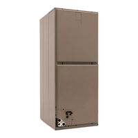
Johnson Controls AP36BX21 Manuals
Manuals and User Guides for Johnson Controls AP36BX21. We have
1
Johnson Controls AP36BX21 manual available for free PDF download: Installation And Maintenance Manual
Johnson Controls AP36BX21 Installation And Maintenance Manual (77 pages)
Brand:
Johnson Controls
| Category:
Air Handlers
| Size: 3 MB
Table of Contents
Table of Contents
3
Air Handler
5
Introduction
5
Safety
6
Figure 1. Return Air Duct Attachment and Component Location
7
Figure 2. Pressure Check
8
Figure 3. Dimensions and Duct Connection Dimensions
8
Unit Installation
9
Table 1. Dimensions
9
Figure 4. Typical Installation
11
Figure 5. Coil Blow off Wing Installation
12
Duct Work and Connections
13
Figure 7 Duct Attachment
14
Figure 6. Horizontal Suspension
14
Figure 8 Duct Work Transition
15
Electronic Expansion Valve
15
Refrigerant Line Connection
16
Condensate Drain Connections
18
Electric Heater Installation
18
Line Power Connections
19
Figure 9. Line Power Connections
19
Blower Speed Connections
20
Unit Data
20
Table 2. Physical and Electrical Data - Cooling Only
20
Figure 10. Factory Wired Blower Connections
20
Table 5. KW & MBH Conversions - for Total Power Input Requirement
21
Table 3. Electrical Data - Cooling Only
21
Table 4. Electrical Heat - Minimum Fan Speed
21
Table 6. Electric Heat Performance Data: 208/230-1-60 & 208/230-3-60
22
1Ph 6Hk(0,1)6500806
23
6Hk(0,1)6500206
23
6Hk(0,1)6500506
23
6Hk(0,1)6501006
23
6Hk(1,2)6501306
23
6Hk(1,2)6501506
23
6Hk(1,2)6501806
23
6Hk(1,2)6502006
23
Table 7. Electrical Data for Single Source Power Supply: 208/230-1-60
23
6Hk(1,2)6502506
24
Table 8. Electrical Data for Multi-Source Power Supply: 208/230-1-60
25
6Hk36501025
26
6Hk36501825
26
6Hk46502025
26
6Hk46502525
26
Table 9. Electrical Data for Single Source Power Supply: 208/230-1-60
26
Table 10. Electrical Data for Multi-Source Power Supply: 208/230-3-60
27
Table 11. Air Flow Data (CFM1)
28
Air System Adjustment
29
Figure 11. Duct Static Measurements
29
Maintenance
29
Figure 12. Drain Traps
30
Figure 13. Location of Coil Trapped and Plugged Drain Connections
30
Installation Veri Cation
30
DX Kit
31
Introduction
32
Safety Instructions
32
Before Installation
38
Figure 14. DX-Kit in the VRF System
38
Figure 15. Installation Space
42
Installation Location
42
Figure 16. Installation Dimensions
43
Installation Work
43
Figure 17. Mounting the Control Box
44
Figure 18. Mounting Valve Box
45
Figure 19. Details of Mounting Hole
45
Refrigerant Piping Work
46
Table 12. Piping Size
46
Figure 20. Piping Connections
47
Figure 21. Flare Dimensions
47
Figure 22. Applying Refrigerant Oil
48
Figure 23. Insulating Piping
48
Electrical Wiring
49
Figure 24. Electrical Wiring Diagram of Transformer (TF)
49
Figure 25. Electrical Wiring Connections: Heat Pump and Heat Recovery Systems
51
Figure 26. Positions of Electrical Wiring Connection
52
Figure 27. Reconnect Wiring
53
Figure 28. Wired Controller Connections
54
Figure 29. Wired Connections from the Control Box
55
Figure 30. Attaching Cable Holders to Air Handler
56
Figure 31. Wiring Holes of Air Handler
57
Figure 32. Thermistor Positions
58
Figure 33. Thermistor Connectors
59
Figure 34. Thermistor Installation with Details
60
Figure 35. Air Inlet and Outlet Thermistors
61
Figure 36. Positions of Air Inlet and Outlet Thermistors
62
Figure 37. Thermistor Extension Installation
62
Figure 38. Connection to Fan Motor
63
Figure 39. Connection to Fan Motor Inside Air Handler
64
Figure 40. Connection to Expansion Valve Box
65
Figure 41. Connection for Power Supply
66
Figure 42. Terminal Box Connection
67
Figure 43. Expansion Valve Box Terminal Block
68
Figure 44. Position of DIP Switches
69
Figure 45. Unit Setting
69
Figure 46. Capacity Code Setting (DSW3)
69
Figure 47. Refrigerant Cycle Setting
70
Figure 48. Test Run Menu
71
Test Run
71
Figure 49. Test Run: 2 Units
72
Figure 50. RUN Indicator
72
Cautions
74
Startup Sheet
75
Advertisement
Advertisement
Related Products
Johnson Controls AP36CX21
Johnson Controls AP18BX21
Johnson Controls AP24BX21
Johnson Controls AP30BX21
Johnson Controls AP48CX21
Johnson Controls AP48DX21
Johnson Controls AP60CX21
Johnson Controls AP60DX21
Johnson Controls AV Series
Johnson Controls AV-24B
Johnson Controls Categories
Controller
Air Conditioner
Thermostat
Control Unit
Irrigation System
More Johnson Controls Manuals
Login
Sign In
OR
Sign in with Facebook
Sign in with Google
Upload manual
Upload from disk
Upload from URL