Sign In
Upload
Manuals
Brands
JLG Manuals
Lifting Systems
601S
JLG 601S Telescopic Boom Lift Manuals
Manuals and User Guides for JLG 601S Telescopic Boom Lift. We have
1
JLG 601S Telescopic Boom Lift manual available for free PDF download: Service And Maintenance Manual
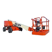
JLG 601S Service And Maintenance Manual (244 pages)
Brand:
JLG
| Category:
Lifting Systems
| Size: 18 MB
Table of Contents
A General
5
Bhydraulic System Safety
5
Maintenance
5
Table of Contents
7
Section 1. Specifications
17
Capacities
17
Fuel Tank
17
Hydraulic Oil Tank
17
Hydraulic System (Including Tank)
17
Torque Hub, Drive
17
Engine Crankcase
17
Component Data
17
Engine - Diesel (Liquid-Cooled)
17
Drive System
17
Swing System
18
Hydraulic Gear Pump (at 1800 RPM)
18
Auxiliary Power Pump
18
Hydraulic Filter - In-Line
18
Performance Data
18
Turning Radius (Outside)
18
Turning Radius (Inside)
18
Boom Elevation
18
Machine Weight Approximately
18
Machine Height (Stowed)
18
Test Notes
19
Torque Requirements
19
Lubrication
20
Ford LRG425 Engine
20
Deutz F3M1011F Engine
20
Hydraulic Oil
21
Lubrication Specifications
21
Pressure Settings
21
Rexroth Valve
21
Cylinder Specifications
22
Major Component Weights
22
Critical Stability Weights
22
Serial Number Locations
23
Lubrication Diagram
24
Lubrication Chart
25
Section 2 - General
27
Machine Preparation, Inspection, and Maintenance
27
General
27
Preparation, Inspection, and Maintenance
27
Pre-Start Inspection
27
Pre-Delivery Inspection and Frequent Inspection
27
Annual Machine Inspection
27
Preventative Maintenance
27
Service and Guidelines
28
General
28
Safety and Workmanship
28
Cleanliness
28
Components Removal and Installation
28
Component Disassembly and Reassembly
29
Pressure-Fit Parts
29
Bearings
29
Gaskets
29
Bolt Usage and Torque Application
29
Hydraulic Lines and Electrical Wiring
29
Hydraulic System
29
Lubrication
29
Battery
29
Lubrication and Servicing
29
Lubrication and Information
30
Hydraulic System
30
Hydraulic Oil
30
Changing Hydraulic Oil
30
Lubrication Specifications
30
Cylinder Drift Test
31
Platform Drift
31
Cylinder Drift
31
Pins and Composite Bearing Repair Guidelines
31
Welding on JLG Equipment
32
Do the Following When Welding on JLG Equipment
32
Do NOT Do the Following When Welding on JLG Equipment
32
Applying Silicone Dielectric Compound to Electrical Connections
32
AMP Connector
33
Applying Silicone Dielectric Compound to AMP Connectors
33
Assembly
33
Connector Assembly Figure 1
33
Connector Assembly Figure 2
33
Connector Assembly Figure 3
33
Connector Assembly Figure 4
33
Disassembly
35
Wedge Lock
35
Service - Voltage Reading
35
Connector Installation
36
Inspection and Preventive Maintenance Schedule
37
Section 3. Chassis & Turntable
41
Torque Hub, Drive
41
Disassembly
41
Cleaning and Inspection
41
Repair
41
Torque Hub, Drive (Fairfield)
41
Assembly
44
Torque Hub, Drive (Fairfield)
49
Torque Hub, Drive (Auburn Gear)
50
Disassembly
50
Assembly
50
Torque Hub, Drive (Auburn Gear)
51
Drive Brake - Ausco
52
Disassembly
52
Inspection
52
Assembly
52
Drive Brake Assembly (Ausco)
53
Drive Brake - Mico
54
Disassembly
54
Assembly
54
Drive Brake - Mico
55
Bleeding
56
Drive Motor (Prior to S/N 85132)
57
Spare Parts Kits
57
Replacing the Drive Shaft Seal
58
Disassembly and Assembly
59
Assembly Notes
63
Taper Roller Bearing Initial Tension
63
Flow Control Pilot Valves
64
Testing and Setup
65
Drive Motor Adjustment Procedure (Prior to S/N 85132)
66
Drive Motor Adjustment
66
Drive Motor (S/N 85132 to Present)
67
Description
67
Shaft Seal Replacement
67
Endcap
67
Loop Flushing Valve
68
Troubleshooting
69
Disassembly
70
Valve Plate & Rear Shaft Bearing
71
Shaft Seal
72
Shaft & Front Bearing
72
Cylinder Kit Assembly
72
Swash Plate & Servo Piston
73
Inspection
74
Assembly
76
Swash Plate and Journal Bearing
77
Shaft and Front Bearing
78
Cylinder Kit Installation
78
Servo Spring and Minimum Angle Stop
78
Valve Plate and Rear Bearing
79
End Cap
79
Shaft Seal
80
Initial Start-Up Procedures
81
Free Wheeling Option
81
To Disengage Drive Motors and Brakes (Free Wheel) for Towing, Etc
81
To Engage Drive Motors and Brakes (Normal Operation)
82
Oscillating Axle Bleeding Procedure and Lockout Test
83
Lockout Cylinder Bleeding
83
Oscillating Axle Lockout Test
83
Oscillating Valve Adjustment
83
Drive Manual Control Valve
83
Steer Adjustments
84
Swing Hub
85
Adjustment Procedures
85
Swing Bearing
85
Turntable Bearing Mounting Bolt Condition Check
85
Wear Tolerance
86
Swing Bearing Replacement
86
Swing Bearing Tolerance Measuring Point
86
Swing Bearing Torque Value
89
Swing Brake - Ausco
89
Disassembly
89
Inspection
90
Assembly
90
Swing Brake Assembly (Ausco)
91
Swing Motor
92
Disassembly
92
End Cap Removal
92
Reassembly
93
Motor Timing
94
Swing Motor
95
Tilt Alarm Switch (Machines with External Tilt Sensor)
96
Manual Adjustment
96
Spark Arrester Cleaning Instructions
96
Dual Fuel System
96
Changing from Gasoline to LP Gas
96
Changing from LP Gas to Gasoline
97
Electric Governor Installation and Adjustments - Ford Engine
97
General
97
Quick-Start Installations
97
Mounting-Actuator
97
Linkage
97
Mounting-Controller
98
Wiring
98
Check-Out and Initial Start-Up Procedures
100
Multi-Turn Adjustment (High Engine, MID Engine, Overspeed, Starter Lockout)
100
Single-Turn Adjustment (Gain, Factory Adjust)
100
Troubleshooting
101
Throttle Checks and Adjustments - Deutz Engine (Prior to S/N 61306)
103
General
103
Procedure
104
Controller Status
104
Failure Modes
104
Automatic Choke Adjustment - Ford Engine
105
Cold Weather Starting Difficulty
106
Checking the Carburetor
106
Checking the Ignition
107
Checking the Fuel
107
Ford EFI Engine (Machines after S/N 58209)
108
Performing Diagnostics
108
EFI Diagnostics (S/N 58209 to S/N 60188)
108
Engine Module and Sensors
109
ECM Diagnostic Trouble Codes
110
EPM Diagnostic Trouble Codes
111
ECM/EPM Identification
122
Fuel System
123
Typical Fuel System
124
Section 4. Boom & Platform
129
Boom Maintenance
129
Removal
129
Disassembly Boom Sections
130
Disassembly of Sheave Assembly
131
Boom Assembly Cutaway - Sheet 1 of 2
132
Boom Assembly Cutaway - Sheet 2 of 2
133
Inspection
134
Assembly
135
Installation
137
Boom Rope Torquing Procedures
137
Torque Procedures
137
Wear Pads
138
Main Boom
138
Wire Rope
139
Inspection
139
Three Month Inspection
139
Year or 7000 Hour Replacement
139
Additional Replacement Criteria
139
Limit Switches and Cam Valve Adjustment
140
Limit Switch Functional Check
141
Rotator - Helac
142
Disassembly
142
Inspection
143
Assembly
144
Rotator Assembly (Helac)
145
Drive Card Setup Procedures
146
Lift, Swing, and Drive Cards
146
Flow Control Card
146
Foot Switch Adjustment
147
Section 5. Hydraulics
149
Cylinders - Theory of Operation
149
Systems Incorporating Double Acting Cylinders
149
Systems Incorporating Holding Valves
149
Valves - Theory of Operation
149
Solenoid Control Valve - Rexroth
149
Relief Valves
149
Cylinder Checking Procedure
149
Cylinders Without Counterbalance Valves - Master Cylinder and Steer Cylinder
149
Cylinders with Dual Counterbalance Valves
150
Cylinder Repair
150
Disassembly
150
Cap Screw Removal
151
Cleaning and Inspection
152
Assembly
153
Piston Seal Kit Installation
154
Rod Assembly Installation
155
Cylinder Removal and Installation
156
Main Boom Telescope Cylinder Removal
156
Main Boom Telescope Cylinder Installation
156
Boom Lift Cylinder Removal
157
Boom Lift Cylinder Installation
157
Variable Displacement Pump (M46 Series)
158
Troubleshooting
158
Subject - Section, Paragraph
156
Troubleshooting - System Operating Hot
159
Troubleshooting - System Response Is Sluggish
160
Inspections and Adjustments
161
Minor Repair and Replacement
164
Pressure Setting Procedures
168
Main Relief, Steer, Swing and Lift down
168
Platform Level
168
Wheel Steer (if Equipped)
168
Main Control Valve - Sheet 1 of 2
169
Main Control Valve - Sheet 2 of 2
170
Main Control Valve Torque Values
171
Directional Control Valve
172
Hydraulic Pump W/Hayes Pump Drive Coupling Lubrication
172
Hydraulic Component Start-Up Procedures and Recommendations
172
Section 6. Jlg Control System (Ade)
175
Introduction
175
EPBCS Block Diagram
176
To Connect the JLG Control System Analyzer
177
Using the Analyzer
177
Analyzer Connecting Points
178
Changing the Access Level of the Hand Held Analyzer
179
Control Module and Fault Code Indicator Location
180
Adjusting Parameters Using the Hand Held Analyzer
181
Machine Setup
182
Level Vehicle Description
182
Machine Personality Settings
186
Help Fault Codes, Displayed Faults, and Descriptions - Prior to S/N 66939
188
Help Fault Codes, Displayed Faults, and Descriptions - S/N 66939 to Present
192
Machine Configuration Programming Information Prior to Software Version P5.3
203
Machine Configuration Programming Information Software Version P5.3 to Present
207
Fault Code Listing
212
Analyzer Diagnostics Menu Structure
218
Diagnostic Menu Descriptions
221
Section 7 - Schematics
223
General
223
Troubleshooting
223
Hydraulic Circuit Checks
223
Electrical Components Installation (Prior to S/N 62137) - Sheet 1 of 2
224
Electrical Components Installation (Prior to S/N 62137)- Sheet 2 of 2
225
Electrical Components Installation (S/N 62137 to Present)-Sheet 1 of 2
226
Electrical Components Installation (S/N 62137 to Present)-Sheet 2 of 2
227
Electrical Schematic - Deutz Engine - Sheet 1 of 2
228
Electrical Schematic - Deutz Engine - Sheet 2 of 2
229
Electrical Schematic - Ford Dual Fuel Engine - Sheet 1 of 2
230
Electrical Schematic - Ford Dual Fuel Engine - Sheet 2 of 2
231
Electrical Schematic - Ford EFI Engine - Sheet 1 of 2
232
Electrical Schematic - Ford EFI Engine - Sheet 2 of 2
233
Electrical Schematic - ADE Machines - Sheet 1 of 4
234
Electrical Schematic - ADE Machines - Sheet 2 of 4
235
Electrical Schematic - ADE Machines - Sheet 3 of 4
236
Electrical Schematic - ADE Machines - Sheet 4 of 4
237
Hydraulic Schematic - Sheet 1 of 4
238
Hydraulic Schematic - Sheet 2 of 4
239
Hydraulic Schematic - Sheet 3 of 4
240
Hydraulic Schematic - Sheet 4 of 4
241
Advertisement
Advertisement
Related Products
JLG 660SJC
JLG 642
JLG 680S
JLG Skytrak 6036
JLG 600S
JLG 600SJ
JLG 600A
JLG 600AJ
JLG 600SJC
JLG 600SC
JLG Categories
Boom Lifts
Lifting Systems
Scissor Lifts
Construction Equipment
Work Light
More JLG Manuals
Login
Sign In
OR
Sign in with Facebook
Sign in with Google
Upload manual
Upload from disk
Upload from URL