Sign In
Upload
Manuals
Brands
Jetter Manuals
Data Loggers
JVM-104-O16
Jetter JVM-104-O16 Manuals
Manuals and User Guides for Jetter JVM-104-O16. We have
2
Jetter JVM-104-O16 manuals available for free PDF download: User Manual
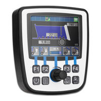
Jetter JVM-104-O16 User Manual (66 pages)
Brand:
Jetter
| Category:
Data Loggers
| Size: 3.45 MB
Table of Contents
Table of Contents
3
1 Introduction
7
Information on this Document
7
Typographical Conventions
7
2 Safety
8
General Information
8
Purpose
8
Intended Use
8
Usage Other than Intended
8
Warnings Used in this Document
8
3 Product Description
9
Design
9
Functions
9
Fig. 1 Device Configuration
9
Fig. 2 Nameplate
9
Nameplate
10
Scope of Delivery
10
4 Technical Specifications
11
Dimensions
11
Electrical Properties
11
Mechanical Specifications
11
Fig. 3 Dimensions (in MM)
11
Tab. 1 Power Supply VBAT_ECU
11
Environmental Conditions
12
Display
12
Acoustic Signal Generator
12
Ports and Interfaces
12
CAN Port
12
Tab. 2 Mechanical Specifications
12
Tab. 3 Environmental Conditions
12
Tab. 4 Technical Data - Display
12
Tab. 5 Acoustic Signal Generator
12
Tab. 23 Protocol
12
USB Interface
13
Ethernet Interface
13
Tab. 6 CAN Interfaces
13
Tab. 7 Specification - CAN Bus Cable
13
Tab. 8 Line Lengths
13
Tab. 9 USB Interface
13
Tab. 10 Ethernet Interface
13
EMI Values
14
Tab. 11 RS-232 Interface
14
Tab. 12 Pulses to ISO 7637-2
14
Tab. 13 Irradiation to ISO 11452
14
Tab. 14 ESD en 61000-4-2
14
5 Mechanical Installation
15
Requirements for the Installation Location
15
Fig. 4 Space Requirements for Installation Work (in MM)
15
Tab. 15 Unsuitable Installation Locations
15
Preparing for Installation
16
Fig. 5 Dimensions (in MM)
16
Tab. 16 Mounting Accessories
16
Installing the HMI
17
Fig. 6 Installation Drawing
17
Fig. 7 Mounted HMI - Top View
18
Fig. 8 Installing the Strain Relief
18
6 Electrical Connection
19
Pin Assignment of Deutsch Connector
20
Fig. 9 Deutsch Connector, 12 Pins
20
Pin Assignment of M12 Connector
21
Fig. 10 M12 Connector, 4 Pins
21
7 Programming
22
Abbreviations, Module Register Properties and Formats
22
Tab. 17 Abbreviations
22
Tab. 18 Module Register Properties
22
Tab. 19 Numerical Formats
22
Tab. 20 Jetsym Sample Programs
22
Canopen® STX API
23
STX Functions
23
Heartbeat Monitoring
24
Canopen® Object Dictionary
24
Sae J1939 Stx Api
25
STX Functions
25
Serial Interface RS-232
26
Operating Principle
26
Fig. 11 Block Diagram - Serial Interface
26
Tab. 21 Elements of the Serial Interface
27
Registers - Description
28
Tab. 22 Register Numbers of the Serial Interface
29
Tab. 25 Number of Data Bits Per Character
29
Tab. 26 Stop Bits
29
Tab. 27 Parity
30
Tab. 28 Activating the Serial Interface
30
Tab. 29 Sending Buffer
30
Tab. 30 Sending Buffer Filling Level
30
Tab. 31 Receive Buffer, 8 Bits (Without Deleting the Character on Reading)
31
Tab. 32 Receive Buffer, 8 Bits (with Deleting the Character on Reading)
31
Tab. 33 Receive Buffer Filling Level
31
Tab. 34 Receive Buffer, 16-Bit, Little Endian
31
Tab. 35 Receive Buffer; 16-Bit; Big Endian
32
Tab. 36 Receive Buffer, 32-Bit, Little Endian
32
Tab. 37 Receive Buffer; 32-Bit; Big Endian
32
Programming
33
Activating the Serial Interface
33
Configuring the Serial Interface
33
Sending Characters
33
Receiving Characters
33
Tab. 38 Error Counter
33
Sending Texts
34
Sending Values
34
Receiving Values
34
Real-Time Clock
35
File System
35
Directories
35
FTP Server
35
Storage Options - Overview
36
Types of Program and Data Memory
36
Operating System Memory
36
File System Memory
36
Application Program Memory
37
Flash Disk
37
Tab. 39 Flash Disk Capacity
37
USB Flash Drive
38
Storing Registers and Variables
38
Special Registers
38
Flag
38
Control Elements
39
Input Keys
39
Tab. 40 Input Key Registers
39
Tab. 41 Virtual Key Codes
39
Digipot
40
User-Programmable IP Interface
41
Monitoring Interface Activities
41
Automatic Copying of Controller Data
42
Loading the Autostart Function
42
Tab. 42 Relevant Directories
42
Executing the Autostart Function
43
Terminating the Autostart Mode
43
Autostart.bat - Structure
43
Example of a Command File
43
Data Files
44
Operating System Update
45
Updating the Operating System Via Programming Tool
45
Performing the Operating System Update Via FTP
46
Performing the Operating System Update Via USB
46
Performing an Operating System Update Via the Device Website
47
Fig. 12 Accessing the Device Web Site
47
Performing an os Update Via \App
48
Fig. 13 Device Website - Proxy Settings
48
Fig. 14 the Updating Site
48
Performing an os Update Via Jeteasydownload
49
Application Program
49
Fig. 15 Subdirectory \App
49
8 Registers - Overview
51
Default Address on the Canopen® Bus
51
General Overview - Registers
51
I/Os - General Overview
51
Flags - General Overview
51
Electronic Nameplate
51
Electronic Name Plate (Device as a Whole)
52
Configuration
52
Ethernet
52
Can
53
Serial Interface RS-232
53
Flash Memory
53
System Information
53
USB Flash Drive
54
General System Registers
54
Application Program
55
Networking Via Jetip
56
Modbus/Tcp Server
57
File System/Data File Function
57
User-Programmable IP Interface
57
Application Registers
57
Display
57
Flag
58
Real-Time Clock
59
9 Maintenance and Repairs
61
Maintenance, Repairs and Disposal
61
Storage and Shipment
61
Tab. 43 Accessories
63
List of Figures
64
Advertisement
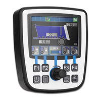
Jetter JVM-104-O16 User Manual (79 pages)
HMI
Brand:
Jetter
| Category:
Recording Equipment
| Size: 1.06 MB
Table of Contents
Table of Contents
3
Introduction
6
Information on this Document
6
Typographical Conventions
6
Safety
7
General Information
7
Purpose
7
Intended Use
7
Usage Other than Intended
7
Warnings Used in this Document
8
Product Description
9
Design
9
Product Features
9
Fig. 1 Design
9
Fig. 2 Nameplate
10
Scope of Delivery
10
Nameplate
10
Technical Data
11
Dimensions
11
Mechanical Specifications
11
Fig. 3 Dimensions in MM
11
Tab. 1 Mechanical Specifications
11
Tab. 4 Specification - CAN Bus Cable
12
Tab. 3 CAN Interfaces
12
Tab. 2 Power Supply VBAT_ECU
12
Ports and Interfaces
12
Electrical Properties
12
Tab. 5 Cable Lengths
13
Tab. 6 USB Port
13
Tab. 7 Ethernet Interface Specification
13
Tab. 8 RS-232 Interface Specification
13
Tab. 11 Acoustic Signal Generator
14
Tab. 10 Technical Data - Display
14
Acoustic Signal Generator
14
Tab. 9 Environmental Conditions
14
Display
14
Environmental Conditions
14
EMI Values
15
Tab. 12 Pulses ISO 7637-2
15
Tab. 13 Irradiation ISO 11452
15
Tab. 14 ESD en 61000-4-2
15
Mechanical Installation
16
Requirements for the Installation Location
17
Fig. 4 Space Requirements for Installation Work (in MM)
17
Tab. 15 Unsuitable Installation Locations
17
Preparing for Installation
18
Fig. 5 Mounting Surface Dimensions in MM
18
Installing the HMI
19
Fig. 6 Installation Drawing
19
Fig. 8 Installing the Strain Relief
20
Fig. 7 Mounted HMI - Top View
20
Electrical Connection
21
Pin Assignment
21
Deutsch Connector - Voltage Supply, CAN, USB, RS-232
21
M12 Plug - Ethernet
22
Fig. 9 Deutsch Connector, 12 Pins
22
Fig. 10 M12 Plug, 4-Pin
22
Operating System Update of the HMI
23
Operating System
23
Identification and Configuration
23
Tab. 16 Jeteasydownload Parameters
25
Fig. 11 Web Interface Access
27
Fig. 12 Proxy Settings on the Web Interface
28
Fig. 13 Web Interface Update
28
Fig. 14 Directory \App
29
File System
30
Fig. 15 Bootupscreen.bmp File in the \System Directory
31
Features
31
Changing the Boot Screen
31
Programming
33
Abbreviations, Module Register Properties and Formats
33
Tab. 17 Abbreviations
33
Tab. 18 Module Register Properties
33
Tab. 19 Numerical Formats
33
Tab. 20 Jetsym Sample Programs
33
Canopen STX API
34
STX Functions
34
Heartbeat Monitoring
35
Tab. 21 Supported STX Functions
35
Canopen Object Directory
36
Sae J1939 Stx Api
37
STX Functions
37
Fig. 16 Block Diagram - Serial Interface
39
Operating Principle
39
Serial Interface RS-232
39
Tab. 22 Elements of the Serial Interface
40
Registers - Description
42
Tab. 23 Register Numbers of the Serial Interface
42
Tab. 24 Protocol
42
Tab. 25 Baud Rate
43
Tab. 26 Number of Data Bits Per Character
43
Tab. 27 Stop Bits
43
Tab. 28 Parity
43
Tab. 29 Activating the Serial Interface
44
Tab. 30 Sending Buffer
44
Tab. 31 Sending Buffer Filling Level
44
Tab. 32 Receive Buffer, 8 Bits (Without Deleting the Character on Reading)
45
Tab. 33 Receive Buffer, 8 Bits (with Deleting the Character on Reading)
45
Tab. 34 Receive Buffer Filling Level
45
Tab. 37 Receive Buffer, 32-Bit, Little Endian
46
Tab. 36 Receive Buffer; 16-Bit; Big Endian
46
Tab. 35 Receive Buffer, 16-Bit, Little Endian
46
Programming
48
Real-Time Clock
50
FTP Server
51
File System Memory
52
Application Program Memory
52
Operating System Memory
52
Storage Options - Overview
52
Special Registers
53
Flag
53
Storing Registers and Variables
54
Control Elements
54
Input Keys
54
Digipot
55
User-Programmable IP Interface
57
Monitoring Interface Activities
58
Automatic Copying of Controller Data
59
Loading the Autostart Function
60
Terminating the Autostart Mode
60
Autostart.bat - Structure
60
Executing the Autostart Function
60
Example of a Command File
61
Data Files
62
Saving and Loading an Application Program
63
Registers - Overview
64
Fig. 17 WEEE Icon - Crossed-Out Trash Can
72
Maintenance
72
Return and Disposal
72
Repairs
72
Storage and Shipment
73
Service
74
Customer Service
74
Spare Parts and Accessories
75
Accessories
75
List of Figures
76
Advertisement
Related Products
Jetter JCM-501-E00
Jetter JVM-104
Jetter JVM-104-O15
Jetter JVM-104-O09
Jetter JVM-104-O08
Jetter JVM-104-O13
Jetter JVM-104-K00-O02
Jetter JVM-507B - HMI
Jetter JVM-206-K00-O21
Jetter JVM-407B-HMI
Jetter Categories
Control Unit
Controller
Amplifier
Computer Hardware
Recording Equipment
More Jetter Manuals
Login
Sign In
OR
Sign in with Facebook
Sign in with Google
Upload manual
Upload from disk
Upload from URL