Sign In
Upload
Manuals
Brands
iWave Manuals
Control Unit
iW-RainboW-G21M
iWave iW-RainboW-G21M Manuals
Manuals and User Guides for iWave iW-RainboW-G21M. We have
2
iWave iW-RainboW-G21M manuals available for free PDF download: Hardware User's Manual, User Manual
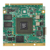
iWave iW-RainboW-G21M Hardware User's Manual (92 pages)
RZ/G1H Qseven SOM
Brand:
iWave
| Category:
Control Unit
| Size: 6 MB
Table of Contents
Table of Contents
4
1 Introduction
7
Purpose
7
Qseven SOM Overview
7
List of Acronyms
7
Table 1: Acronyms & Abbreviations
7
Terminlogy Description
9
References
9
Table 2: Terminology
9
Important Note
10
2 Architecture and Design
11
RZ/G1H Qevensom Block Diagram
11
Figure 1: RZ/G1H Qseven SOM Block Diagram
11
RZ/G1H Qsevensom Features
12
Rz/G1H Cpu
15
Figure 2: RZ/G1H CPU Simplified Block Diagram
15
Memory
16
Ddr3 Sdram
16
SPI nor Flash
16
Emmc Flash
17
RTC Controller
17
Qseven PCB Edge Connector
18
Figure 3: Qseven PCB Edge Connector
18
Gigabit Ethernet
19
Table 3: Compatible Magnetics
19
Pcie Interface
20
USB 3.0 Host Interface
20
SATA Interface (Optional)
21
USB 2.0 Host Interface
21
USB 2.0 OTG Interface
21
LVDS Display Interface
22
SD Interface
22
HDMI Interface (Optional)
23
I2S Audio Interface
23
CAN Interface
24
DATA UART Interface
24
SPI Interface
24
GPIO Interface
25
I2C Interface
25
PWM Interface
25
Manufacturing/Debug UART Interface
26
Power Control Signal
26
Power Input
26
Reset Signal
26
Table 4: Qseven PCB Edge Connector Pin Assignment
27
Expansion Connector1 Interfaces
42
Figure 4: Expansion Connector1
42
Parallel Camera Interfaces
43
Table 5: Parallel Camera Interface Pin Assignment on Expansion Connector1
43
Table 6: Expansion Connector1 Pin Assignment
44
Expansion Connector2 Interfaces
50
Figure 5: Expansion Connector2
50
10/100Mbps Ethernet
51
I2S Audio Interface
51
Table 7: Compatible Magnetics
51
CAN Interface
52
Data UART Interface
52
PWM Interface
53
SPI Interface
53
Table 8: Expansion Connector2 Pin Assignment
54
Other Features
60
JTAG Header
60
Figure 6: JTAG Header
60
Table 9: JTAG Header Pin Assignment
61
SPI Programming Header
62
Figure 7: SPI Programming Header
62
Table 10: SPI Programming Header Pin Assignment
62
Power in Connector (Optional)
63
Figure 8: 2Pin Power Connector
63
Table 11: Power in Connector - BOM
63
RZ/G1H Pin Multiplexing on Qseven Edge and Expansion Connectors
64
Table 12: RZ/G1H CPU IOMUX for Qseven Edge Connector Interfaces
64
Table 13: RZ/G1H CPU IOMUX for Expansion Connector1 Interfaces
69
Table 14: RZ/G1H CPU IOMUX for Expansion Connector2 Interfaces
72
RZ/G1H CPU Reference Schematic
74
3 Technical Specification
79
Electrical Characteristics
79
Power Input Requirement
79
Table 15: Power Input Requirement
79
Power Input Sequencing
80
Figure 9: Qseven SOM Power Sequence
80
Table 16: Power Sequence Timing
80
Power Consumption
81
Table 17: Power Consumption
81
Environmental Characteristics
82
Environmental Specification
82
Heat Sink/Spreader
82
Table 18: Environmental Specification
82
Figure 10: Heat Sink Dimensions
83
Rohs Compliance
84
Electrostatic Discharge
84
Figure 11: Heat Spreader Dimensions
84
Mechanical Characteristics
85
Qseven SOM Mechanical Dimensions
85
Figure 12: Mechanical Dimension of Qseven SOM- Top View
85
Figure 13: Mechanical Dimension of RZ/G1H Qseven SOM- Bottom View
86
Figure 14: Mechanical Dimension of RZ/G1H Qseven SOM- Side View
86
Guidelines to Insert the Qseven SOM into Carrier Board
87
Figure 15: Qseven Module Insertion Procedure
87
4 Ordering Information
88
Table 19: Orderable Product Part Numbers
88
5 Appendix I
89
5. Appendix I
89
Figure 16: Configuration Switches
89
RZ/G1H Qseven SOM Configuration Switches
89
Table 20: SOM Configuration Switches
89
6 Appendix II
90
6. Appendix II
90
RZ/G1H SPI Programmer Board
90
Figure 17: RZ/G1H SPI Programming Board
90
7 Appendix III
91
7. Appendix III
91
RZ/G1H Qseven SOM Development Platform
91
Figure 18: RZ/G1H Qseven SOM Development Platform with Add on Module
91
Advertisement
iWave iW-RainboW-G21M User Manual (83 pages)
RZ/G1H Qseven SOM
Brand:
iWave
| Category:
Control Unit
| Size: 2 MB
Table of Contents
Table of Contents
4
1 Introduction
8
Purpose
8
Scope
8
List of Acronyms
8
Table 1: Acronyms & Abbreviations
8
2 Board Support Package
10
Bsp Driver Details
10
BSP Supported Features
10
Driver Source Description
10
Table 2: Driver Source Path
10
Device Tree Source Description
14
Table 3: Device Tree Source
14
Bsp Yocto Compilation
15
Host Requirements
15
Host Setup
15
Host Package Installation
15
Yocto Project Setup
16
Yocto Build
18
U-Boot
20
Linux Kernel
21
Cross-Compiler Build
22
Bsp Standalone Compilation
23
Loader
24
U-Boot
25
Linux Kernel
26
Bsp Customization
28
I2C Device
28
Uart
29
Gpio
29
Lvds
30
Primary Display
31
Boot Logo Configuration
31
USB OTG Host Configuration
31
Yocto Package
32
3 Binary Programming
34
Jtag Programming
34
Requirements
34
Figure 1: Boot Device Memory Layout
34
Booting Via JTAG
35
U-Boot Programming
36
Manual Programming
37
Requirements
37
SD Card Preparation
37
Emmc Partition
38
U-Boot Programming
40
Kernel Programming
41
Bootable Sd Card
42
Requirements
42
SD Card Partition
42
SD Card Programming
45
4 U-Boot Testing and Boot Configuration
46
Basic Commands
46
Ram Test
47
Sd/MMC Test
48
Spi nor Flash Test
49
Usb Test
49
Ethernet Test
50
TFTP & NFS Host PC Setup
50
Environment Variables Settings
52
Emmc Boot
52
Standard SD Boot
52
TFTP & NFS Boot
53
HDMI Resolution Setting
53
VIN Camera Selection
54
SPI/VIN2 Camera Selection
54
Default Environment Variable
54
5 Linux Peripheral Testing
55
Block Devices Test
55
Testing Device Requirements
55
Block Device Test
56
USB OTG as Device
57
SPI nor Flash Test
58
Network Devices Test
59
Testing Device Requirements
59
Ethernet Test
59
Ethernet Speed and Duplex Settings
61
File Transfer Using TFTP Server
61
Folder Mount from NFS
61
CAN Test
62
Display Devices Test
63
Testing Device Requirements
63
LCD Test
63
HDMI Test
63
Figure 2: Lcd -Yocto Gui
63
Figure 3: Hdmi -Yocto Gui
63
Qseven LVDS Control Test
64
PWM Brightness Test
64
Hid Devices Test
65
Testing Device Requirements
65
Mouse Test
65
Keyboard Test
65
Touch Screen Test
66
Figure 4: Yocto Home Screen
66
Figure 5: Yocto Menu Selection
66
Figure 6: Yocto Touch Calibration Icon
67
Figure 7: Yocto Touch Calibration
67
Uart Test
68
Pcie Device Test
69
Rtc Test
69
Multimedia Test
70
Testing Device Requirements
70
Audio Test
70
Camera Test
71
Table 4: Camera Input Resolution Settings
71
GPU Test
72
Gstreamer Test
73
Gpio Testing
75
Thermal Trip LED Test
75
Table 5: Gpio Device Node
76
Processor Cooling Fan Control Test
77
Wayland
78
Camera Test
78
GPU Test
79
Table 6: Wayland - Camera Input Resolution Settings
79
Gstreamer Test
80
6 APPENDIX - Frequently Asked Questions
81
Table 7: Som Switch Settings
82
Advertisement
Related Products
iWave iW-RainboW-G17M
iWave iW-RainboW-G34M
iWave iW-RainboW-G18M
iWave iW-RainboW-G50M i.MX 93
iWave iW-RainboW-G50M i.MX 91
iWave iW-RainboW-G53M
iWave iW-RainboW-G54M STM32MP13 Series
iWave iW-RainboW-G46M
iWave i.MX 8M Plus Quad Lite
iWave iW-RainboW-G15S
iWave Categories
Motherboard
Computer Hardware
Single board computers
Control Unit
Microcontrollers
More iWave Manuals
Login
Sign In
OR
Sign in with Facebook
Sign in with Google
Upload manual
Upload from disk
Upload from URL