Sign In
Upload
Manuals
Brands
iWave Manuals
Microcontrollers
IW-G35D-19EG-4E004G-E008G-LCF
iWave IW-G35D-19EG-4E004G-E008G-LCF Kit Manuals
Manuals and User Guides for iWave IW-G35D-19EG-4E004G-E008G-LCF Kit. We have
1
iWave IW-G35D-19EG-4E004G-E008G-LCF Kit manual available for free PDF download: Hardware User's Manual
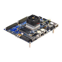
iWave IW-G35D-19EG-4E004G-E008G-LCF Hardware User's Manual (110 pages)
Zynq Ultrascale+ MPSoC (ZU11/17/19EG) SOM Development Platform
Brand:
iWave
| Category:
Microcontrollers
| Size: 7 MB
Table of Contents
Table of Contents
4
Introduction
8
Purpose
8
Overview
8
List of Acronyms
8
Table 1: Acronyms & Abbreviations
8
References
10
Table 2: Terminology
10
Architecture and Design
11
Zynq Ultrascale+ Mpsoc (ZU11/17/19EG) SOM Carrier Board Block Diagram
11
Figure 1: Zynq Ultrascale+ Mpsoc (ZU11/17/19EG) SOM Carrier Board Block Diagram
11
Zynq Ultrascale+ Mpsoc (ZU11/17/19EG) SOM Carrier Board Features
12
Board to Board Connectors
14
Board to Board Connector1
14
Figure 2: Board to Board Connector1
14
Board to Board Connector2
15
Figure 3: Board to Board Connector2
15
Board to Board Connector3
16
Figure 4 Board to Board Connector3
16
Board to Board Connector4
17
Figure 5 Board to Board Connector4
17
PS Interface Features
18
PS-GTR Transceivers
18
Figure 6: PS-GTR External Switch Connectivity
18
Figure 7: PS-GTR Lane Selection Switch
19
Table 3: PS-GTR Lane Selection Switch Setting
19
Figure 8: Pcie X4 Connector
20
Table 4: Pcie X4 Connector Pin Assignment
21
Figure 9: Display Port Connector
23
Figure 10: USB Type-C Connector
25
Table 5: USB Typec Pin Assignment
26
Figure 11: M.2 SATA Connector (Key M)
27
Table 6: M.2 SATA Connector Pin Assignment
28
Gigabit Ethernet Port1
30
Figure 12: Gigabit Ethernet Connector1
30
Gigabit Ethernet Port2
31
Figure 13: Gigabit Ethernet Connector2
31
USB2.0 OTG Port
32
Figure 14: USB OTG Connector
32
Standard SD Port
33
Figure 15: Standard SD Connector
33
CAN0 Header
34
Figure 16: CAN0 Header
34
Table 7: CAN0 Header Pin Assignment
34
Debug UART
35
Figure 17: Debug UART Connector
35
Interface Features
36
GTH High Speed Transceivers
36
Figure 18: SFP+ Connector with Cage
37
Table 8: SFP+ Connector Pin Assignment
38
Figure 19: SDI Video in HD BNC Connector
39
Figure 20: SDI Video out HD BNC Connector
40
Figure 21 HDMI in Connector
41
Figure 22 HDMI out Connector
42
GTY High Speed Transceivers
43
Figure 23 QSFP28/QSFP+/QSFP+ Connector with Cage
43
Table 9 QSFP28/QSFP+/QSFP Connector Pin out
44
Figure 24 Firefly Connector
46
Table 10 Firefly Data Connector Pin out
47
Table 11 Firefly Power Connector Pin out
48
Pmod Host Port Connectors
49
Figure 25: Pmod Host Port Connectors
49
Table 12: Pmod Connector1 Pin Assignment
50
Table 13: Pmod Connector2 Pin Assignment
50
Figure 26: SMA Connectors
51
Table 14: SMA Connector Pin Assignment
51
FMC HPC Connector
52
Figure 27: FMC Connector
52
Figure 28: FMC HPC Connector Pin out
53
Table 15: FMC HPC Connector Pin Assignment
54
FMC+ HPC Connector
67
Figure 29: FMC+ Connector
67
Figure 30: FMC+ HPC Connector Pin out
68
Table 16: FMC+ HPC Connector Pin Assignment
69
Additional Features
88
Clock Synthesizers
88
Table 17: Clock Synthesizer 1 Output Clocks
88
Table 18 Clock Synthesizer 2 Output Clocks
89
JTAG Connector
90
Figure 31: JTAG Connector
90
Table 19: JTAG Header Pin Assignment
91
IO Expanders
92
Table 20 IO EXPANDER 1 Output
92
Table 21 IO EXPANDER 2 Output
93
Table 22 IO EXPANDER 3 Output
94
I2C Expander
95
Figure 32 I2C Tree
95
GPIO Header
96
Figure 33: GPIO Header
96
Table 23: GPIO Header Pin Assignment
96
Power ON/OFF Switch
98
Figure 34: Power On/Off Switch
98
Reset Switch
99
Figure 35: Reset Switch
99
RTC Coin Cell Holder
100
Figure 36: RTC Coin Cell Holder
100
Fan Header
101
Figure 37: 12V-Fan Header
101
Table 24: 12V Fan Header Pinout
101
Technical Specification
102
Power Input Requirement
102
Figure 38: Power Jack
102
Table 25: Power Input Requirement
102
Power Output Specification
103
Table 26: Power Output Specification
103
Environmental Characteristics
104
Environmental Specification
104
Rohs Compliance
104
Electrostatic Discharge
104
Table 27: Environmental Specification
104
Mechanical Characteristics
105
Carrier Board Mechanical Dimensions
105
Figure 39: Carrier Board Mechanical Dimension - Top View
105
Figure 40: Carrier Board Mechanical Dimension - Side View
106
Guidelines to Insert the Zynq Ultrascale+ Soc SOM into Carrier Board
107
Figure 41: Zynq Ultrascale+ Soc SOM Inserting Procedure
107
FAN Sink Fixing Procedure on SOM with Carrier Board
108
Figure 42: Zynq Ultrascale+ SOM with Fan Sink Fixing Procedure
108
Ordering Information
109
Table 28: Orderable Product Part Numbers
109
Iwave Systems Technologies Pvt. Ltd
110
Advertisement
Advertisement
Related Products
iWave IW-G35D-19EG-4E004G-E008G-LCG
iWave iW-RainboW-G33D-i.MX8M SMARC SOM
iWave i.MX 8M Nano Qseven
iWave iW-G36S-5EV1-4E002G-E008G-BED
iWave iW-G36S-5EV1-4E002G-E008G-BIB
iWave iW-G36S-4EV1-4E002G-E008G-BIB
iWave iW-G36S-2CG1-4E002G-E008G-BEA
iWave iW-G30M-C7EV-4E004G-E008G-LIA
iWave iW-G30M-C7CG-4E004G-E008G-LIA
iWave iW-G30M-C7CG-4E004G-E008G-BEA
iWave Categories
Motherboard
Computer Hardware
Single board computers
Control Unit
Microcontrollers
More iWave Manuals
Login
Sign In
OR
Sign in with Facebook
Sign in with Google
Upload manual
Upload from disk
Upload from URL