Sign In
Upload
Manuals
Brands
Isel Manuals
Control Unit
IMD20
Isel IMD20 Manuals
Manuals and User Guides for Isel IMD20. We have
1
Isel IMD20 manual available for free PDF download: Manual
Isel IMD20 Manual (135 pages)
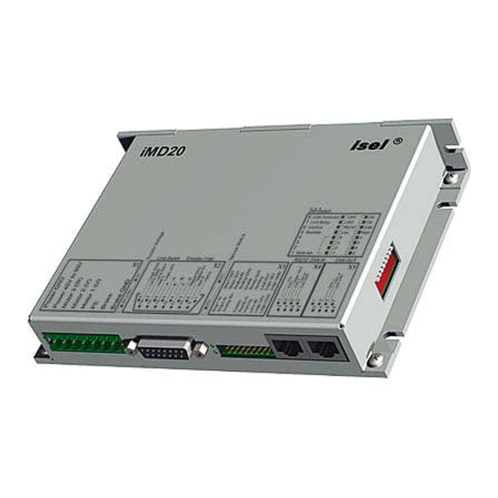
AC servo positioning module with CanOpen interface
Brand:
Isel
| Category:
Control Unit
| Size: 2 MB
Table of Contents
Table of Contents
3
Overview
7
Features of the Drive Module
7
Scope of Application
7
Safety Notes for Electrical Drives and Controllers
8
Used Symbols
8
General Notes
8
Danger Resulting from Misuse
9
General Safety Notes
10
Safety Notes for Assembly and Maintenance
11
Protection against Contact with Electrical Parts
12
Protection against Electrical Shock by Means of Protective Extra-Low Voltage (PELV)
13
Protection against Dangerous Movements
13
Protection against Contact with Hot Parts
14
Protection During Handling and Assembly
14
Notes on Safe and EMC-Compliant Installation
15
Definition and Terms
15
General Information on EMC
16
EMC-Compliant Cabling
16
Description of the Drive Module
18
Settings and Status Display
18
DIP Switch
18
Modes of Operation
18
Leds IMD20
19
Leds IMD40
20
Hardware Description IMD20
21
Connectors
21
Frame Connector X1 - Connection of the Operating Voltage 40V-95V, Motor and Brake
21
Frame Connector X2 - 15-Pin Sub-D - Connection of the Encoder, Hall Sensors and Limit Switch
22
Frame Connector X3 - 20 Pin - System Connection
22
Frame Connector X4 - RJ45 - RS-232 and CAN in
23
Frame Connector X5 - RJ45 - CAN out
23
Jumper Settings
23
Wiring of the Inputs and Outputs
23
Digital Inputs Limit Switch, Enable
23
Digital Output Ready
24
Digital Output Homing
24
Digital Output Brake
24
Digital Output Limit Switch Chain
25
Analogue Input
25
Encoder Connections
25
Can
26
Hardware Description IMD40
27
Connectors
27
Frame Connector X1 - Connection of the Operating Voltage AC 220V, Motor and Brake
27
Frame Connector X2 -Connection of Operating Voltage 24V, Temperature and Brake
28
Frame Connector X3 - 15-Pin Sub-D - Connection Encoder, Hall Sensors, Limit Switch
28
Frame Connector X4 - 20-Pin - System Connection
29
Frame Connector X5 - RJ45 - RS-232 und CAN in
29
Frame Connector X6 - RJ45 - CAN out
29
Frame Connector X7 - Brake Resistor
30
Jumper Settings
30
Wiring of the Inputs and Outputs
31
Digital Inputs Limit Switches, Reference Switch, Enable
31
Digital Output Ready
31
Digital Output Homing
31
Digital Output Brake
31
Digital Output Limit Switch Chain
32
Analogue Input
32
Encoder Connections
33
Can
33
Data Transfer
34
Commissioning
36
Overview
36
Particularities as Regards the Commissioning of a Gantry Axis
36
Examples for the Motion Control
36
Example 1
36
Example 2
37
Example 3
39
Fault States
40
Acsetup Programme
41
Menus
41
Commands of the File Menu
41
The New Command (File Menu)
41
The Open Command (File Menu)
41
The Save Command (File Menu)
41
The Save as Command (File Menu)
41
The 1, 2, 3, 4 Commands (File Menu)
41
The Exit Command (File Menu)
41
Commands of the Connection Menu
42
The Online Mode On/Off Command
42
The Active Connection / CAN Command
42
The Active Connection / RS232 Command
42
The RS232 Settings Command
42
The CAN Settings Command
42
Commands of the Commissioning Menu
43
The Step-By-Step Commissioning Command
43
The Random Order Command
43
The Reset Command
43
Commands of the Settings Menu
43
The Object Directory Command
43
Commands of the Extra Menu
43
The Extended Functions Command
43
Password
43
The Firmware Update / Normal Command
44
The Firmware Update / Via Bootstrap Loader Command
44
Commands of the View Menu
45
The Tool Bar Command
45
The Status Bar Command
45
The Serial Interface Command
45
The CAN Monitor Command
45
The Drive Status Command
45
The Language Command
45
Commands of the ? Menu
45
The Help Topics Command
45
The Info Command
45
Programme User Interface
46
Tool Bar
46
Status Bar
46
Drive Status
47
Monitor Window for Serial Interface
47
Monitor Window for CAN Communication
48
Programme Functions
49
Create a Data Connection
49
Offline Operation
49
Online Operation
49
Choose Active Connection
49
32 Settings
49
CAN Settings
50
Commissioning / Adjustment of Parameters
51
Step-By-Step Commissioning
51
Random Order
51
Connection Dialogue Box
53
Mode of Operation Dialogue Box
54
Offset Calibration Dialogue Box
55
Analogue Input Dialogue Box
56
Brake Dialogue Box
57
Current Controller Dialogue Box
58
Encoder Dialogue Box
60
Motor and Transmission Dialogue Box
61
Velocity Controller Dialogue Box
63
Direction Dialogue Box
66
Acceleration Dialogue Box
67
Velocity Dialogue Box
68
Position Controller Dialogue Box
69
Can Interpolation Dialogue Box
72
Inputs Dialogue Box
74
Reference Run Dialogue Box
75
Object Directory Dialogue Box
76
Firmware Update
78
Canopen Protocol
79
Overview
79
Sdo
81
Pdo
83
Mapping
83
Types of Transfer
84
Sync
85
Emcy
86
Network Management - NMT
86
Status Diagram
87
Boot-Up Object
88
Monitoring - Guarding
88
Object Directory
90
Communications Parameter
90
General Communications Parameters
90
PDO / Mapping Parameters
94
Device Profile Parameters
99
Device Control
99
Mode of Operation
101
Current Control
102
Profile Position Mode - Position Control with Ramp Profile
105
Interpolated Position Mode - Position Control with Interpolation
107
Homing Mode - Reference Run
109
Moving the Axis out of a Limit Switch
111
Factor Group - Conversion Factors
111
General Parameters
113
Manufacturer-Specific Parameters
120
EDS / DCF Files
128
Appendix
129
Connection of Motionking EC Motor to the IMD20, IMD40
129
Encoder Connection
129
Motor Connection
130
IMD20 Basis Connection
131
IMD20 System Connection
132
Glossary
133
Index
134
Advertisement
Advertisement
Related Products
Isel iPC25-F
Isel ICP 4030
Isel ICP 3020
Isel ICP 2015
Isel IMD1
Isel IMD40
Isel iPC15
Isel iMC Series
Isel iMC-B
Isel iMC-V
Isel Categories
Controller
Control Unit
Industrial Equipment
Scooter
Control Systems
More Isel Manuals
Login
Sign In
OR
Sign in with Facebook
Sign in with Google
Upload manual
Upload from disk
Upload from URL