Sign In
Upload
Manuals
Brands
IS5 COMMUNICATIONS Manuals
Switch
IEC61850
IS5 COMMUNICATIONS IEC61850 Switch Manuals
Manuals and User Guides for IS5 COMMUNICATIONS IEC61850 Switch. We have
1
IS5 COMMUNICATIONS IEC61850 Switch manual available for free PDF download: User Manual
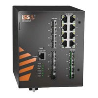
IS5 COMMUNICATIONS IEC61850 User Manual (190 pages)
Intelligent 20 Port Managed Gigabit Ethernet Switch IEC61850 and IEEE1613 Compliant
Brand:
IS5 COMMUNICATIONS
| Category:
Switch
| Size: 6 MB
Table of Contents
Table of Contents
3
FCC Statement and Cautions
9
Federal Communications Commission Radio Frequency Interference Statement
9
Caution: LASER
9
Caution: Service
9
Caution: Physical Access
9
Getting Started
10
About Ies22Gf
10
References
11
Acronyms
11
Software Features
15
Hardware Specifications
15
Hardware Overview
16
Front Panel
16
Front Panel LED
17
Bottom View of Panel
17
Rear Panel
19
Side Panel
19
Figure 1 - Rear Panel
19
Figure 2 - Side Panel
19
Hardware Installation
20
Installing the Switch on DIN-Rail
20
Mounting on DIN-Rail
20
Figure 3 - DIN-Rail Bracket
20
Figure 4 - Switch Mounted on DIN-Rail
20
Wall Mount Installation
21
Mounting Ies22Gf on a Wall or Panel
21
Figure 5 - Brackets Mounted on Side of Switch
21
Figure 6 - Brackets Mounted on Back of Switch
21
Connection
22
Ethernet Cables
22
Pin Assignments
22
Table 1 - Port Numbering
22
Table 2 - 10/100 Base-T(X) Line Pin Assignments
22
Table 3 - 1000 Base-T Line Pin Assignments
22
Sfp
23
Figure 7 - Sfps
23
Table 4 - 10/100 Base-T(X) MDI/MDI- X Pin Assignments
23
Table 5 - 1000 Base-T MDI/MDI- X Pin Assignments
23
Console Cable
24
Figure 8 - Console Cable Connection
24
Table 6 - Signals and Pinouts from Console Port RJ-45 to DB-9 Serial Port Adapter
24
Redundancy Overview
25
Stp/Rstp/Mstp
25
Stp/Rstp
25
Mstp
25
Fast Recovery
25
Web Management
26
Figure 9 - Switch's IP Address Screen
26
Figure 10 - Login Screen
26
Figure 11 - Main Interface or System Information Tab
27
Basic Setting
28
Basic Setting (System Information Configuration)
28
Figure 12 - System Information Configuration
28
Banner
29
Admin Password
29
Figure 13 - System Banner Configuration
29
Figure 14 - System Password
29
Guest Password
30
Authentication Method
30
Figure 15 - Guest Password Configuration
30
Figure 16 - Authentication Method Configuration
30
Auto Logout
31
IP Setting
31
Figure 17 - Auto Logout Configuration
31
Figure 18 - IP Configuration
31
Ipv6 Setting
32
Figure 19 - Ipv6 Configuration
32
SNTP Configuration (Only for SNTP Version)
33
Figure 20 - SNTP Configuration
33
NTP Configuration (Only for NTP Version)
34
Figure 21 - NTP Configuration
34
Daylight Saving Time
35
Figure 22 - Time Zone Configuration
35
Switch Time Configuration
36
Https
36
Figure 23 - Switch Time Configuration
36
Figure 24 - HTTPS Configuration
36
Ssh
37
Telnet
37
Figure 25 - SSH Configuration
37
Figure 26 - Telnet Configuration
37
Lldp
38
Figure 27 - LLDP Configuration
38
Figure 28 - LLDP Neighbor Information
39
Figure 29 - LLDP Global Counters
40
Modbus TCP
41
Backup
41
Figure 30 - MODBUS Configuration
41
Restore
42
Firmware Update
42
Figure 31 - Configuration Save
42
Figure 32 - Configuration Upload
42
Figure 33 - Software Upload
43
DHCP Server/Relay
44
Setting
44
Figure 34 - DHCP Server Configuration
44
DHCP Dynamic Client List
45
DHCP Static Client List
45
Figure 35 - DHCP Dynamic Client List
45
Figure 36 - DHCP Static Client List
45
DHCP Relay Agent
46
Figure 37 - DHCP Relay Configuration
46
Figure 38 - DHCP Relay Statistics
47
Figure 39 - Client Statistics
47
Port Setting
48
Port Control
48
Figure 40 - Port Configuration
48
Port Trunk
50
Figure 41 - Aggregation Mode Configuration
50
Figure 42 - Aggregation Group Configuration
50
Figure 43 - LACP Port Configuration
51
Figure 44 - LACP System Status
52
Figure 45 - LACP Status
53
Figure 46 - LACP Statistics
54
Loop Protection
55
Figure 47 - Loop Protection
55
Figure 48 - Port Configuration
55
Redundancy
56
Iring
56
Figure 49 - Iring Configuration
56
Ichain
57
Ibridge
57
Figure 50 - Ichain Configuration
57
Figure 51 - Ibridge
57
Rstp
58
Figure 52 - RSTP Bridge Setting Interface
58
Figure 53 - RSTP Port Setting
59
Figure 54 - RSTP Bridge Status
60
Figure 55 - RSTP Port Status
61
Mstp
62
Figure 56 - STP Bridge Configuration
62
Figure 57 - MSTI Configuration
63
Figure 58 - MSTI Configuration
64
Figure 59 - STP MSTI Port Configuration
65
Figure 60 - MSTI Port Configuration
67
Figure 61 - STP Bridges
68
Figure 62 - STP Port Status
68
Figure 63 - STP Statistics
69
Mrp
70
Fast Recovery
70
Figure 64 - MRP
70
Figure 65 - Fast Recovery
71
Dual Port Recovery
72
Figure 66 - Dual Port Recovery
73
Vlan
74
VLAN Membership
74
Figure 67 - VLAN Membership Configuration
74
Ports Configuration
75
Figure 68 - VLAN Port Configuration
75
Figure 69 - VLAN Membership Configuration
80
Figure 70 - VLAN Port Configuration
80
Figure 71 - VLAN Membership Configuration
81
Figure 72 - VLAN Port Configuration
81
Figure 73 - VLAN Membership Configuration
82
Figure 74 - VLAN Port Configuration
82
Figure 75 - VLAN Membership Configuration
83
Figure 76 - VLAN Port Configuration
83
Figure 77 - IP Configuration
83
Private VLAN
84
Figure 78 - Private VLAN Membership Configuration
84
Figure 79 - Port Isolation Configuration
85
Snmp
86
SNMP System Configurations
86
Figure 80 - SNMP System Configuration
86
Figure 81 - SNMP Trap Configuration
87
SNMP Community Configurations
88
Figure 82 - Snmpv3 Community Configuration
88
SNMP User Configurations
89
Figure 83 - Snmpv3 User Configuration
89
SNMP Group Configurations
91
SNMP View Configurations
91
Figure 84 - Snmpv3 Group Configuration
91
Figure 85 - Snmpv3 View Configuration
91
SNMP Access Configurations
92
Figure 86 - Snmpv3 Access Configuration
92
Traffic Prioritization
94
Storm Control
94
Port Classification
94
Figure 87 - Qos Port Storm Control
94
Figure 88 - Qos Ingress Port Classification
95
Port Tag Remarking
96
Figure 89 - Qos Egress Port Tag Remarking
97
Port DSCP
98
Figure 90 - Qos Port DSCP Configuration
98
Port Policing
99
Figure 91 - Qos Ingress Port Policers
99
Queue Policing
100
Port Schedulers
100
Figure 92 - Qos Ingress Queue Policers
100
Figure 93 - Qos Egress Port Policers
100
Port Shaping
101
Figure 94 - Qos Egress Port Shapers
101
Figure 95 - Qos Ingress Port Scheduler and Shapers Port 1- Strict Priority
101
Figure 96 - Qos Egress Port Scheduler and Shapers Port 1 - Scheduler Mode Weighted
102
DSCP-Based Qos
104
Figure 97 - Qos DSCP-Based Qos Ingress Classification
104
DSCP Translation
105
Figure 98 - DSCP Translation
105
DSCP Classification
106
Figure 99 - DSCP Classification
106
Qos Control List
107
Figure 100 - Qos Control List Configuration
107
Qos Statistics
109
Figure 101 - Qos Statistics
109
Figure 102 - Detailed Port Statistics Port 7
110
QCL Status
111
Figure 103 - Qos Control List Status
111
Multicast
113
IGMP Snooping Basic Configuration
113
Figure 104 - IGMP Snooping Configuration
113
IGMP Snooping VLAN Configurations
114
Figure 105 - IGMP Snooping VLAN Configuration
114
IGMP Snooping Status
115
Figure 106 - IGMP Snooping Status
115
IGMP Snooping Group Information
116
Figure 107 - IGMP Snooping Group Information
116
Security
117
Remote Control Security Configuration
117
Device Binding
117
Figure 108 - Remote Control Security Configuration
117
Figure 109 - Device Binding
117
Figure 110 - Alias IP Address
119
Figure 111 - Alive Check
119
Figure 112 - Ddos Prevention
120
Figure 113 - Device Description
121
Figure 114 - Steam Check
122
Acl
123
Figure 115 - ACL Ports Configuration
123
Figure 116 - ACL Rate Limiter Configuration
124
Figure 117 - ACL Control List Configuration
125
Figure 118 - Default ACE Configuration
125
Figure 119 - ACE Configuration
126
Figure 120 - MAC Parameters
127
Figure 121 - VLAN Parameters (Default Values or with Filter "Specific")
127
Figure 122 - IP Parameters
128
Figure 123 - ARP Parameters
130
Figure 124 - ICMP Parameters
132
Figure 125 - TCP / UDP Parameters
133
Figure 126 - Ethernet Type Parameters
135
Figure 127 - ACL Status
136
Aaa
137
Figure 128 - Common Server Configuration
137
Figure 129 - RADIUS Authentication Server Configuration
138
Figure 130 - RADIUS Accounting Server Configuration
138
Figure 131 - TACACS+ Authentication Server Configuration
139
Figure 132 - Radius Authentication Server Status Configuration
139
Figure 133 - Radius Accounting Server Status Configuration
140
Figure 134 - Radius Authentication Statistics for Server #1
141
Figure 135 - Radius Accounting Statistics for Server #1
143
NAS (802.1X)
146
Figure 136 - Network Access Server Configuration
147
Figure 137 - Network Access Server Port Configuration
149
Figure 138 - Network Access Server Switch Status
151
Figure 139 - NAT Statistics Admin State Force Authorized
152
Figure 140 - EAPOL Counters Admin State Force Authorized
153
Figure 141 - NAT Statistics Admin MAC-Based Auth
154
Figure 142 - Last Supplicant/ Client Info Admin State MAC-Based Auth
156
Figure 143 - Last Supplicant/ Client Info Admin State 802.1X-Based
156
Figure 144 - Selected Counters / Attached Clients
157
Warning
158
Fault Alarm
158
System Warning
158
Figure 145 - Fault Alarm
158
Figure 146 - System Log Configuration
158
Figure 147 - SMTP Settings
159
Figure 148 - System Warning - Event Selection
160
Monitor and Diagnostic
161
MAC Table
161
Figure 149 - MAC Address Table Configuration
161
Figure 150 - MAC Address Table
163
Port Statistic
164
Figure 151 - Port Statistics Overview
164
Figure 152 - Detailed Post Statistics
165
Port Monitoring
166
Figure 153 - Mirror Configuration
166
System Log Information
167
Veriphy Cable Diagnostics
167
Figure 154 - System Log Information
167
Figure 155 - Veriphy Cable Diagnostics
168
SFP Monitor
169
Ping
169
Figure 156 - SFP Monitor
169
Figure 157 - ICMP Ping
169
Ping6
170
Factory Defaults
170
Figure 158 - Icmpv6 Ping
170
System Reboot
171
Figure 159 - Factory Defaults
171
Figure 160 - System Reboot - Restart Device
171
CLI Management
172
Command Line Interface Setup
172
CLI Management by RS-232 Serial Console (115200, 8, None, 1, None)
172
Figure 161 - Tera Term VT, Setup Menu
172
Figure 162 - Tera Term VT, Serial Port Setup
172
Figure 163 - Ies22Gf Command Line Interface - Tera Term VT
173
CLI Management by Telnet
174
Figure 164 - Telnet Command Prompt
174
Figure 165 - Ies22Gf Command Line Interface - Telnet
174
Command Groups
175
Figure 166 - Command Groups Printout
175
Appendix A: Ies22Gf Modbus Information
190
Advertisement
Advertisement
Related Products
IS5 COMMUNICATIONS iES28TG
IS5 COMMUNICATIONS iES28GF
IS5 COMMUNICATIONS iES22GF
IS5 COMMUNICATIONS iES26GF
IS5 COMMUNICATIONS iES20G Series
IS5 COMMUNICATIONS iES18G Series
IS5 COMMUNICATIONS iES6 Series
IS5 COMMUNICATIONS iES6-S Series
IS5 COMMUNICATIONS IES12G
IS5 COMMUNICATIONS iTS12GP
IS5 COMMUNICATIONS Categories
Switch
Media Converter
Network Router
Network Hardware
Firewall
More IS5 COMMUNICATIONS Manuals
Login
Sign In
OR
Sign in with Facebook
Sign in with Google
Upload manual
Upload from disk
Upload from URL