Sign In
Upload
Manuals
Brands
INVT Manuals
Media Converter
GD350-011G/015P-4-UL
INVT GD350-011G/015P-4-UL Frequency Drive Manuals
Manuals and User Guides for INVT GD350-011G/015P-4-UL Frequency Drive. We have
2
INVT GD350-011G/015P-4-UL Frequency Drive manuals available for free PDF download: Operation Manual
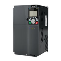
INVT GD350-011G/015P-4-UL Operation Manual (432 pages)
High-performance Multifunction VFD
Brand:
INVT
| Category:
Media Converter
| Size: 32 MB
Table of Contents
Table of Contents
4
Safety Precautions
11
What this Chapter Contains
11
Safety Definition
11
Warning Symbols
11
Safety Guidelines
12
Delivery and Installation
12
Commissioning and Running
13
Maintenance and Component Replacement
14
What to Do after Scrapping
14
Quick Start
15
What this Chapter Contains
15
Unpack Inspection
15
Application Confirmation
15
Environment Confirmation
15
Installation Confirmation
16
Basic Commissioning
16
Safety Standard Related Data
17
Product Overview
18
What this Chapter Contains
18
Basic Principle
18
Product Specifications
19
Product Nameplate
22
Model Code
22
Product Ratings
23
Ac 3Ph 200V-240V
23
Ac 3Ph 380V-480V
24
Ac 3Ph 520V-600V
25
Structure Diagram
26
Installation Guidelines
27
What this Chapter Contains
27
Mechanical Installation
27
Installation Environment
27
Installation Direction
28
Installation Mode
29
Single-Unit Installation
29
Multiple-Unit Installation
30
Vertical Installation
31
Tilted Installation
32
Standard Wiring of Main Circuit
33
Wiring Diagram of Main Circuit
33
Main Circuit Terminal Diagram
34
Wiring Process of the Main Circuit Terminals
39
Standard Wiring of Control Circuit
40
Wiring Diagram of Basic Control Circuit
40
Input/Output Signal Connection Diagram
42
Wiring Protection
43
Protecting the VFD and Input Power Cable in Short Circuit
43
Protecting the Motor and Motor Cable in Short Circuit
44
Protecting the Motor and Preventing Thermal Overload
44
Bypass Connection
44
Basic Operation Instructions
45
What this Chapter Contains
45
Keypad Introduction
45
Keypad Display
49
Displaying Stopped-State Parameters
49
Displaying Running-State Parameters
50
Displaying Fault Information
50
Operating the VFD through the Keypad
51
Entering/Exiting Menus
51
Editing a Parameter List
56
Adding Parameters to the Parameter List Displayed in Stopped/Running State
57
Adding Parameters to the User Defined Parameter List
58
Editing User Defined Parameters
58
Editing Parameters in Parameter Groups
59
Monitoring States
59
Autotuning Motor Parameters
60
Backing up Parameters
60
System Settings
61
Power-On Setup Wizard
61
Basic Operation Instruction
63
What this Section Contains
63
Common Commissioning Procedure
63
Vector Control
67
SVPWM Control Mode
72
Torque Control
81
Motor Parameter
85
Start/Stop Control
91
Frequency Setting
97
Analog Input
101
Analog Output
104
Digital Input
109
Digital Output
118
Simple PLC
124
Multi-Step Speed Running
126
PID Control
128
Run at Wobbling Frequency
133
Local Encoder Input
135
Commissioning Procedures for Closed-Loop Control, Position Control and Spindle Positioning
136
Fault Handling
141
Tension Control Solutions
146
Function Parameter List
151
What this Chapter Contains
151
P00 Group-Basic Functions
152
P01 Group-Start/Stop Control
156
P02 Group-Parameters of Motor 1
162
P03 Group-Vector Control of Motor 1
166
P04 Group-V/F Control
173
P05 Group-Input Terminals
181
P06 Group-Output Terminals
189
P07 Group-HMI
195
P08 Group-Enhanced Functions
201
P09 Group-PID Control
209
P10 Group-Simple PLC and Multi-Step Speed Control
214
P11 Group-Protection Parameters
217
P12 Group-Parameters of Motor 2
225
P13 Group-Control Parameters of Synchronous Motor
229
P14 Group-Serial Communication Function
230
P15 Group-Functions of Communication Expansion Card 1
235
P16 Group-Functions of Communication Expansion Card 2
238
P17 Group-Status Viewing
243
P18 Group-Closed-Loop Control State Check
248
P19 Group-Expansion Card State Check
251
P20 Group-Encoder of Motor 1
253
P21 Group-Position Control
257
P22 Group-Spindle Positioning
263
P23 Group-Vector Control of Motor 2
266
P24 Group-Encoder of Motor 2
268
P25 Group-Extension I/O Card Input Functions
271
P26 Group-Output Functions of Expansion I/O Card
275
P27 Group-Programmable Expansion Card Functions
278
P28 Group-Master/Slave Control Functions
281
P90 Group-Tension Control in Speed Mode
284
P91 Group-Tension Control in Torque Mode
288
P92 Group-Customized Tension Control Functions
291
P93 Group-Tension Control Status Viewing
292
Troubleshooting
295
What this Chapter Contains
295
Indications of Alarms and Faults
295
Fault Reset
295
Fault History
295
VFD Faults and Solutions
295
Details of Faults and Solutions
295
Other State
303
Analysis on Common Faults
304
Motor Fails to Work
304
Motor Vibrates
305
Overvoltage
306
Undervoltage
306
Unusual Heating of Motor
307
VFD Overheating
308
Motor Stalls During ACC
309
Overcurrent
310
Countermeasures on Common Interference
311
Interference on Meter Switches and Sensors
311
Interference on Communication
312
Failure to Stop and Indicator Shimmering Due to Motor Cable Coupling
313
Leakage Current and Interference on RCD
313
Live Device Chassis
314
Maintenance
315
What this Chapter Contains
315
Periodical Inspection
315
Cooling Fan
317
Capacitor
318
Capacitor Reforming
318
Electrolytic Capacitor Replacement
319
Power Cable
320
Communication Protocol
321
What this Chapter Contains
321
Modbus Protocol Introduction
321
Application of Modbus
321
Rs485
321
RTU Mode
324
RTU Command Code and Communication Data
327
Command Code: 03H, Reading N Words (Continuously Reading a Maximum of 16 Words)
327
Command Code: 06H, Writing a Word
329
Command Code: 08H, Diagnosis
330
Command Code: 10H, Continuous Writing
330
Data Address Definition
331
Fieldbus Scale
335
Error Message Response
336
Read/Write Operation Example
338
Common Communication Faults
343
Appendix A Expansion Cards
344
Model Definition
344
Dimensions and Installation
352
Wiring
355
IO Expansion Card (EC-IO501-00)
355
IO Expansion Card 2 (EC-IO502-00)
357
Programmable Expansion Card (EC-PC502-00)
360
Communication Cards
362
Bluetooth Communication Card (EC-TX501) and WIFI Communication Card (EC-TX502)
362
PROFIBUS-DP Communication Card (EC-TX503)
364
Ethernet Communication Card (EC-TX504)
366
Canopen Communication Card (EC-TX505) and CAN Master/Slave Control
367
Communication Card (EC-TX511)
367
PROFINET Communication Card (EC-TX509)
368
Ethernet/Ip Communication Card (EC-TX510) and Modbus TCP Communication Card (EC-TX515)
370
PG Expansion Card Function Description
372
Sin/Cos PG Card (EC
372
UVW Incremental PG Card (EC
375
Resolver PG Card (EC
377
Multifunction Incremental PG Card (EC
379
Incremental PG Card (EC
383
Simplified Incremental PG Card (EC
386
Simplified Incremental PG Card (EC
387
GPRS Card (EC-IC501-2)
391
Appendix B Technical Data
392
What this Chapter Contains
392
Derated Application
392
Capacity
392
Derating
392
Grid Specifications
394
Motor Connection Data
394
EMC Compatibility and Motor Cable Length
394
Application Standards
394
CE Marking
395
UL and CUL Marking
395
EMC Compliance Declaration
395
EMC Regulations
395
VFD Category C2
396
VFD Category C3
396
Appendix C Dimension Drawings
397
What this Chapter Contains
397
Keypad Structure
397
Structure Diagram
397
Keypad Installation Bracket
397
VFD Structure
398
Dimensions of Vfds of AC 3PH 200V-240V and 380V-480V
398
Wall Installation Dimensions
398
Flange Installation Dimensions
401
Floor Installation Dimensions
403
Dimensions of Vfds of AC 3PH 520V-600V
404
Wall Installation Dimensions
404
Flange Installation Dimensions
405
Appendix D Optional Peripheral Accessories
407
What this Chapter Contains
407
Wiring of Peripheral Accessories
407
Power Supply
408
Cables
408
Power Cables
408
Control Cables
409
Cable Arrangement
413
Insulation Inspection
413
Breaker and Electromagnetic Contactor
414
Reactors
416
Filters
419
Filter Model Description
419
Filters
420
Brake System
421
Braking Component Selection
421
Braking Resistor Cable Selection
424
Braking Resistor Installation
424
Appendix E STO Function Description
426
STO Function Logic Table
426
STO Channel Delay Description
426
STO Function Installation Checklist
427
Appendix F Acronyms and Abbreviations
428
Appendix G Energy Efficiency Data
429
Appendix H Further Information
431
Product and Service Queries
431
Feedback on INVT VFD Manuals
431
Documents on the Internet
431
Advertisement
INVT GD350-011G/015P-4-UL Operation Manual (366 pages)
High-performance Multi-function VFD
Brand:
INVT
| Category:
DC Drives
| Size: 28 MB
Table of Contents
Table of Contents
4
Chapter 1 Safety Precautions
7
What this Chapter Contains
7
Safety Definition
7
Warning Symbols
7
Safety Guidelines
8
Chapter 2 Quick Start
11
What this Chapter Contains
11
Unpack Inspection
11
Application Confirmation
11
Environment Confirmation
11
Installation Confirmation
12
Basic Commissioning
12
Chapter 3 Product Overview
14
What this Chapter Contains
14
Basic Principle
14
Product Specification
15
Product Nameplate
18
Model Code
18
Rated Specifications
19
Structure Diagram
21
Chapter 4 Installation Guidelines
22
What this Chapter Contains
22
Mechanical Installation
22
Standard Wiring of Main Circuit
28
Standard Wiring of Control Circuit
35
Wiring Protection
38
Chapter 5 Basic Operation Instructions
40
What this Chapter Contains
40
Keypad Introduction
40
Keypad Display
44
Keypad Operation
46
Basic Operation Instruction
59
Chapter 6 Function Parameter List
137
What this Chapter Contains
137
Function Parameter List
137
Chapter 7 Troubleshooting
244
What this Chapter Contains
244
Indications of Alarms and Faults
244
Fault Reset
244
Fault History
244
VFD Faults and Solutions
244
Analysis on Common Faults
253
Countermeasures on Common Interference
260
Chapter 8 Maintenance and Hardware Fault Diagnosis
264
What this Chapter Contains
264
Periodical Inspection
264
Cooling Fan
266
Capacitor
267
Power Cable
269
Chapter 9 Communication Protocol
270
What this Chapter Contains
270
Modbus Protocol Introduction
270
Application of Modbus
270
RTU Command Code and Communication Data
276
Common Communication Faults
291
Appendix A Extension Cards
293
Model Definition
293
Dimensions and Installation
299
Wiring
302
IO Extension Card (EC-IO501-00) Function Description
302
Programmable Extension Card (EC-PC501-00) Function Description
304
Communication Card Function Description
306
PG Extension Card Function Description
314
Appendix B Technical Data
330
What this Chapter Contains
330
Derated Application
330
Grid Specifications
332
Motor Connection Data
332
Application Standards
333
EMC Regulations
333
Appendix C Dimension Drawings
335
What this Chapter Contains
335
Keypad Structure
335
VFD Structure
336
Dimensions of Vfds of AC 3PH 200V-240V and 380V-480V
336
Dimensions of Vfds of AC 3PH 520V-600V
342
Appendix D Optional Peripheral Accessories
344
What this Chapter Contains
344
Wiring of Peripheral Accessories
344
Power Supply
345
Cables
345
Breaker and Electromagnetic Contactor
350
Reactors
352
Filters
354
Brake System
358
Appendix E STO Function Description
362
STO Function Logic Table
362
STO Channel Delay Description
362
STO Function Installation Checklist
363
Appendix F Acronyms and Abbreviations
364
Appendix G Further Information
365
Product and Service Queries
365
Feedback on INVT VFD Manuals
365
Documents on the Internet
365
Advertisement
Related Products
INVT GD350-011G/015P-45-AS
INVT GD350-011G-2-UL
INVT GD350-011G-6-UL
INVT GD350-018G/022P-45-AS
INVT GD350-015G-2-UL
INVT GD350-018G-2-UL
INVT GD350-015G/018P-4-UL
INVT GD350-018G/022P-4-UL
INVT GD350-015G-6-UL
INVT GD350-018G-6-UL
INVT Categories
Inverter
DC Drives
Servo Drives
Controller
UPS
More INVT Manuals
Login
Sign In
OR
Sign in with Facebook
Sign in with Google
Upload manual
Upload from disk
Upload from URL