Sign In
Upload
Manuals
Brands
INVT Manuals
Control Systems
EC160
INVT EC160 Manuals
Manuals and User Guides for INVT EC160. We have
1
INVT EC160 manual available for free PDF download: Operation Manual
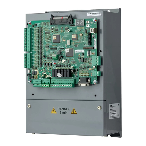
INVT EC160 Operation Manual (228 pages)
Elevator Intelligent Integrated Machine
Brand:
INVT
| Category:
Control Systems
| Size: 3 MB
Table of Contents
Main Features
2
Table of Contents
3
Hardware Configuration
8
Chapter 1 EC160 Configuration
8
Standard Functions of Software
9
Optional Functions of Software
17
Safety Marks
19
Reader Group
19
Warning Marks
19
Chapter 2 Safety Precautions and Notices
19
Safety Precautions
20
Unpacking Inspection
20
Disassembly and Assembly
20
Connection Precautions
20
Running Precautions
21
Maintenance and Inspection Precautions
22
Other Precautions
22
Model Description
23
Name Plate
23
Power Selection
23
Chapter 3 Product Overview
23
Technical Specifications
24
Delivery Confirmation
26
Digitron Displaying and Operation Instruction
26
Running Environment
27
Temperature&Humidity
27
Altitude
27
Other Environmental Requirements
27
Chapter 4 Installation and Wiring
28
Dimensions
29
Terminals Instruction
30
Terminals of Main Circuit
31
Terminal Arrangement
31
Function Instruction
31
Specification of the Main Circuit Leads
32
Configuration Precautions
32
Connection of RBU Series Energy Feedback Unit
33
Connection of Braking Circuit of Intelligent Integrated Machine in Main Circuit
33
Connection of PE Terminal
34
Connection Diagram of Energy Feedback Unit
34
Terminals of Control Circuit
34
Definition of Terminals
34
Specification of Relay Digital Output Signal
38
Encoder Wiring of Asynchronous Master
38
Encoder Wiring of Synchronous Master
38
System Installation and Configuration
39
Electrical Installation of Hoistway
39
Installation Position of Hoistway Switch
40
Connection Precautions of Peripheral Devices
43
CAN Communication Configuration
43
Breaker
43
AC Reactor at the Input Side
43
Installation Guideline to EMC Compliance
45
General Knowledge of EMC
45
EMC Features of Inverter
45
EMC Installation Guideline
46
Noise Control
46
Site Wiring
46
Grounding
47
Leakage Current
47
EMC Filter
47
Installation Specification
47
Main Controlling Interface
48
Password Setting
48
System Autotuning
48
Chapter 5 Debugging Tools
48
Instruction
48
Fault Record
48
Parameters Setting
48
Data Management
48
Connection Method
49
Keys and LED Indicator
49
Key Definition
49
Interface of the Manual Controller and EC160
49
Operation Procedure Flowchart
50
Manual Controller and LED Indicator
50
Simple Manual Controller
51
Introduction
51
Key Instruction
51
LED Indicator Instruction
52
Comparison Table of Digitron Word
52
Operation Procedure Flowchart
54
Monitoring Instruction
54
Corresponding List of Function Parameters
56
Original Debugging Interface
80
System Monitoring
80
Calling State
80
Chapter 6 Function Parameters
80
Running State
81
System Monitoring---Drive State
81
System Monitoring---Random Running
81
System Monitoring---Main Controller
82
Fault History Record
83
System Monitoring---Car Controller
83
Language Selection
84
Parameters Setting Inquiry
84
Parameters Setting---Master Drive Control
85
Rated Speed of the Elevator
85
Speed Control Mode
85
Carrier Frequency Setting
86
Max. Output Frequency
86
Max. Speed of the Elevator
86
Running Direction
86
Parameters Setting---Speed and Deceleration Distance
87
Parameters Diagram of S Curve
88
Inspection Speed
89
Peristaltic Landing Speed
89
Pre-Opening Speed Threshold
89
Zero-Speed Threshold
89
Parameters Setting---Motor Parameters
90
Motor Type Selection
91
Resistance of the Rotor
91
Resistance of the Stator
91
Parameters Setting---Encoder Parameters
92
Encoder Direction
93
Encoder Resolution
93
Encoder Type Selection
93
Parameters Setting---Running Comfortability
95
Pulse Counting Direction
95
SIN/COS Encoder Phase Line
95
Static Identification Current
95
Parameters of Speed Loop PI
98
ACR Switching
99
Weighing Input Selection
101
Parameters Setting---Elevator Protection Parameters
102
Parameters Setting---Communication Setting
105
Communication Response Enabling
106
Data Format
106
Local Communication Address
106
Communication Response Delay
107
Communication Timeout Fault
107
Parameters Setting
108
Parameters Setting---Floor Setting
109
Parameters Setting---Floor Displaying Setting
110
Parameters Setting---Logic Setting of I/O Control Board
114
Parameters Setting
117
Parameters Setting
119
Parameters Setting---Rear Door Stopping Floor
122
Parameters Setting---Front/Rear Door Stopping Floor
123
Parameters Setting---Parallel and Group Control Setting
124
Parameters Setting---Time Setting
126
Free Energy-Saving Delay
127
Open Delay
127
Return to the Home Floor Delay
127
Direction Cancel Delay
128
Fire Running Delay
128
Inspection Stopping Delay
128
Starting Shake Prevention Delay
128
Arrival Gong Delay
129
Thermal Protection Reset Delay
129
Entire Running Protection Time
130
Fast Arrival Opening Delay
130
Keeping Time of Opening Delay
130
Beam Keeping Failure Time
131
Parameters Setting---Function Setting
131
Hand Door Enabling
132
High/Low Voltage Detection
132
Closing Output Delay
133
Fire Safety Mode
133
Test Mode
137
Parameters Setting
143
Parameters Setting
144
Parameters Setting
146
Data Management
147
Password Setting
147
System Autotuning
147
System Information
148
Electrical Assembly, Inspection and Confirmation
149
Inspection before Power on
149
Machinery Assembly, Inspection and Confirmation
149
Chapter 7 Running at Slow Speed
149
Check the Grounding
150
Inspection of the Encoder Assembly
150
Inspection after Power on
151
Static Self-Tuning of the Synchronous Motor
152
Rotating Autotuning of the Motor
156
Inspection Running
159
Inspection and Confirmation of the Electrical Assembly
160
Power on and Check
160
Chapter 8 Debugging at Fast Speed
160
Inspection of the Beam
161
Connection Inspection of the Leveling Sensor
161
Parameter Check
162
Autotuning of the Hoistway Position
162
Autotuning of the Hoistway Position by the Up/Down Button
163
Run at Fast Speed
164
S Curve Adjustment
165
Leveling Adjustment
165
Comfortability
166
Vector Control of the Sequence in Fast-Running
166
Adjustment of Non-Weighing Compensation Starting
167
Adjustment of the Speed Loop
167
Adjustment of the Current Loop
167
Motor Noise
168
Relative Parameters
168
Adjustment of Weighing Compensation
169
Complete Product Description
171
Instruction of EC-CTB
171
Installation Dimension
171
Interface Definition
172
Settings of Configuration
173
Car Command Button and Connection of the Indicators
176
Car Open Button and Connection of the Indicators
176
Car Close Button and Connection of the Indicators
176
Instruction of DC-03F
177
Terminal Connection of DC-03F
179
Parameters Setting of DC-03F
179
Address Setting of the Hall Displaying Board
179
Function Setting of the Displaying Board
179
Lock Enabling Setting
180
Fire Enabling Setting
180
Arrow Enabling Setting
180
Displaying Pictures
182
Instruction of MC-GCL
183
For Group Control
185
Board Specifications
185
Low-Voltage Switch Specifications
185
Communication Interface
185
Working Environment
186
Definition of the Input/Output Interface
186
Definition of Power Supply Interface
186
Definition of CAN Communication Interface
186
Definition of I/O Terminal
187
Definition of Jumper Terminal
187
Diagram of Communication Interface
188
Diagram of GCL CAN Communication Interface
188
Connection between MC-GCL and Manual Controller
189
Initial Debugging Interface
189
System Monitoring---Calling and Running State
190
Precautions for Separate Standby of Bias Floors
198
Bias Floor Distribution
198
Precautions for EC160 Parameters Setting
199
Precautions for MC-GCL Parameters Setting
199
Instruction of EC-RDB
199
Electrical Specifications
200
Power Supply Specification
200
Definition of P2 and P3
201
Wiring Diagram of EC-RDB and Peripheral Interface
202
Maintenance and Hardware Diagnosis
203
Maintenance Intervals
203
Cooling Fan
206
Replacing the Cooling Fan
206
Capacitors
206
Reforming the Capacitors
206
V Charging Illustration of the Driven Device
207
Change Electrolytic Capacitors
208
Power Cable
208
Fault Code
209
Definition Table
226
Advertisement
Advertisement
Related Products
INVT EC30 Series
INVT EC Series
INVT iMars EG4KTL
INVT EVC16 Series
INVT EVC16-AW7KGP1UE
INVT EVC16-AW7KGF1W(US)
INVT EVC16-AW11KGB2U2
INVT EVC16-AW11KTB2U2
INVT EVC16-AW7KTB2U2UC
INVT EVC16-AW22KGB2U2UC
INVT Categories
Inverter
DC Drives
Servo Drives
Controller
UPS
More INVT Manuals
Login
Sign In
OR
Sign in with Facebook
Sign in with Google
Upload manual
Upload from disk
Upload from URL