Sign In
Upload
Manuals
Brands
Intel Manuals
Motherboard
915G - Matx DDR2-533 LGA775
Intel 915G - Matx DDR2-533 LGA775 Manuals
Manuals and User Guides for Intel 915G - Matx DDR2-533 LGA775. We have
1
Intel 915G - Matx DDR2-533 LGA775 manual available for free PDF download: Product Manual
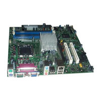
Intel 915G - Matx DDR2-533 LGA775 Product Manual (80 pages)
Desktop Board
Brand:
Intel
| Category:
Motherboard
| Size: 1.72 MB
Table of Contents
Revision History
2
Intended Audience
3
Box Contents
4
Terminology
4
Table of Contents
5
Tables
9
Desktop Board Features
9
Feature Summary
9
Manufacturing Options
11
Supported Operating Systems
11
Desktop Board Components
12
Desktop Boards D915GAV and D915GEV Components
12
Desktop Boards D915GAV and D915GEV Components
13
Intel Desktop Boards D915GUX and D915GAG Components
14
Figures
12
Desktop Boards D915GAG and D915GUX Components
15
Processor
16
Main Memory
17
Desktop Board D915GAV/D915GAG Memory Configurations
17
Intel ® 915G Express Chipset
18
Desktop Board D915GEV/D915GUX Memory Configurations
18
Graphics Subsystem
19
Audio Subsystem
19
Input/Output (I/O) Controller
20
LAN Subsystem (Optional)
20
LAN Subsystem Software
20
RJ-45 LAN Connector Leds
20
Back Panel LAN Connector LED Locations
20
Hi-Speed USB 2.0 Support
21
RJ-45 10/100 Ethernet LAN Connector Leds
21
RJ-45 10/100/1000 Gigabit Ethernet LAN Connector Leds
21
Enhanced IDE Interface
22
Serial ATA
22
Expandability
22
Bios
22
Serial ATA and IDE Auto Configuration
22
PCI and PCI Express Auto Configuration
23
Security Passwords
23
Chassis Intrusion
23
Power Management Features
23
Acpi
23
Power Connectors
24
Fan Connectors
24
Fan Speed Control (Intel ® Precision Cooling Technology)
24
Suspend to RAM (Instantly Available PC Technology)
24
Resume on Ring
25
Location of Standby Power Indicator
25
Wake from USB
26
Wake from PS/2 Keyboard/Mouse
26
PME# Wakeup Support
26
Speaker
26
Battery
26
Real-Time Clock
26
Installing and Replacing Desktop Board Components
27
Before You Begin
27
Installation Precautions
28
Installation Instructions
28
Ensure Electromagnetic Compatibility (EMC) Compliance
28
Chassis and Component Certifications
29
Prevent Power Supply Overload
29
Place Battery Marking
29
Use Only for Intended Applications
30
Installing the I/O Shield
30
Installing and Removing the Desktop Board
31
Desktop Boards D915GEV and D915GAV Mounting Screw Hole Locations
31
Installing and Removing a Processor
32
Installing a Processor
32
Lift Socket Lever
32
Lift the Load Plate and Don't Touch the Socket Contacts
32
Remove the Protective Socket Cover
33
Remove the Processor from the Protective Processor Cover/Do Not Touch
33
Installing the Processor Fan Heat Sink
34
Install Processor
34
Close the Load Plate
34
Connecting the Processor Fan Heat Sink Cable
35
Removing the Processor
35
Connecting the Processor Fan Heat Sink Cable to the Processor Fan Connector
35
Installing and Removing Memory
36
Dual Configuration Example 1
36
Dual Configuration Example 2
37
Dual Configuration Example 3
37
Installing Dimms
38
Matching the Correct DIMM
38
Installing a DIMM
39
Removing Dimms
40
Installing and Removing a PCI Express X16 Card
41
Installing a PCI Express X16 Card
41
Removing the PCI Express X16 Card
41
Inserting the PCI Express X16 Card and Covering the Back Panel VGA Port
41
Connecting the IDE Cable
42
Connecting the Serial ATA (SATA) Cable
43
Connecting the Serial ATA Cable
43
Connecting Internal Headers
44
Internal Headers
44
Installing a Front Panel Audio Solution
45
Front Panel Audio Header Signal Names
45
Connecting USB 2.0 Headers
46
Connecting the Front Panel Header
46
USB 2.0 Header Signal Names
46
Front Panel Header Signal Names
46
Setting up the Flexible 6-Channel Audio with Jack Re-Tasking
47
Back Panel Audio Connectors for Flexible 6-Channel Audio System
47
Connecting Fan and Power Cables
48
Connecting Fan Cables
48
Location of Fan Headers
48
Connecting Power Cables
49
Connecting 2X10 Power Supply Cables
49
Connecting 2X12 Power Supply Cables
50
PCI Bus Add-In Card Connectors
51
Location of the PCI Bus and PCI Express Add-In Card, and Peripheral Interface Connectors for Desktop Boards D915GAV and D915GEV
51
Setting the BIOS Configuration Jumper Block
52
Location of the BIOS Configuration Jumper Block
52
Jumper Settings for the BIOS Setup Program Modes
52
Clearing Passwords
53
Back Panel Connectors
54
Replacing the Battery
55
Removing the Battery
58
Bios
59
Updating the BIOS with the Intel Express BIOS Update Utility
59
Updating the BIOS with the Iflash Memory Update Utility
60
Obtaining the BIOS Update File
60
Updating the BIOS
60
Recovering the BIOS
61
Trusted Platform Module (Optional)
63
System Requirements
63
Warning of Potential Data Loss
63
Security Precautions
64
Password Procedures
64
Emergency Recovery File Back up Procedures
65
Hard Drive Image Backup Procedures
65
Clear Text Backup (Optional)
65
Trusted Platform Module Ownership
66
Enabling the Trusted Platform Module
66
Assuming Trusted Platform Module Ownership
66
Recovery Procedures
67
Clearing Trusted Platform Module Ownership
69
Software Support
69
Desktop Board Resources
71
Memory Map
71
DMA Channels
71
System Memory Map
71
Interrupts
72
A Error Messages and Indicators
73
BIOS Beep Codes
73
Beep Codes
73
BIOS Error Messages
74
B Regulatory Compliance
77
Safety Regulations
77
European Union Declaration of Conformity Statement
77
Product Ecology Statements
78
EMC Regulations
79
Product Certification Markings (Board Level)
80
Product Certification Markings
80
Advertisement
Advertisement
Related Products
Intel DDR266 (PC2100)
Intel DDR333 (PC2700)
Intel DDR400 (PC3200)
Intel DDR266/333
Intel D945PLNM
Intel DB65AL
Intel DG41AN
Intel DH57DD
Intel DBS1200KP
Intel D915PBL
Intel Categories
Motherboard
Computer Hardware
Server
Server Board
Desktop
More Intel Manuals
Login
Sign In
OR
Sign in with Facebook
Sign in with Google
Upload manual
Upload from disk
Upload from URL