Sign In
Upload
Manuals
Brands
Inovance Manuals
Inverter
MD300
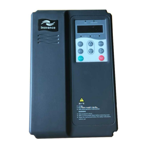
Inovance MD300 Manuals
Manuals and User Guides for Inovance MD300. We have
2
Inovance MD300 manuals available for free PDF download: User Manual
Inovance MD300 User Manual (205 pages)
Advanced Vector Control Inverter
Brand:
Inovance
| Category:
Inverter
| Size: 4 MB
Table of Contents
Precautions
2
Preface
2
Comparison between Traditional Inverter and MD Series Modular Inverter
3
Introduction
3
MD Series Inverter
3
Difference between MD320 and MD300 Functional Modules
4
MD Series Inverter Modular Structure Diagram
5
First Time Use
6
Md320N
6
Unpacking and Inspection
6
Table of Contents
7
Connection to Peripheral Divices
9
Diagram for the Connection to Peripheral Divices
9
Safety and Precautions
10
Before Installation
11
Chapter 1 Safety and Precautions
11
During the Installation
11
Safety Precautions
11
During Wiring
12
Before Power-On
13
Upon Power-On
13
During Repair
14
During the Operation
14
Motor Insulation Inspection
14
Precautions
14
Thermal Protection of the Motor
14
Motor Heat and Noise
15
Running with Frequency Higher than Standard Frequency
15
Switching Devices Like Contactors Used at Input and Output Terminal
15
Vibration of Mechanical Device
15
Altitude and Derating
16
Certain Special Use
16
Lightning Impulse Protection
16
Note of Inverter Disposal
16
Product Information
18
Chapter 2 Product Information
19
Designation Rules
19
Nameplate
19
MD320 Inverter Model and Technical Data
20
MD320 Inverter Series
20
MD320 Inverter Technical Specifications
22
Technical Specifications
22
Physical Appearance and Dimensions of Mounting Hole
24
Physical Appearance of Inverter
25
Schematic Diagram for Physical Dimensions and Mounting Dimensions
25
Physical Dimensions and Mounting Hole Dimensions
27
Physical Dimensions and Mounting Hole Dimensions (MM)
30
Physical Dimensions of External Keyboard
32
Schematic Diagram for Mounting Hole Dimensions of External Keyboard
32
Adaptable Inverter Model
33
Schematic Diagram for Dimensions of External DC Reactor
33
MD320 Inverters Optional Parts
34
Optional Parts
34
Periodic Inspection
36
Routine Inspection Items Include
36
Routine Repair and Maintenance of Inverter
36
Cooling Fan
37
Filter Electrolytic Capacitor
37
Instructions on Warranty of Inverter
37
Replacement of Vulnerable Parts for Inverter
37
Storage of Inverter
37
Guide to Prototyping of Brake Components
38
Prototyping Guide
38
MD320 Inverter Bake Components Prototyping Table
39
Selection of Braking Resistor Power
39
Selection of Resistance Vlaue
39
Mechanical and Electric Installation
42
Chapter 3 Mechanical and Electric Installation
43
Installation Diagram of Upper and down Parts
43
Installation Environment
43
Mechanical Installation
43
Single Unit Installation Diagram
43
MD320 Inverter Installation Diagram
44
Removing and Mounting the Lower Cover Plate
44
Removing the Lower Cover Plate of Plastic Enclosure
44
Removing the down Cover Plate of Plastic Enclosure
45
Removing the Lower Cover Plate of Sheet-Metal Enclosure
45
Electrical Installation
46
Guide to Prototyping of External Electrical Parts of MD320 Inverter
46
Guide to the External Electrical Parts
46
Instruction for the Use of External Electrical Parts of MD320
47
Connections
49
Schematic Diagram for Single-Phase Inverter Connection
49
Schematic Diagram for Three-Phase Inverter Connection
50
Main Circuit Terminals and Connections
51
Diagram for Driver Main Circuit Power Terminal
52
Control Terminal and Connection
54
Earth Terminal PE
54
Function Description of Control Terminal
54
Layout of Control Circuit Terminals
54
Analog Input Terminal
56
Description of Connection of Control Terminals
56
Schematic Diagram for Connection of Input Terminal of Analog Signal
56
Schematic Diagram for Connection of Terminal of Analog Input
56
Connection with Dry Contact Sharing the Negative Pole
57
DI Terminal Connection
57
Digital Input Terminal
57
Connection with Dry Contact Sharing the Positive Pole
58
Source Electrode Connection
58
Digital Output Terminal
59
Drain Electrode Connection
59
Schematic Diagram for Connection of Digital Output Terminal
59
Operation and Display
60
Chapter 4 Operation and Display
61
Description of Function LED Indictor
61
Introduction to Operation and Display Interface
61
Units of LED Indictor Description
61
Description of Function Code Viewing and Modification Methods
62
Digital Display Zone
62
Keyboard Button Description
62
Operation Procedure of Three-Level Menu
63
Shortcut Menu Operation Mode
63
Add Shortcut Parameter Item
64
Example of Adding Shortcut Parameter Item
64
Example of Modification of Shortcut Parameters
64
Modification of Shortcut Parameters
64
Delete Shortcut Parameter Item:
65
Extended Function Menu
65
Method of Viewing Status Parameter
65
Automatic Tuning of Motor Parameters
66
Password Setting
66
Function Parameter Table
68
Chapter 5 Function Parameter Table
69
Parameter Description
94
Chapter 6 Parameter Description
95
Group F0 Basic Function
95
V/F Control
95
Frequency Source Switching
99
Group F1 Motor Parameters
103
Leakage Inductive Reactance
104
Mutual Inductive Reactance
104
Rotor Resistance
104
Stator Resistance
104
Group F2 Vector Control Parameters
105
Tuning Operation Description
105
Recommended Adjustment Method
106
Schematic Diagram of PI Parameter
106
Slip Compensation Coefficient
106
Time Constant of Speed Loop Filter
106
Torque Control
107
Encoder Pulse Number
108
Group F3 V/F Control Parameters
108
Torque Upper Limit Source
108
V/F Curve Setup
108
Cutoff Frequency of Torque Boost
109
Schematic Diagram for Manual Torque Boost
109
Torque Boost
109
Schematic Diagram for V/F Curve Setup
110
Avr
111
Group F4 Input Terminal
111
Oscillation Suppression Gain
111
DI Filter Time
116
Terminal Command Mode
116
Three-Line Running Mode 1
117
Three-Line Running Mode 2
117
AI1 Minimum Input
118
Terminal UP/DOWN Speed
118
Corresponding Relationship between Analog Reference and Setting
119
AI3 Input Filter Time
120
AI3 Maximum Input
120
Group F5 Output Terminal
120
FM Terminal Output Mode Selection
121
FMR Output Selection
121
Direct Start
125
Group F6 Start/Stop Control
125
Rotation Speed Tracking Mode
125
Rotation Speed Tracking Restart
125
Frequency Source Is Digital Reference
126
Frequency Source Is Digital Setup
126
Rotation Speed Tracking Fastness and Slowness
126
DC Brake Current at Start
127
DC Brake Time at Start
127
Speed-Up/Speed-Down Mode
127
Start Segment Proportion of S Curve
127
Schematic Diagram for S Curve Acceleration/Deceleration
128
Brake Use Ratio
129
LCD Language Selection
129
MF.K Key Function Selection
129
QUICK Parameter Lockout
130
STOP/RESET Key Function
130
Group F8 Auxiliary Function
133
Schematic Diagram of Skip Frequency
134
Forward/Reverse Rotation Dead-Zone Time
135
Schematic Diagram for Forward
135
Frequency Detection Value
136
Over Modulation Active
136
Setup Running Time
136
Start Protection Selection
136
Schematic Diagram for Detection Amplitude
137
Schematic Diagram of FDT Level
137
Earth Short Circuit Protection Detection Upon Power-On
138
Running Time to Action Selection
138
Group FA Process Control PID Function
143
PID Feedback Source
144
PID Keyboard Reference
144
Process PID Principle Framework
144
PID Action Direction
145
PID Reference Feedback Range
145
Group FB Swing Frequency, Fixed Length and Count
146
Skip Frequency Working Diagram
146
Swing Frequency Setup Mode
146
Kick Frequency Amplitude 1
147
Setup Length
147
Swing Frequency Amplitude
147
Swing Frequency Cycle
147
Designated Counting Value
148
Group FC MS Speed Function and Simple PLC Function
148
Setup Counting Value
148
MS Speed 15
150
PLC Running Mode
150
Schematic Diagram of Simple PLC
150
Group FD Communication Parameters
154
Group FF Factory Parameters (Reserved)
154
Group FP User Password
154
Parameter Initialization
154
EMC Guide
156
Chapter 7 EMC (Electromagnetic Compatibility)
157
Definition
157
Electromagnetic Interference and Installation Precautions
157
EMC Guide
157
EMC Standard Description
157
Harmonic Effect
157
Leakage Current and Handling
159
Fault Diagnosis and Solution
160
Chapter 8 Fault Diagnosis and Solution
161
Fault Alarm and Countermeasures
161
Inverter Unit Protection (ERR01)
161
Acceleration over Current (ERR02)
162
Deceleration over Current (ERR03)
163
Constant Speed over Current (ERR04)
164
Acceleration over Voltage(ERR05)
165
Constant Speed over Voltage(ERR07)
166
Deceleration over Voltage (ERR06)
166
Control Power Supply Fault(ERR08)
167
Under Voltage Fault(ERR09)
167
Inverter/Motor Overload (ERR10/ERR11)
168
Phase Loss at Input Side(ERR12)
168
Module Overheating (ERR14)
169
Phase Failure at Output Side(ERR13)
169
Communication Fault (ERR16)
170
External Equipment Fault(ERR15)
170
Contactor Fault (Err17)
171
Current Detection Fault (ERR18)
171
Motor Tuning Fault (ERR19)
172
PG Fault (ERR20)
172
Data Overflow (ERR21)
173
Earth Short Circuit Fault(ERR23)
173
Inverter Hardware Fault(ERR22)
173
Common Fault and Resolution
174
Appendix: Card Description
177
Dimensions and Installation
177
Model and Specifications
177
Instruction for Use
178
PG Card Dimension
178
PG Card Terminal Definition
178
Principle Schematic Diagram
179
Schematic Diagram for Encoder Interface
179
Terminal and Toggle Description
179
Application Connection
180
Schematic Diagram for Frequency Division Interface
180
Schematic Diagram for the Connection of Collector Output Encoder
181
Appendix A: Description of Common PG Card (MD32PG)
177
Appendix B: Description of Long-Line Drive PG Card (MD32PG3)
182
PG Card Terminal Description
182
Schematic Diagram for Differential PG Card Structure
182
Appendix C: Description of IO Expansion Card (MD32IO)
183
IO Installation Mode
183
Mechanical Installation and Control Terminal Function
183
Jumper Terminal
184
Physical Dimensions
184
Control Terminal Function
185
Appendix D: Description of Communication Card (MD32MBS)
187
Communication Card Model Description
187
Physical Structure and Connection Mode
187
Installation Mode with Tightening Screws
188
RS-232 Signal Definition
188
RS-485 Signal Definition
188
Appendix E: Description of Parameter Copy Card (MDCP)
189
Definition of Parameter Copy Card
189
Description of Parameter Copy Operation Process
189
Schematic Diagram for Parameter Copy Keyboard
189
About Protocol
190
Appendix F MD320 Serial Communication Protocol
190
Application Method
190
Bus Structure
190
Communication Data Structure
191
Protocol Description
191
RTU Frame Format
191
Master Command Information
192
Slave Responding Information
192
Command Code:06H,Write a Word
193
CRC Checking
193
Group FH Function Parameters
195
Only for Reading Parameter, Can Not be Changed Parameters
195
Digital Output Terminal Control
197
Parameter Locking Command
197
Parameters Locking Password Checksum
197
Read Inverter Status
197
Analog Output AO1 Control: (Write-Only)
198
Analog Output AO2 Control: (Write-Only)
198
Pluse Output Control: (Write-Only)
198
Description Data of Communication Fault Information (Fault Code)
199
Data Format
200
Group FD Communication Parameter Description
200
Local Address
200
Response Delay
200
Advertisement
Inovance MD300 User Manual (96 pages)
Brand:
Inovance
| Category:
Inverter
| Size: 1 MB
Table of Contents
Table of Contents
1
Foreword
3
Chapter 1 Safety and Precautions
7
Safety Issues
7
Precautions
9
Chapter 2 Product Information
12
Designation Rules
12
Nameplate
12
MD300 Inverter Series
13
Technical Specification
14
Configuration and Dimensions
17
Options and Accessories
20
Routine Maintenance of Inverter
21
Instructions on Warranty of Inverter
22
Prototyping Guide
22
Guide to Prototyping of Brake Components
23
Chapter 3 Mechanical and Electrical
25
Installation
25
Mechanical Installation
25
Electrical Installation
29
Chapter 4 Operation and Display
39
Interface
39
Description of Function Code Viewing and Modification Methods
40
Method of Viewing Status Parameter
41
Password Setting
41
Automatic Tuning of Motor Parameters
42
Chapter 5 Function Parameter Table
43
Chapter 6 Parameter Description
55
Group F0 Basic Parameters
55
Group F1 Motor Parameters
61
Parameters
63
Group F3 Terminal Input/Output
65
Group F4 Start/Stop Control Parameters66
68
Group F5 Fault and Protection
69
Group F6 Auxiliary Function
71
Group FF Factory Parameters (Reserved)
75
Group FP User Password
75
Chapter 7 EMC (Electromagnetic Compatibility)
76
Definition
76
EMC Standard Description
76
EMC Introduction
76
Chapter 8 Troubleshooting and
80
Countermeasures
80
Fault Alarm and Countermeasures
80
Common Fault and Resolutions
91
Specification
92
Function Specification
92
Non-Standard Specification
93
Advertisement
Related Products
Inovance MD300A-S0.2BA
Inovance MD300A-S0.7BA
Inovance MD300A-S2.2BA
Inovance MD300A-S0.4BA
Inovance MD300A-T0.7BA
Inovance MD300A-S1.5BA
Inovance MD300A-T1.5BA
Inovance MD300A-T2.2BA
Inovance MD300S0.4
Inovance MD300S0.7
Inovance Categories
Servo Drives
DC Drives
Controller
Control Unit
Inverter
More Inovance Manuals
Login
Sign In
OR
Sign in with Facebook
Sign in with Google
Upload manual
Upload from disk
Upload from URL