Table of Contents
Advertisement
Foreword....................................................... 1
Chapter 1 Safety and Precautions ........... 5
1.1 Safety issues............................................ 5
1.2 Precautions .............................................. 7
Chapter 2 Product Information............... 10
2.1 Designation Rules .................................. 10
2.2 Nameplate.............................................. 10
2.3 MD300 Inverter Series ........................... 11
2.4 Technical Specification .......................... 12
2.5 Configuration and Dimensions ............... 15
2.6 Options and Accessories ....................... 18
2.7 Routine Maintenance of inverter ............ 19
2.8 Instructions on Warranty of Inverter ....... 20
2.9 Prototyping Guide .................................. 20
..................................................................... 21
Installation .................................................. 23
3.1 Mechanical installation ........................... 23
3.2 Electrical Installation .............................. 27
Chapter 4 Operation and Display ........... 37
4.1 Introduction to Operation and Display
Interface ....................................................... 37
Modification Methods ................................... 38
4.4 Password Setting ................................... 39
Chapter 5 Function Parameter Table ..... 41
Contents
Group F0 Basic parameters ................. 53
Group F1 Motor Parameters................. 59
Group F2 Vector and VF Control
Parameters ........................................... 61
Group F3 Terminal input/output............ 63
Group F5 Fault and Protection ............. 67
Group F6 Auxiliary Function ................. 69
.............................................................. 73
Group FP User Password..................... 73
Compatibility) ...................................... 74
7.1 Definition ........................................ 74
7.2 EMC Standard Description ............. 74
7.3 EMC Introduction............................ 74
Countermeasures ............................... 78
8.2 Common Fault and Resolutions ..... 89
Attachment Non-standard
Specification........................................ 90
Attachment A: MD300 Frequency Switching
- Line Speed Displaying Non-standard
Function Specification ........................... 90
Attachment B: MD300 with FDT Function
Non-standard Specification ................... 91
efesotomasyon.com
Advertisement
Table of Contents

Subscribe to Our Youtube Channel
Related Manuals for Inovance MD300 Series


Summary of Contents for Inovance MD300 Series
-
Page 1: Table Of Contents
Contents Foreword............1 Chapter 6 Parameter Description ... 53 Chapter 1 Safety and Precautions ... 5 Group F0 Basic parameters ....53 1.1 Safety issues..........5 Group F1 Motor Parameters....59 1.2 Precautions ..........7 Group F2 Vector and VF Control Chapter 2 Product Information.... - Page 2 efesotomasyon.com...
-
Page 3: Foreword
Foreword Foreword series inverter MD Series Inverter generation high-performance Specialized Top-layer Industrial Module Module modular inverter launched Shenzhen Inovance Technology Co., Traditional General-Purpose Middle-layer Inverter Module Module Ltd, which represents future development direction of the inverter. High-Performance Bottom-layer Unlike traditional inverters, MD series... - Page 4 Foreword Table 1 Difference between MD300 and MD320 Functional Modules MD320 MD300 5×DI (bidirectional input high-speed 4×DI (single directional input, one Input/output terminal port),2×AI 2×DO (one high-speed port), 2×AI 1×DO 1×AO high-speed port), 1×AO 1×Relay 1×Relay (expandable I/O) Control mode SVC, VC and V/F SVC and V/F Multiple-point fold line mode, which is...
- Page 5 Foreword 3) The top-layer module of MD series inverter is used special for the industry, which offers solution platform according to the industrial demand. Customers can use the existing solution or perform second development according to their own needs. Refer to Fig.2 for the top sub-module Ethernet MD320 Control Module MD300 Control Module...
- Page 6 The supporting equipment customers shall MD300 series inverter complies with the distribute this manual together with the following international standards and part of equipment to the final users.
-
Page 7: Chapter 1 Safety And Precautions
Chapter 1 Safety and Precautions Chapter 1 Safety and Precautions Safety definition: Note Note In this manual, safety precautions 2. When more than two inverters are to are divided into two types below: be installed in one cabinet, due attention shall be paid to the installation locations Danger Danger... - Page 8 Chapter 1 Safety and Precautions 4. Whether all the external fittings are Note Note connected correctly in accordance with the circuit provided in this manual. 5. Do not connect the input power cable Otherwise accident may occur! to the output ends U, V and W. Otherwise it may damage the inverter.
-
Page 9: Precautions
Chapter 1 Safety and Precautions 1.1.6 During the operation: indictor inverter OFF. Otherwise, the residual charge on the Danger Danger capacitor may cause personal injury! 3. The repair and maintenance for 1. Do not approach the mechanical inverter can only be performed by equipment when selecting the restart professional technicians. - Page 10 Chapter 1 Safety and Precautions the mechanical devices into consideration. the allowable working voltage range as specified in this manual, it is easy to damage 1.2.4 Motor Heat and Noise Since the output voltage of inverter is the devices in the inverter. When necessary, PWM wave and contains certain harmonics, use the corresponding step-up or step-down the temperature rise, noise and vibration of...
- Page 11 Chapter 1 Safety and Precautions Please dispose the inverter as industrial heat of the motor. wastes. 3) Since the inverter has built-in standard 1.2.13 Adaptable Motor parameters of the adaptable motors, it is 1) The standard adaptable motor is necessary perform motor parameter...
-
Page 12: Chapter 2 Product Information
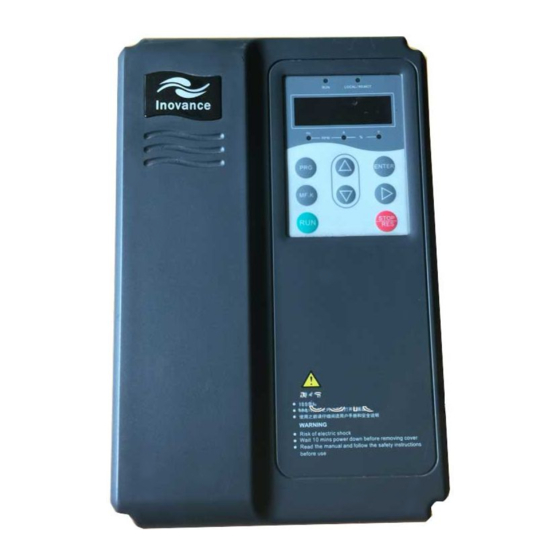
Chapter 2 Product Information Chapter 2 Product Information 2.1 Designation Rules Brake Unit Mark Inverter Series Null None Mark Voltage Level Including Brake Unit Single Phase 220V Model Mark Three Phase 380V embedded in the Null operation panel Compatible connected to the Motor Power operation panel Mark... -
Page 13: Md300 Inverter Series
Chapter 2 Product Information 2.3 MD300 Inverter Series Table 2-1 MD300 Inverter Model and Technical Data Power Input Output Adaptable Inverter Input supply current current Motor model voltage capacity kava MD300S0.4 Single-phase MD300S0.7 0.75 220V Range: MD300S1.5 14.2 -15% 20% MD300S2.2 23.0 MD300T0.7... -
Page 14: Technical Specification
Chapter 2 Product Information 2.4 Technical Specification Table 2-2 MD300 Inverter Technical Specifications Item Specifications maximum frequency 300Hz 0.5k to 16kHz; the carrier frequency will be Carrier frequency automatically adjusted according load characteristics. Input frequency Digital setting: 0.01Hz resolution Analog setting: maximum frequency ×0.1% Control mode Open-loop vector control (SVC) V/F control... - Page 15 Chapter 2 Product Information Item Specifications Programmable key: Select the command channel MF.K Key switching/forward and reverse rotations/jog operation. running command Two kinds of channels: Operation panel reference, channel control terminal reference Multiple frequency sources: digital reference, analog voltage reference, analog current reference and pulse Frequency source Input reference.
- Page 16 Chapter 2 Product Information Item Specifications If the altitude is lower than 1000m, higher than altitude 1000m, please derate it for use. (derated when used in the ambient ambient temperature temperature of 40 to 50 ) Humidity Less than 95%RH, without condensing Vibration Less than 5.9 m/s (0.6g)
-
Page 17: Configuration And Dimensions
Chapter 2 Product Information 2.5 Configuration and Dimensions 2.5.1 Physical Appearance Upper Operation Panel Cover Plate Lower Cover Plate I/O Port Bottom Mounting Hole Inverter Nameplate Fig.2-3 Physical Appearance of Inverter Configuration & dimensions of outer keypad Mounting hole size of outer keypad Fig. - Page 18 Chapter 2 Product Information Fig. 2-5 Schematic Diagram for Configuration & Mounting Dimensions of 0.4kW 15kW Inverter Fig. 2-6 Inverter of 18.5kW 90kW -16- efesotomasyon.com...
- Page 19 Chapter 2 Product Information 2.5.2 Mounting hole size Table 2-3 Mounting hole size of MD300 inverter -17- efesotomasyon.com...
-
Page 20: Options And Accessories
Chapter 2 Product Information 2.6 Options and Accessories Table 2-4 MD300 Inverter Options and Accessories Name Model Function Remarks Single-phase slave built-in The letter “B” brake unit (0.4kW to 2.2kW), Three-phase slave attached optional three-phase slave built-in brake unit of Built-in brake behind the from 0.75kW to 2.2kW;... -
Page 21: Routine Maintenance Of Inverter
Chapter 2 Product Information The dust on the surface of the inverter 2.7 Routine Maintenance of shall be effectively removed, so as to prevent the dust entering the inverter. inverter Especially the metal dust is not allowed. 2.7.1 Routine Maintenance The oil stain on the inverter heatsink fan influence ambient... -
Page 22: Instructions On Warranty Of Inverter
Chapter 2 Product Information replacement according to the operating time. as indicated on the barcode) for the failure or 1. Cooling fan damage under normal use conditions. If the Possible reason for damage: Bearing is equipment has been used for over 18 months, worn and blade deteriorates. -
Page 23: Guide To Prototyping Of Brake Components
Chapter 2 Product Information capacity as specified in the instruction manual. Generally, such load requires strong Due attention shall be paid to the comparison mechanical characteristics at the low speed between the rated currents of motor and so as to meet the dynamic and static index inverter. - Page 24 Chapter 2 Product Information Table 2-5 MD300 Inverter Bake Components Prototyping Table Recommended Recommended Inverter Braking Power of Brake Resistance Value Remarks model unit Resistor of Brake Resistor MD300S0.4 MD300S0.7 The letter “B” is MD300S1.5 100W Built-in, attached MD300S2.2 100W optional behind the Inverter model.
-
Page 25: Chapter 3 Mechanical And Electrical
Chapter 3 Mechanical and Electrical Installation Chapter 3 Mechanical and Electrical Installation 3.1 Mechanical installation 1. Installation environment: 1) Ambient temperature: The ambient temperature exerts great influences on the service life of the inverter and is not allowed to exceed the allowable temperature range (-10 to 50 ). - Page 26 Chapter 3 Mechanical and Electrical Installation Note: When the inverter power is not higher Note:When inverters are than 22kW, the A size can be omitted. When distributed up and down, mount the inverter power is higher than 22kW, the A splitter for heat insulation as shown size shall be higher than 50mm.
- Page 27 Chapter 3 Mechanical and Electrical Installation 2) The mounting space shall be as indicated as Fig.3-1, so as to ensure the heat dissipation space of the inverter. However, the heat dissipation of other devices in the cabinet shall also be taken into account.
- Page 28 Chapter 3 Mechanical and Electrical Installation Lower Cover Plate Fig.3-3 Removing the Lower Cover Plate of Sheet-Metal Enclosure -26- efesotomasyon.com...
-
Page 29: Electrical Installation
Chapter 3 Mechanical and Electrical Installation 3.2 Electrical Installation 1. Prototyping guidance to the peripheral electrical components: Table 3-1 Guide to Prototyping of Peripheral Electrical Components of MD300 Inverter Recommen Recommen Recomme nded Circuit Recom Conducting Grounding Conducting Conducti Inverter breaker mended Wire of... - Page 30 Chapter 3 Mechanical and Electrical Installation Mounting Part Name Function description Location Circuit Front end of Disconnect the power supply when the equipment at the breaker input circuit lower level is over current. Between the Connection and disconnection of inverter. Frequent circuit breaker power-on and power-off operations (Not more than twice Contactor...
- Page 31 Chapter 3 Mechanical and Electrical Installation 3. Connections Brake Resistor Single-phase Input Power Earth Connection External Keyboard Interface Multifunctional Digital Input Terminal 1 Multifunctional Digital Input Terminal 2 Multifunctional Digital Input Terminal 3 Multifunctional Digital Input Terminal 4 Multifunctional Expansion Card Analog Output: Frequency Source:...
- Page 32 Chapter 3 Mechanical and Electrical Installation Brake Resistor Single-phase 380V Input Power Earth Connection External Keyboard Interface Multifunctional Digital Input Terminal 1 Multifunctional Digital Input Terminal 2 Multifunctional Digital Input Terminal 3 Multifunctional Digital Input Terminal 4 Multifunctional Expansion Card Analog Output: Frequen cy Source:...
- Page 33 Chapter 3 Mechanical and Electrical Installation Brake Resistor Single-phase 380V Input Power Earth Connection External Keyboard Interface Multifunctional Digital Input Terminal 1 Multifunctional Digital Input Terminal 2 Multifunctional Digital Input Terminal 3 Multifunctional Digital Input Terminal 4 Multifunctional Expansion Card Analog Output: Frequency Source:...
- Page 34 Chapter 3 Mechanical and Electrical Installation Brake Resistor reactor Sing le-pha se 380 V Inpu t Power Earth Conne ction Externa l Keyboa rd Interface Multifun ctiona l Digital Inpu t Term ina l 1 Multifunctiona l Digital Inpu t Term ina l 2 Multifun ctiona l Digital Inpu t Term ina l 3 Multifunctiona l Digital...
- Page 35 Chapter 3 Mechanical and Electrical Installation 4. Main Circuit Terminals and Connections Danger Danger 1) The wiring operation is enabled only after confirming that the power switch is OFF. Otherwise, electric shock may be caused! 2) The wiring operation can only be performed by professional technicians. Otherwise, it may cause harm to equipment and human! Reliable grounding is required.
- Page 36 Chapter 3 Mechanical and Electrical Installation Terminals Name Description terminals of DC bus Connecting terminal of brake (+) and PB resistor U, V and W Output terminal of inverter Connect the three-phase motor Earth terminal Earth terminal 3) Notes on Wiring: A.
- Page 37 Chapter 3 Mechanical and Electrical Installation 2. Description of Control Terminal Function: Terminal Terminal Type Function description Symbol name Provide +10V power supply for external units, External 10V and the maximum output current is 10mA. +10V-GND power supply It is generally used as the operating power of external potentiometer.
- Page 38 Chapter 3 Mechanical and Electrical Installation 3) Wiring of control terminal: conducting weak signal. A. Analog input terminal: If the ON/OFF signals to the digital input Generally, it is required to use shielding terminal of inverter are provided by open cable and the wiring distance shall be as collector output, it is necessary to take the shorter as possible (not longer than 20m), as...
-
Page 39: Chapter 4 Operation And Display
Chapter 4 Operation and Display Chapter 4 Operation and Display 4.1 Introduction to Operation and Display Interface Change to the functional parameters, operating status monitoring and running control (startup, stop) of the inverter can be realized on the operation panel. The outline and functional area are shown as Fig.4-1: Fig.4-1 Operation Panel Diagram 1) Description of Function LED Indictor:... -
Page 40: Description Of Function Code Viewing And Modification Methods
Chapter 4 Operation and Display Five-digit LED display, able to display setup frequency, output frequency, various monitoring data and alarm code. 4) Keyboard button description Table 4-1 MD300 inverter keypad button description Button Name Function programming Enter into/ exit from level 1 menu confirmation enter the menu interfaces level by level, and confirm the ENTER... -
Page 41: Method Of Viewing Status Parameter
Chapter 4 Operation and Display Note: When operating on level 3 menu, statuses can be cyclically displayed through press PRG key or ENTER key to return to pressing shift key. Under the stop status, level 2 menu. The difference between PRG there are five status parameters of MD300 key and ENTER key is described as follows: inverter can be displayed cyclically through... -
Page 42: Automatic Tuning Of Motor Parameters
Chapter 4 Operation and Display entered until user password is entered F1-08: leakage inductive reactance correctly. F1-09: mutual inductive reactance cancel password protection F1-10: No-load excitation current function, enter with password and set FP-00 Finally, complete the automatic tuning of to “0”. -
Page 43: Chapter 5 Function Parameter Table
Chapter 5 Function Parameter Table Chapter 5 Function Parameter Table If FP-00 is set to non-zero value, it means parameter protection password is set, and the parameter menu cannot be opened until correct password is entered. To cancel the password, it needs to set FP-00 to “0”. - Page 44 Chapter 5 Function Parameter Table Factory Minimum Cha- Code Name Setup range default unit value 0: invalid Auxiliary 1: valid (auxiliary frequency F0-03 Frequency source source AI2, which can be 0, 1 × Y selection and 2 only corresponding with F0-02) 0.00 to upper limit frequency (It Digital preset...
- Page 45 Chapter 5 Function Parameter Table Factory Minimum Cha- Code Name Setup range default unit value 6: Terminal UP 7: Terminal DOWN 8: coast to stop 9: Fault reset (RESET) 10: Reserved External fault normally open input 12: MS speed terminal 1 13: MS speed terminal 2 External fault...
- Page 46 Chapter 5 Function Parameter Table Factory Minimum Cha- Code Name Setup range default unit value 0: Running frequency 1: Setup frequency 2: Output current AO output F0-14 3 PULSE input (corresponding selection setup) 4: AI1 (corresponding setup) 5: AI2 (corresponding setup) 0: Direct start F0-15 Start mode...
- Page 47 Chapter 5 Function Parameter Table Factory Minimum Cha- Code Name Setup range default unit value Mutual inductive model F1-09 0.01mH 655.35mH 0.1 mH reactance dependent model F1-10 No-load current 0.0A 650.00A 0.01A dependent 0: no operation F1-11 Tuning selection 1: static tuning ×...
- Page 48 Chapter 5 Function Parameter Table Factory Minimum Cha- Code Name Setup range default unit value Vector control F2-08 5.0% 200.0% 0.1% 150.0% torque upper limit V/F control slip F2-09 compensation 0.0% 200.0% 0.1% 0.0% factor V/F control F2-10 vibration 0 100 suppression gain Group F3 Terminal Input and Output Terminal control...
- Page 49 Chapter 5 Function Parameter Table Factory Minimum Cha- Code Name Setup range default unit value PULSE (pulse) F3-10 input maximum 0.00kHz 50.00kHz 0.01Hz 50.00kHz frequency F3-11 input filter time 0.01s 10.00s 0.01s 0.01s AO zero offset F3-12 -100.0% 100.0% 0.1% 0.1% coefficient F3-13...
- Page 50 Chapter 5 Function Parameter Table Factory Minimum Cha- Code Name Setup range default unit value Stall gain over F5-04 0(no stall over voltage) current Stall point over F5-05 100% 200% 150% current Fault auto reset F5-06 times Fault auto reset F5-07 0.1s to 100.0s 0.1s...
- Page 51 Chapter 5 Function Parameter Table Factory Minimum Cha- Code Name Setup range default unit value 0: No fault 1: Inverter unit protection (ERR01) 2: Acceleration over current (ERR02) 3: Deceleration over current (ERR03) 4: Constant speed over current (ERR04) 5: Acceleration over voltage(ERR05) 6: Deceleration over voltage(ERR06)
- Page 52 Chapter 5 Function Parameter Table Factory Minimum Cha- Code Name Setup range default unit value Frequency upon F5-11 0.01Hz 0.00Hz fault F5-12 Current upon fault - 0.01A 0.00A Bus voltage upon F5-13 0.1V 0.0V fault Group F6 Auxiliary Function maximum output F6-00 50.00Hz 300.00Hz 0.01Hz...
- Page 53 Chapter 5 Function Parameter Table Factory Minimum Cha- Code Name Setup range default unit value 0: No function Switching between local MF.K Key function operation and remote operation F6-11 × selection 2: Switching between forward rotation and reverse rotation 3 jog The RESET function for all statuses is available STOP/RESET key...
- Page 54 Chapter 5 Function Parameter Table Factory Minimum Cha- Code Name Setup range default unit value Group FF Factory Parameters Manufacturer FF-00 0 65535 password FP User password and parameter initialization user password FP-00 0 65535 0: no operation Parameter 1: Restore factory default setup FP-01 ×...
-
Page 55: Chapter 6 Parameter Description
Chapter 6 Parameter Description Chapter 6 Parameter Description command. Group F0 Basic parameters The inverter control command includes start, Factory default Control stop, forward rotation, reverse rotation and value mode Jog. Non-speed sensor Keypad control (“LOCAL/REMOT” LED F0-00 vector control Setup OFF) range... - Page 56 It means that the frequency is determined inverter. by the analog input terminal. MD300 series inverter standard unit provides two analog input terminals, where AI1 is 0V-10V voltage input, but AI2 can be 0V-10V voltage input or -54- efesotomasyon.com...
- Page 57 Chapter 6 Parameter Description The fan and pump loads may select square Acceler Factory V/F control. F0-05 ation default 20.0 0: Straight V/F curve. It is suitable for time value common constant torque load. Deceler Factory 2: Square V/F curve. It is suitable for the ation default...
- Page 58 Chapter 6 Parameter Description Factory terminal Function Description F0-09 default (Forward function value rotation) selection (REV) Factory This terminal is used to terminal (Forward F0-10 default confirm that the inverter function rotation value Three-line running mode Jog) selection mode three-line control mode Factory running For detailed description,...
- Page 59 Chapter 6 Parameter Description Function Description Function Description the inverter control. input is the general method Reference adopted when there is switch It is enabled only when huge load between F0-02 frequency source requirement for the stop AI1 and selects AI1 or AI2 time.
- Page 60 Chapter 6 Parameter Description Corresp Frequency Please refer to F6-10 Frequen onding arrival for details. cy Setup Paramet output selection Factory speed 0 speed 0 default (Analog F0-14 value output speed 1 speed 1 terminal Setup range speed 2 speed 2 The standard for analog output is from 0mA to 20mA (or from 0V to 10V).
-
Page 61: Group F1 Motor Parameters
Chapter 6 Parameter Description 1: Rotation speed tracking restart Variable frequency The inverter judges the rotation speed and asynchronous direction of the motor firstly and then starts at motor the frequency of the tracked rotation speed of permenant the motor. The rotating motor will be started magnetic smoothly without surge (The trace frequency synchronous... - Page 62 Chapter 6 Parameter Description normally completed, the setup values of F1-06 Note Note to F1-10 will be automatically updated. Each time when the rated power of the motor 1. Please set the parameters according to F1-01 changed, inverter will the nameplate parameters of the motor. automatically recover the parameter values of Accurate motor parameters shall be “F1-06 to F1-10”...
-
Page 63: Parameters
Chapter 6 Parameter Description acceleration time of F0-05 and maintain for Vector certain period of time. Then the motor will control Factory decelerate to zero speed in accordance with speed loop default 0.50s F2-01 the setup acceleration time of F0-06, and by integration value this time the rotary tuning is completed. - Page 64 Chapter 6 Parameter Description frequency 2 is linear switching between two Vector Factory groups of PI parameters. control slip default 100% F2-06 compensat value Parameter ion factor Setup range 50% 200% The parameter is used to adjust steady speed precision when loading to the motor: When the motor is heavy loaded, the speed is lower, the parameter shall be increased, otherwise, decrease the parameter.
-
Page 65: Group F3 Terminal Input/Output
Chapter 6 Parameter Description “Disabled only at the time of deceleration” can control Factory greatly reduce the possibility of over voltage oscillation default fault alarm. When there is brake resistor or it suppression F2-10 value has not need for fast deceleration, select AVR gain “Always Enabled". - Page 66 Chapter 6 Parameter Description 2: Three-line running mode : In this mode, Dln change rate when setting the frequency. is enabled terminal, and the direction is Factory controlled by FWD and REV respectively. minimum default 0.00V F3-02 However, the pulse is enabled through input value disconnecting the signal of Dln terminal when...
- Page 67 Chapter 6 Parameter Description Factory input maximum Factory default 0.01s F3-11 filter time input default 100.0% value F3-09 correspon value Setup range 0.01s to 10.00s ding setup This group of function code defines the Setup range -100.0% 100.0% corresponding relationship when the pulse is above function codes...
-
Page 68: Group F4 Start/Stop Control Parameters66
Chapter 6 Parameter Description value is zero, it indicates there is no DC brake Group F4 Start/Stop Control process, and the inverter will stop according to Parameters the setup decoration to stop process. DC brake Factory Factory Brake use beginning 0.00 default default... -
Page 69: Group F5 Fault And Protection
Chapter 6 Parameter Description Factory Group F5 Fault and Protection Stall gain default over voltage Factory Motor overload value default protection It adjusts the selection value inverter’s capacity in 0: The inverter has suppressing the stall no overload over voltage. The protection for the bigger the value is, motor, and thermal... - Page 70 Chapter 6 Parameter Description Factory Stall gain Fault auto Factory default over current reset default 1.0s value interval value It adjusts the inverter’s Select time capacity in suppressing F5-07 interval the stall over current. Setup range between fault The bigger the value is, 0.1s 100.0s occurring and...
-
Page 71: Group F6 Auxiliary Function
Chapter 6 Parameter Description Inverter load Factory Group F6 Auxiliary Function lost protection default Factory maximum selection value default 50.0Hz output Select whether to F6-00 frequency value provide protection Setup for load loss. When 50.00Hz 300.00Hz range selecting load loss It is used to set the maximum output F5-09 Setup... - Page 72 Chapter 6 Parameter Description reduced, resonance mode 0 (F0-16, deceleration time to stop). mechanical system can be avoided, so that Factory the leakage current to the earth and the acceleration default 20.0s F6-05 interference of the inverter can be reduced. time value When the carrier frequency is low, the output...
- Page 73 Chapter 6 Parameter Description outputting zero frequency. be used to adjust the detection amplitude, as shown in the following figure. Output Frequency Forward Rotation Output Frequency RUNNING Detected TIME Amplitude Time Frequency Detection Signal Dead Zone Time Reverse Rotation Fig.6-6 Schematic diagram for Time Forward/ Reverse Rotation Dead-zone Time Fig.6-7 Schematic Diagram for Detection...
- Page 74 Chapter 6 Parameter Description remote operation. It refers to switching of inverter has short-time output at the instance command source, switching from the current of power-on. command source to the keyboard control Factory (local operation). If the current command speed 0 default value source is keyboard control, this command is F6-14...
-
Page 75: Group Ff Factory Parameters (Reserved)
Chapter 7 EMC (Electromagnetic Compatibility) Group FF Factory Parameters (Reserved) Group FP User Password user password Factory default value FP-00 Setup range 0 65535 Any non-zero number can be set, and then the password protection function will be enabled. 0000 Password protection function disabled Upon setup and validation of the user password, when the user enters the parameter setting status again, the user can view the parameters only and cannot modify the parameter if the password is incorrect. -
Page 76: Chapter 7 Emc (Electromagnetic Compatibility)
Chapter 7 EMC (Electromagnetic Compatibility) Chapter 7 EMC (Electromagnetic Compatibility) group interference rejection, ESD interference 7.1 Definition rejection and power low frequency end Electromagnetic compatibility is the interference rejection (specific test items ability of the electric equipment to run in the including: 1. - Page 77 Chapter 7 EMC (Electromagnetic Compatibility) detection line employ shielded cable The earth wires of the Inverter and other electric products shall be well and the shielding layer shall be grounded; earthed reliably. 7.3.4 Handling method The power input and output power cables of the inverter and weak current interferences inverter...
- Page 78 Chapter 7 EMC (Electromagnetic Compatibility) also an effective method to remove When equipment suffering interferences and the inverter use the the leakage current. same power supply, it may cause The leakage current may increase conduction interference. If the above following the addition of circuit current. methods cannot remove...
- Page 79 Chapter 7 EMC (Electromagnetic Compatibility) installing cabinet in large area and same public earth. Otherwise the have good conduction continuity. EMC effect may be greatly affected. Otherwise there may be danger of The filter shall be installed at a place electric shock and the EMC effect close to the input end of the power may be greatly affected.
-
Page 80: Chapter 8 Troubleshooting And
Chapter 8 Troubleshooting and Countermeasures Chapter 8 Troubleshooting and Countermeasures 8.1 Fault Alarm and Countermeasures MD300 inverter has 20 pieces of warning information and protection function. In case of abnormal fault, the protection function will be invoked, the inverter will stop output, and the faulty relay contact of the inverter will start, and the fault code will be displayed on the display panel of the inverter. - Page 81 Chapter 8 Troubleshooting and Countermeasures Acceleration over current Check if the output loop of the Perform troubleshooting inverter is earthed or short circuited If the motor parameters are identified Identify the motor parameters V/F Mode If the acceleration time is too short Prolong the acceleration time If the manual boost torque Adjust the manual boost...
- Page 82 Chapter 8 Troubleshooting and Countermeasures Deceleration over current Check if the output loop of the Perform troubleshooting inverter is earthed or short circuited Identify the motor parameters If the motor parameters are identified V/F Mode If the deceleration time is too short Prolong the deceleration time Adjust the voltage If the voltage is too low...
- Page 83 Chapter 8 Troubleshooting and Countermeasures Constant Speed over Current Perform troubleshooting, and install Check if the output loop of the inverter is output reactor if the line is too long short circuited or has leakage current Identify the motor parameters If the motor parameters are identified If load is added suddenly Remove the additional load...
- Page 84 Chapter 8 Troubleshooting and Countermeasures Deceleration over voltage If the input voltage is too high Adjust the voltage to normal range f there are external forces Remove the external forces driving the motor to run during or install brake resistor the acceleration process.
- Page 85 Chapter 8 Troubleshooting and Countermeasures Control power supply Adjust the voltage to the range as If the input voltage is within the range specified by the specifications as specified by the specifications Ask for technical support Fig.8-8 Control power supply fault ERR08 Under voltage fault Reset the fault If there is transient power failure...
- Page 86 Chapter 8 Troubleshooting and Countermeasures Inverter Overload Motor overload If the motor protection parameter Set this parameter properly F9-01 is set properly Reduce the load and check If the load is too heavy or motor does not rotate the motor and machinery The inverter model is small Fig.8-10 Inverter/Motor Overload ERR10/ERR11...
- Page 87 Chapter 8 Troubleshooting and Countermeasures Phase loss at the output side Check if the cable connecting the Perform troubleshooting inverter to the motor is normal Check if the three-phase output of the Check if the three-phase running inverter without motor is balanced winding of the motor is normal Ask for technical support and remove the fault...
- Page 88 Chapter 8 Troubleshooting and Countermeasures External equipment fault If it is stopped by pressing the STOP key Reset to run in the non-keyboard operation mode If it inputs external fault signal via Check and remove the multifunctional terminal DI the external fault Stop the unit with the key STOP Reset to run under stall condition...
- Page 89 Chapter 8 Troubleshooting and Countermeasures Motor tuning fault If the motor parameters are set as Set the motor parameters correctly per the motor nameplate Check the cable connecting If the parameter identification the inverter to the motor process is delayed Fig.8-16 Motor Tuning Fault ERR19 Data Overflow Ask for technical support...
- Page 90 Chapter 8 Troubleshooting and Countermeasures Fault of Short Circuit to Earth Replace the cable or motor Detect if the motor is short circuited to earth Replace the drive board Fig.8-19 Earth short circuit fault ERR23 -88- efesotomasyon.com...
-
Page 91: Common Fault And Resolutions
Chapter 8 Troubleshooting and Countermeasures 8.2 Common Fault and Resolutions During the inverter using process, the following faults may occur. Please conduct simple fault analysis by referring to the methods below: 1 No display upon power-on 1) Check whether the inverter input power supply is consistent with the inverter rated voltage with universal meter. -
Page 92: Specification
Attachment Non-standard Specification Attachment Non-standard Specification Attachment A: MD300 Frequency Switching – Line Speed Displaying Non-standard Function Specification The non-standard products have two modifications based on general-purpose MD300: 1. Modification to the frequency source setup: When set frequency source to analog value, the frequency source can be switched between analog value and digital setting F0-04 through external terminal. -
Page 93: Non-Standard Specification
Attachment Non-standard Specification Attachment B: MD300 with FDT Function Non-standard Specification The product is the non-standard inverter of MD300 with frequency detection value satisfied FDT function, it outputs ON/OFF signal for showing whether FDT is satisfied through DO terminal. Hence, the following changes are made based on MD300 general products: AI sets curve with two points F3-02~F3-05. - Page 94 efesotomasyon.com...
- Page 95 If there is any problem during the service, please contact the agent of our company or our company directly. Shenzhen Inovance Technology Co., Ltd. This agreement shall be interpreted by Shenzhen Inovance Technology Co., Ltd.
- Page 96 Product Warranty Card Add. of unit: Customer Name Contact person: information unit: Tel.: P.C.: Product model: Body barcode (Attach here): Product information Name of agent: (Maintenance time and content): Failure information Maintenance personnel: efesotomasyon.com...
Need help?
Do you have a question about the MD300 Series and is the answer not in the manual?
Questions and answers