Sign In
Upload
Manuals
Brands
InoTec Manuals
Industrial Equipment
inoCOMB Cabrio
InoTec inoCOMB Cabrio Manuals
Manuals and User Guides for InoTec inoCOMB Cabrio. We have
1
InoTec inoCOMB Cabrio manual available for free PDF download: Original Operating Manual
InoTec inoCOMB Cabrio Original Operating Manual (73 pages)
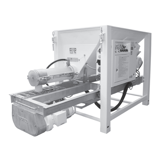
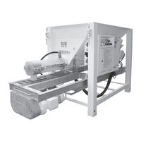
Small Silo
Brand:
InoTec
| Category:
Industrial Equipment
| Size: 10 MB
Table of Contents
Table of Contents
3
1 General Information
6
Information about this Manual
6
Symbol Explanation
6
Purpose of this Operating Manual
6
Disclaimer
6
Warranty
6
Exercising Claims
6
Warranty Claims
7
Carrying out Repairs
7
2 Safety
7
Intended Use
7
General Risk Sources
8
Notices in the Operating Manual
8
Performing Checks before Starting Work
8
Conversions and Changes
9
Cleaning and Maintaining the Machine
9
Changing the Location of the Machine
9
Notices on the Machine
9
Personnel Qualification
10
Responsibility of the Operator
10
Personal Protective Equipment (PPE)
10
3 Technical Data
11
Rating Plate
11
Electric Control System, Pump Output, Particle Size, Weight, Dimensions
11
Mortar Pressure Gauge
11
Water Measuring System
11
Material Container
11
Mixer Motor
11
Pump Motor
11
Metering Shaft
11
Mixing Shaft
11
Rotor/Stator
12
Noise Emission
12
Operating Conditions
12
4 Assembly and Function
12
Scope of Delivery Inocomb Cabrio
12
Functionality
12
Sequence of Assembly
13
Components
14
Description of the Components
14
Frame with Pull-Out Frame for Pump Hopper, Material Hopper, Water Supply Button and Vibrator
15
Switching Cabinet
15
Drive Unit for the Mixer
15
Water Measuring System
15
Mixing Tube Inopower MIX with Mixing Shaft and Mixing Tube Cover
15
Drive Unit for the Feed Pump, Incl. Chain Gear Box and Pump Hopper
15
Displays and Controls
16
Switching Cabinet
16
Pump On/Off Switch and Reset
16
Mixer On/Off Switch
16
Reverse Pump
16
Probe On/Off
16
Pump Speed
16
Illuminated Button Cover Grille
16
Illuminated Button Water Pressure
16
Illuminated Sensor Mortar Pressure
16
Pump Unit (Pump Motor, Pump Shaft, Rotor/Stator and Mortar Pressure Gauge)
17
Mixing Unit (Metering Shaft and Mixing Tube with Mixing Shaft)
17
Water Measuring System
17
Installing the Water Measuring System
18
Connections
18
Power Connections (230 / 400 V)
18
Connections of the Water Measuring System
19
Operating Modes
19
Spare Parts and Diagrams
24
Overview of the Individual Assemblies of the Small Silo
24
Drive Unit for the Mixer
25
Pump Hopper
26
Drive Unit Incl. Chain Gear Box and Pump Hopper
27
Drive Shaft in the Pump Hopper
28
Water Measuring System
29
Switching Cabinet Inside (Level 1)
30
Switching Cabinet Inside (Level 2)
31
Switching Cabinet Left and Right Side, Underside
31
Switching Cabinet Front
32
Mixing Tube Inopowermix "S" Plus with Mixing Shaft and Mixing Tube Cover
33
Mixing Tube Cover for Inopowermix "S" & "L" Mixing Tube (Art. No. 10044008)
34
Mixing Shaft for Inopowermix "S" & "L" Mixing Tube
34
Metering Shaft
34
Pump Shaft for Set "D" and "Ü
35
Rotor/Stator
35
Set "D
36
Set "Ü1
36
Set "Ü2
37
Set "RS
37
5 Transport and Storage
38
Safety Instructions for Transport
38
Transport Inspection
38
Damage Report
38
Complaints
38
Packaging
38
Transporting the Used Machine in the Vehicle
38
Storage
38
6 Installation
39
Delivery Condition of the Machine
39
Assembling the Pump Unit (Pump Shaft, Rotor, Stator and Pressure Gauge with Hose Coupling)
40
Mounting the Metering and Mixing Shaft with Mixing Tube
40
Installing the Water Measuring System
41
Regulation of the Water Pressure
42
Material Preparation
42
Adjusting the Material Consistency
42
Preparing the Machine
42
Starting the Machine
43
7 Commissioning
43
Adding Material to the Material Hopper
43
Changing the Material
43
Change of Location on the Construction Site
44
8 Operation, Use
44
Checking Operating Behaviour
44
Checking the Consistency of the Material
44
Correcting Flow Fluctuations
44
Work Break/End of Work
44
10 Cleaning & Decommissioning
45
Cleaning Process
46
After Cleaning
47
Decommissioning
48
9 Areas of Application
45
11 Maintenance
49
Maintenance Plan
49
Dirt Trap Sieve in the Water Inlet
49
Dirt Trap Sieve in the Pressure Reducing Valve
49
Set Values
49
Wear Limits
50
Metering Shaft Wear Limit
50
Mixing Shaft Wear Limit
50
Pump Shaft Wear Limit
50
12 Dismantling and Disposal
55
Safety
55
Dismantling
55
Disposal
55
13 Systems
56
EC Declaration of Conformity
56
General Terms of Business of the Company INOTEC Gmbh
57
Feeding and Earthing
58
Circuit Diagram: Load Circuits 01
59
Circuit Diagram: Load Circuits 02
60
Circuit Diagram: Direction of Rotation Changeover
61
Circuit Diagram: Contactor Control
62
Circuit Diagram: Sensors
63
Circuit Diagram: Operating Switch
64
Circuit Diagram: Pump
65
Circuit Diagram: Nano 01
66
Circuit Diagram: Nano 02
67
Circuit Diagram: Nano 03
68
Circuit Diagram: Nano 04
69
14 Order Form
70
15 Index
71
16 Locations
72
Advertisement
Advertisement
Related Products
InoTec inoCOMB Picco Power
InoTec inoCOMB Maxi Power
InoTec ICU
InoTec Categories
Lighting Equipment
Controller
Security Sensors
Lantern
Water Pump
More InoTec Manuals
Login
Sign In
OR
Sign in with Facebook
Sign in with Google
Upload manual
Upload from disk
Upload from URL