
Summary of Contents for InoTec inoCOMB Cabrio
- Page 1 Operating Manual Small Silo inoCOMB Cabrio Read this entire original operating manual before starting work.
- Page 2 Thank you for trusting INOTEC. By purchasing you have opted for a quality product. If you have any suggestions or any issues, we would be delighted to hear your suggestions for improvement your feedback. Speak to the sales representative assigned to you or, in urgent cases, contact us directly.
-
Page 3: Table Of Contents
3.11 Rotor/Stator ..............................12 3.12 Noise emission ...............................12 3.13 Operating conditions .............................12 4 Assembly and function ........................... 12 4.1 Scope of delivery inoCOMB Cabrio ........................12 4.2 Functionality ..............................12 4.3 Sequence of assembly .............................13 4.4 Components ..............................14 4.4.1 Description of the components ............................14 4.4.1.1 Frame with pull-out frame for pump hopper, material hopper, water supply button and vibrator .......15... - Page 4 4.5.2 Pump unit (pump motor, pump shaft, rotor/stator and mortar pressure gauge) ............17 4.5.3 Mixing unit (metering shaft and mixing tube with mixing shaft) ...................17 4.5.4 Water measuring system ..............................17 4.5.4.1 Installing the water measuring system ........................18 4.6 Connections ..............................18 4.6.1 Power connections (230 / 400 V) ..........................18 4.6.2 Connections of the water measuring system ........................19 4.7 Operating modes .............................19...
- Page 5 12.3 Disposal ................................55 13 Systems ..............................56 13.1 EC declaration of conformity ........................56 13.2 General Terms of Business of the company INOTEC GmbH ................57 13.3 Feeding and earthing ............................58 13.3.1 Circuit diagram: Load circuits 01 ..........................59 13.3.2 Circuit diagram: Load circuits 02 ..........................60 13.3.3 Circuit diagram: Direction of rotation changeover ......................61...
-
Page 6: General Information
In the event of a warranty claim, send the entire machine, along with the invoice, to our headquarters in Waldshut- NOTE NOTICE draws your attention to useful tips for Tiengen. effectively handling the machine. Contact our free INOTEC service hotline beforehand on +49 7741 6805 777. Page 6... -
Page 7: Warranty Claims
Danger due to misuse! Misuse of the inoCOMB Cabrio can lead to dangerous situations. • Never use the inoCOMB Cabrio small silo to produce oth- er products such as food. • Never use the small silo inoCOMB Cabrio outside the val- ues specified in the “Technical data”. -
Page 8: General Risk Sources
Chapter 2 Safety 2.2 General risk sources DANGER Electrical voltage. Danger of death due to electric shock. • Work on the electronic control system may only be per- formed by a qualified electrician. Pushbutton “Reverse pump” • Switch off the machine and pull out the mains plug. •... -
Page 9: Conversions And Changes
4. After cleaning, remove all the covers which were at- tached to protect against the water. 2.2.5 Changing the location of the machine The small silo inoCOMB Cabrio can be moved on the con- struction site with a pallet truck or a forklift. CAUTION... -
Page 10: Personnel Qualification
Note on the material hopper (8): 2.4 Personnel qualification • If there is a risk of frost, drain the water (see water fit- INOTEC offers training courses on the operation of the small silo ting). inoCOMB Cabrio. Use INOTEC service for the initial com- missioning of the machine;... -
Page 11: Technical Data
Chapter 3 Technical data 3 Technical data 3.4 Water measuring system Pressure being too low min. 3 bar at 1,500 l/h 3.1 Rating plate Pressure reducer 2.5 bar ex-works setting Solenoid valve 24 V Supply line ¾ inch water pipe (to be supplied by customer) 3.5 Material container... -
Page 12: Rotor/Stator
_____________________________ * For scope of delivery, see accessories 4.2 Functionality The small silo inoCOMB Cabrio is used for mixing and con- veying pumpable (mineral or organic products) materials up to approx. 8 mm grain size. Dry mortar, screed material or floor levelling compounds pre-mixed by the material manu- facturer can be used. -
Page 13: Sequence Of Assembly
Chapter 4 Assembly and function 3. Push the pump shaft into the shaft in the lower area of the pump hopper and insert it into the Rotex coupling of the drive shaft. NOTE Note the optimum assembly sequence. The small silo is delivered from the factory with an in- serted pump hopper. -
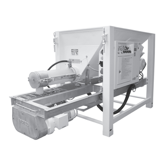
Page 14: Components
Chapter 4 Assembly and function 5. Unplug the motor (2) from the socket on the side of 4.4 Components the switching cabinet. Unlock the eccentric lock (3) that connects the motor to the material hopper and fold the motor away to the side (4). 6. -
Page 15: Frame With Pull-Out Frame For Pump Hopper, Material Hopper, Water Supply Button And Vibrator
400 V 3 PH! The small NOTE Make sure that the mixing shaft is con- silo inoCOMB Cabrio may only be operated with a permis- nected to the metering shaft. sible RCD type B residual current circuit breaker (30 mA). -
Page 16: Displays And Controls
Chapter 4 Assembly and function 4.5 Displays and controls 4.5.1 Switching cabinet NOTE Working with and without remote control. • When the remote control cable is plugged into the switching cabinet, the machine is switched on and off via the green push button at the end of the remote control cable. -
Page 17: Pump Unit (Pump Motor, Pump Shaft, Rotor/Stator And Mortar Pressure Gauge)
Chapter 4 Assembly and function 4.5.2 Pump unit (pump motor, pump shaft, rotor/sta- 4.5.3 Mixing unit (metering shaft and mixing tube tor and mortar pressure gauge) with mixing shaft) The pump shaft is connected to the pump motor via the The metering shaft (1) is connected to the mixer motor via drive shaft and rotates in the pump hopper during oper- the drive shaft and rotates in the metering hopper during... -
Page 18: Installing The Water Measuring System
Chapter 4 Assembly and function 4.6 Connections Sight glass Water quantity Solenoid valve 4.6.1 Power connections (230 / 400 V) Cleaning hose connection Water pressure switch The inlet pressure at the water metering system (min. 2.5 bar) is determined via a water pressure monitor (8). Below the minimum pressure (2.5 bar), the machine malfunctions and the illuminated button on the switching cabinet lights up. -
Page 19: Connections Of The Water Measuring System
Chapter 4 Assembly and function 4.6.2 Connections of the water measuring system Material loading of the small silo with big bags via two big bag boxes and the dry conveying unit inoFLEX Duo (low dust); room height min. 180 cm. Connection of the external water supply (1). - Page 20 Chapter 4 Assembly and function 4.8 Accessories The following accessories can be supplied for the small silo inoCOMB Cabrio. Set “D” Set “Ü1” Set “Ü2” Set “RS” Set “D”-Cabrio (Rotor/Stator D7-2.5 S) Item no. Ø 89 mm, 22 l/min, 40 bar, e.g., for spray applications 10043990 —...
- Page 21 Chapter 4 Assembly and function Set “D” Set “Ü1” Set “Ü2” Set “RS” Conveyor shaft for inoFLEX Duo Item no. • Delivery shaft for the inoFLEX Duo (L=3,200 mm) 10042457 Protective hose for delivery shaft inoFLEX Duo 10020118 • L = 1800 mm, incl. couplings, V part 3”, assembled Vibrator Item no.
- Page 22 Check valve set incl. GEKA coupling and 1 metre hose Item no. P P P P 10044163 Water barrel for inoCOMB Cabrio Item no. • incl. 2 m water hose between water barrel and booster pump with GEKA couplings P P P P 10042962 •...
- Page 23 Chapter 4 Assembly and function Set “D” Set “Ü1” Set “Ü2” Set “RS” Ø Length Item no. Water/air hose • For universal use, e.g. air, water 1/2” 10 m 10022000 • GEKA couplings crimped with sleeves on 1/2” 15 m 10022001 both sides Technical data:...
-
Page 24: Spare Parts And Diagrams
Chapter 4 Assembly and function 4.9 Spare parts and diagrams The spare parts for the small silo inoCOMB Cabrio are marked with numbers in the following pictures. The indi- vidual items are described in the table under the respective NOTE diagrams. -
Page 25: Drive Unit For The Mixer
Chapter 4 Assembly and function 4.9.2 Drive unit for the mixer Item Item no. Installation Name quantity 10041407 Units Worm gear motor 4 kW, 373 rpm 10006536 Units Three-phase motor 4 kW for mixer 10006139 Units Motor plate with bolt and seal 10006141 Units Sponge rubber square profile for mixer motor... -
Page 26: Pump Hopper
Chapter 4 Assembly and function 10004165 Units Rubber seal for mixer motor 10017172 Units Flange for rubber seal 10005048 Units Allen screw M 8 x 25 galvanised 10004699 Units Key 10 x 8 x 50 10004660 Units M shape detent edged washer, M8 10005050 Units Allen screw M 8 x 35 galvanised... -
Page 27: Drive Unit Incl. Chain Gear Box And Pump Hopper
Chapter 4 Assembly and function 4.9.4 Drive unit incl. chain gear box and pump hopper (Item no. 10043268) Drive unit incl. chain gear box and pump hopper Item Item no. Installation Name quantity 10006530 Units Spur gear motor 10044124 Units EMV screw connection 10043868 Units... -
Page 28: Drive Shaft In The Pump Hopper
Chapter 4 Assembly and function 4.9.5 Drive shaft in the pump hopper 10 11 12 13 14 Drive shaft in pump hopper Item Item no. Installation Name quantity 10041877 Units Drive shaft with Rotex coupling 10041878 Units Sprocket for Rotex coupling 10019580 Units Deep groove ball bearing 6309... -
Page 29: Water Measuring System
Chapter 4 Assembly and function 4.9.6 Water measuring system 13 14 Item Item no. Installation Name quantity 10043252 Water measuring system complete 10022372 Units GEKA coupling, 1/2” IT 10004149 Units GEKA seal 10006007 Units Brass sieve insert 10022412 Units Ball valve, 12”, with butterfly handle, IT/IT 10006493 Units T-piece, 1/2”, ET x 1/2”... -
Page 30: Switching Cabinet Inside (Level 1)
Chapter 4 Assembly and function 10006473 Units Reduction nipple 3/4" AG x 1/2" IG 10006471 Units Angular, 1/2”, 90°, galvanised, IT 10006470 Units Hose nozzle, 1/2” ET x 13 mm nozzle 10022443 Units Hose clamp, 1-ear, 19.2 - 21.8, (1/2”) 10021968 1.85 Meter... -
Page 31: Switching Cabinet Inside (Level 2)
Chapter 4 Assembly and function 4.9.8 Switching cabinet inside (Level 2) Item Item no. Installation Name quantity 10041075 Units Power contactor 10041448 Units Mains filter 4.9.9 Switching cabinet left and right side, underside Item Item no. Installation Name quantity Switching cabinet left side 10041077 Units Main switch... -
Page 32: Switching Cabinet Front
Chapter 4 Assembly and function Item Item no. Installation Name quantity Switching cabinet right side 10044250 Units Units Mounting socket for level probe 10015616 Units Mounted housing 10015398 Units Socket insert 4-pole Units Mounting box for protective grille 10015618 Units Attachment housing straight 10015610 Units... -
Page 33: Mixing Tube Inopowermix "S" Plus With Mixing Shaft And Mixing Tube Cover
Chapter 4 Assembly and function 10044145 Units Pushbutton black 10042981 Units Contact block closer 10044151 Units Sealing bonnet 10042983 Units 3-fold adapter Switch probe "ON / OFF” 10044089 Units Selector switch 10042981 Units Contact block shooter 10042983 Units 3-fold adapter Potentiometer 10016054 Units... -
Page 34: Mixing Tube Cover For Inopowermix "S" & "L" Mixing Tube (Art. No. 10044008)
Chapter 4 Assembly and function 4.9.12 Mixing tube cover for inoPOWERMIX “S” & “L” mixing tube (Art. No. 10044008) Mixing tube cover for inoPOWERMIX “S” & “L” mixing tube Item Item no. Installation Name quantity 10044008 Units Mixing tube cover for mixing tube inoPOWERMIX “L” 10006175 Units Plastic transfer for the mixing shaft... -
Page 35: Pump Shaft For Set "D" And "Ü
Chapter 4 Assembly and function 4.9.15 Pump shaft for set “D” and “Ü” Pump shaft for sets “D” and “Ü” Item Item no. Installation Name quantity 10041876 Units Pump shaft for sets “Ü1” and “Ü2” Ü50 coating with Rotex coupling (without sprocket) 10042437 Units... -
Page 36: Set "D
Chapter 4 Assembly and function 4.9.17 Set “D” 4.9.18 Set “Ü1” Item Item(s) Item (name) Quan- tity 10006096 Metering shaft pitch 30 mm 1 pcs. 10022515 Stator D7-2.5 “S” wf 1 pcs. Item Item(s) Item (name) Quan- tity 10022556 Rotor D7-2.5 “S”/ Plus 1 pcs. -
Page 37: Set "Ü2
Chapter 5 Transport and storage 4.9.19 Set “Ü2” 4.9.20 Set “RS” Item Item(s) Item (name) Quan- tity 10042444 Metering shaft pitch 45mm 1 pcs. 10041057 Suction flange R-pump / 1 pcs. Item Item(s) Item (name) Quan- R-jacket tity 10022887 Rotor R7-1.5 1 pcs. -
Page 38: Transport And Storage
5.1 Safety instructions for transport 3. Send one copy of the damage report to the transport company and another to Inotec GmbH. 4. And clarify the possible ways in which the damage could be remedied with one of our service centres (see... -
Page 39: Installation
When the motors are running, the metering shaft ro- • Install the small silo inoCOMB Cabrio only on level, hor- tates in the material hopper, the mixing shaft in the izontal ground. mixing tube and the pump shaft in the pump hopper. -
Page 40: Assembling The Pump Unit (Pump Shaft, Rotor, Stator And Pressure Gauge With Hose Coupling)
Chapter 6 Installation 6.2 Assembling the pump unit (pump shaft, rotor, sta- tor and pressure gauge with hose coupling) 1. Open the eccentric lock on the base frame below the water fitting. 2. Unlock the fixing bolt that secures the extendable pump hopper and pull out the pump hopper. -
Page 41: Installing The Water Measuring System
Chapter 6 Installation WARNING WARNING Acute Danger of injury! Water jet. The machine must not be operated without the guard Risk of injury and risk of property damage due to es- fixed in place. caping water. 1. Interrupt the external water supply by closing the water valve. -
Page 42: Regulation Of The Water Pressure
Chapter 6 Installation 6.5 Regulation of the water pressure 6. Use the potentiometer to set the speed and thus the A pressure reducer is installed and pre-set at the factory to desired delivery rate of the material transport. regulate the water pressure. The control cap on the pres- 7. -
Page 43: Starting The Machine
(e.g. respiratory protection) 7.2 Changing the material 1. Empty the material hopper and the pump hopper of the inoCOMB Cabrio small silo. 2. Then switch off the machine. 3. Close the valve on the external water supply. 4. Clean the material container, the metering shaft and the mixing tube with the mixing shaft. -
Page 44: Change Of Location On The Construction Site
8.1 Checking operating behaviour pump from the mains and water supply. 1. If you detect deviations in the operating behaviour, take the small silo inoCOMB Cabrio out of operation imme- diately. 2. Ensure that the damage and/or defects which led to the deviating operating behaviour are rectified. -
Page 45: Areas Of Application
Chapter 9 Areas of application 9 Areas of application 10 Cleaning & decommissioning All pumpable, powdered ready-mixed mortars can be pro- cessed with the inoCOMB Cabrio small silo. Always follow the manufacturer's instructions for the material! DANGER Electrical voltage. Danger of death due to electric shock. -
Page 46: Cleaning Process
Chapter 10 Cleaning & decommissioning Pushbutton “Reverse pump” • Use only conveyor hoses which are permissible with an operating pressure of 40 bar and a burst pressure of 120 8. Fill some more water into the pump hopper and start bar, and are in a technically perfect condition (e.g. -
Page 47: After Cleaning
Chapter 10 Cleaning & decommissioning 10004591) in order to make it easier to screw the rotor 25. Fold the motor back again and make sure that the me- into the stator. Make sure that the rotor is correctly in- tering shaft is connected to the motor via the motor stalled in the stator. -
Page 48: Decommissioning
Chapter 10 Cleaning & decommissioning 10.3 Decommissioning Running the machine until it is empty and switching it off DANGER 1. Stop the filling of the material hopper in time. Rotating mixing, metering and pump 2. Empty the material hopper, the pump hopper and the shafts. -
Page 49: Maintenance
Replace parts which are subject to wear as soon as the wear limits have been reached. Portable machines, like the inoCOMB Cabrio, must be subject to an annual elec- trical inspection according to the implementing regulation for electrical plant and operating resources (DGUV V3). This inspection may only be carried out by a qualified electrician (e.g. -
Page 50: Wear Limits
However, should a fault occur, please follow the replaced if necessary. instructions below on analysing, checking and remedying the fault or contact the Inotec Service team (see the address list for INOTEC service centres at the end of the document) 11.5.1 Metering shaft wear limit or call the INOTEC service hotline on: +49 7741 6805 777. - Page 51 Chapter 11 Maintenance Symptom Potential cause Check / solution Personnel qualification If the machine will not Power supply is • Check the power supply (power distribution points, socket, Machine start. cut off. power cable, cable reel). operator • Have the electrical control checked and have the fault rectified Service if necessary.
- Page 52 Chapter 11 Maintenance Symptom Potential cause Check / solution Personnel qualification Machine stops Material blockage in • Run the machine in reverse to reduce the mortar pressure. Machine (continued) the hose; pressure Check the mortar pressure on the mortar pressure gauge. If operator greater than 40 bar.
- Page 53 Chapter 11 Maintenance Symptom Potential cause Check / solution Personnel qualification Pump is delivering Material blockage in • In the event of a blockage, immediately switch off the ma- Machine the hose; pressure chine in order to prevent the blockage from becoming stuck operator no material;...
- Page 54 Chapter 11 Maintenance Symptom Potential cause Check / solution Personnel qualification Material too thick The amount of • Increase the flow volume by adjusting it on the needle valve Machine con- water supplied is too of the water fitting. operator sistency low;...
-
Page 55: Dismantling And Disposal
• Ensure there is enough space for disassembly. Your used INOTEC equipment will be taken back by us and • Wear gloves and safety boots to avoid injuries. disposed of in an environmentally conscious manner. Please •... -
Page 56: Systems
EC Directive 2006/42/EC. This declaration will become void in the event of any modification made to the machine without our approval. Designation of the unit: inoCOMB Cabrio Machine model: Small silo... -
Page 57: General Terms Of Business Of The Company Inotec Gmbh
In the case of simple negligence on the part of INOTEC GmbH, this is a fixed amount totalling 0.5% for each full week of the IV. The customer hereby assigns to INOTEC GmbH the purchase price, wages... -
Page 58: Feeding And Earthing
Chapter 13 Systems 13.3 Feeding and earthing Page 58... -
Page 59: Circuit Diagram: Load Circuits 01
Chapter 13 Systems 13.3.1 Circuit diagram: Load circuits 01 Page 59... -
Page 60: Circuit Diagram: Load Circuits 02
Chapter 13 Systems 13.3.2 Circuit diagram: Load circuits 02 Page 60... -
Page 61: Circuit Diagram: Direction Of Rotation Changeover
Chapter 13 Systems 13.3.3 Circuit diagram: Direction of rotation changeover Page 61... -
Page 62: Circuit Diagram: Contactor Control
Chapter 13 Systems 13.3.4 Circuit diagram: Contactor control Page 62... -
Page 63: Circuit Diagram: Sensors
Chapter 13 Systems 13.3.5 Circuit diagram: Sensors Page 63... -
Page 64: Circuit Diagram: Operating Switch
Chapter 13 Systems 13.3.6 Circuit diagram: Operating switch Page 64... -
Page 65: Circuit Diagram: Pump
Chapter 13 Systems 13.3.7 Circuit diagram: Pump Page 65... -
Page 66: Circuit Diagram: Nano 01
Chapter 13 Systems 13.3.8 Circuit diagram: Nano 01 Page 66... -
Page 67: Circuit Diagram: Nano 02
Chapter 13 Systems 13.3.9 Circuit diagram: Nano 02 Page 67... -
Page 68: Circuit Diagram: Nano 03
Chapter 13 Systems 13.3.10 Circuit diagram: Nano 03 Page 68... -
Page 69: Circuit Diagram: Nano 04
Chapter 13 Systems 13.3.11 Circuit diagram: Nano 04 Page 69... -
Page 70: Order Form
Chapter 14 Order form 14 Order form Fax to: +49(0)7741-6805-665 Delivery address Invoice to Name of customer Consultant Date Number Item no. Item name Our General Terms of Business, Delivery and Payment apply. The customer has been made aware of these terms and agrees to the application of the same. -
Page 71: Index
Cleaning & decommissioning .........45 Cleaning process ............46 Safety ................7 Commissioning .............43 Safety instructions for transport ........38 Complaints ..............38 Scope of delivery inoCOMB Cabrio ........12 Components ..............14 Sequence of assembly ............13 Connections ..............18 Spare parts and diagrams ..........24 Storage ................38 Switching cabinet ............16 Damage report ..............38... -
Page 72: Locations
16 Locations Your sales partner (English language) INOTEC GmbH (Headquarter) Daimlerstraße 9-11 79761 Waldshut-Tiengen Germany Phone +49 7741 / 6805 675 +49 7741 / 6805 665 E-Mail: j.tetling@inotec-gmbh.com Wherever you are, we’re there, too. - Page 73 Accessories & Waste water Tillage Compressed air / air dehumidifiers spare parts systems compressors / high-pressure cleaners Power tools / electrical appliances INOTEC GmbH • Daimlerstraße 9-11 • D-79761 Waldshut-Tiengen • Tel.: +49 77 41 / 68 05-0 • www.inotec-gmbh.com...
Need help?
Do you have a question about the inoCOMB Cabrio and is the answer not in the manual?
Questions and answers