Sign In
Upload
Manuals
Brands
Innovative Integration Manuals
I/O Systems
X5-210M
Innovative Integration X5-210M Manuals
Manuals and User Guides for Innovative Integration X5-210M. We have
1
Innovative Integration X5-210M manual available for free PDF download: User Manual
Innovative Integration X5-210M User Manual (115 pages)
Brand:
Innovative Integration
| Category:
I/O Systems
| Size: 3 MB
Table of Contents
Table of Contents
3
Real Time Solutions
9
Introduction
9
Vocabulary
9
What Is X5-210M
10
What Is Malibu
10
What Is C++ Builder
10
What Is Dialogblocks
10
What Is Wxwidgets
11
What Is Microsoft MSVC
11
What Kinds of Applications Are Possible with Innovative Integration Hardware
11
Why Do I Need to Use Malibu with My Baseboard
11
Finding Detailed Information on Malibu
12
Online Help
12
Innovative Integration Technical Support
12
Innovative Integration Web Site
12
Typographic Conventions
13
Windows Installation
14
Host Hardware Requirements
14
Software Installation
14
Starting the Installation
15
The Installer Program
15
Figure 1. Vista Verificaton Dialog
15
Figure 2. Innovative Install Program
16
Tools Registration
17
Figure 3. Progress Is Shown for each Section
17
Bus Master Memory Reservation Applet
18
Figure 4. Toolset Registration Form
18
Figure 5. Busmaster Configuration
18
Figure 6. Installation Complete
19
Hardware Installation
19
After Power-Up
19
Installation on Linux
21
Package File Names
21
Prerequisites for Installation
21
The Redistribution Package Group - Malibured
21
Malibu
22
Other Software
22
Baseboard Package Installation Procedure
22
Board Packages
23
Unpacking the Package
23
Creating Symbolic Links
24
Applets
24
Completing the Board Install
24
Documentation
24
Examples
24
Hardware
25
Linux Directory Structure
24
Table 1. X5 XMC Bus Requirements
26
Hardware Installation
26
Compatible Host Cards
26
Figure 7. Innovative Single Lane Pcie - XMC.3 Adapter Card (P/N 80172)
27
Figure 8. Innovative PCI 64/66 - XMC.3 (4X Lanes) Adapter Card (P/N 80167-0)
27
Figure 9. Innovative X8 Lane PCI Express - XMC.3 (8X Lanes) Adapter Card (P/N 80173-0)
28
Figure 10. Einstrument Node - Cabled PCI Express Adapter (X1 Lane) for XMC Modules (II P/N 90181)
28
Figure 11. Einstrument PC - Embedded PC (Windows/Linux) Hosts Two XMC Modules (II P/N 90199)
28
System Requirements
29
Power Considerations
29
Table 2. Required Pcie Resource Allocations
29
Mechanical Considerations
30
Table 3. XMC Mounting Hardware
30
About the X5 XMC Modules
31
X5 XMC Architecture
31
Figure 12. X5 XMC Family Block Diagram
31
Table 4. X5 XMC Family
32
Table 5. X5 XMC Family Peripherals
32
X5 Computing Core
32
Table 6. X5 Computing Core Devices
33
Alert Log
33
X5 PCI Express Interface
34
Table 7. PCI Express Standards Compliance
34
Table 8. Interfaces from PCI Express to Application Logic
34
Data Buffering and Memory Use
35
Computational SRAM
35
Data Buffer DRAM
35
Serial EEPROM Interface
35
Eeprom
35
Digital I/O
36
Software Support
37
Table 9. Iusesdioport Class Operations
37
Digital IO Electrical Characteristics
38
Figure 13. DIO Control Register (Bar1+0X14)
38
Figure 14. Digital IO Port Addresses
38
Notes on Digital IO Use
39
Table 10. Digital IO Bits Electrical Characteristics
39
P16 Serdes I/O
39
Figure 15. Virtex-5 Rocket I/O Assignments for P16 Signals
41
Thermal Protection and Monitoring
41
Thermal Failures
42
Led Indicators
42
Table 11. X5 JTAG Scan Path
43
Framework Logic
43
Integrating with Host Cards and Systems
44
Figure 16. XMC Eeprom Programmer
45
Updating the XMC Logic Configuration EEPROM
45
Table 12. Development Tools for the Windows Snap Example
47
The Snap Example
47
Tools Required
47
Program Design
48
Writing Custom Applications
47
Configure Tab
48
User Interface
48
Setup Tab
49
Host Side Program Organization
50
Stream Tab
50
Applicationio
51
Initialization
51
Starting Data Flow
54
Handle Data Available
57
Eeprom Access
59
The Host Application
48
The Applicationio Class
61
User Interface
61
Configure Tab
62
Setup Tab
63
The Linux Snap Example
61
The Wave Example
64
Stream Tab
64
Stream Initialization
64
Data Required Event Handler
67
The Wave Example for Linux
68
The Applicationio Class
68
User Interface
68
Developing Host Applications
70
Borland Turbo C
70
Other Considerations
71
Dialogblocks
74
Summary
74
Applets
75
Common Applets
75
Registration Utility (Newuser.exe)
75
Reserve Memory Applet (Reservememdsp.exe)
75
Data Analysis Applets
76
Binary File Viewer Utility (Binview.exe)
76
Applets for the X5-210M Baseboard
77
Logic Update Utility (Vsprom.exe)
77
Finder
78
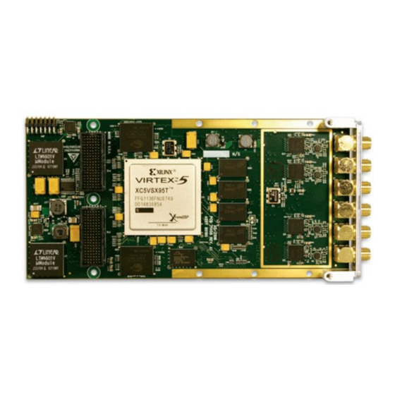
Figure 17. X5-210M Module
79
X5-210M XMC Module
79
Introduction
79
Figure 18. X5-210M Block Diagram
80
Hardware Features
80
A/D Converters
80
Table 13. X5-210M A/D Features
81
A/D Front End
81
Figure 1. X5-210M A/D Channel 0 Front End
82
Input Range and Conversion Codes
82
Table 1. A/D Conversion Coding
83
Driving the A/D Inputs
83
Overrange Detection
83
Sample Rate Generation and Clocking Controls
83
Table 1. Input Clock Electrical Specifications
84
Table 2. Clock Oscillator Electrical Specifications
84
Triggering
84
Figure 1. Analog Triggering Timing
85
Table 3. Table 1: Trigger Modes
85
Trigger Source
85
Decimation
86
Framed Trigger Mode
86
Framework Logic Functionality
86
Figure 2. X5-210M Framework Logic Data Flow
87
Power Controls and Thermal Design
87
System Thermal Design
88
Temperature Sensor and over Temperature Protection
88
Table 1. Alert Types
89
Table 2. Alert Packet Format
90
Software Support
90
Table 1. X5-210M Power Consumption
93
Table 2. X5-210M Environmental Limits
94
Table 3. X5-210M Analog Performance Summary
94
Analog Input
94
Figure 1. Frequency Response for 1 Mhz to 1 Ghz Span, 500 Mvp-P Input
96
Figure 2. Frequency Response for 1 Mhz to 1 Ghz Span, 500 Mvp-P Input
96
Figure 3. X5-210M Ground Noise, Fs = 249 MSPS, Input Grounded
97
Figure 4. X5-210M Noise Floor, Fs = 249 MSPS, Input Grounded
98
Figure 5. Signal Quality: Fs = 249 Mhz Fin = 5 Mhz 85%FS
99
Figure 6. Signal Quality: Fs = 249 Mhz, Fin = 70 Mhz 85%FS
100
Figure 8. Signal Quality Vs Input Frequency, Fin = 5 Mhz, 85%FS
102
Figure 9. Signal Quality Vs Input Frequency, Fin = 70 Mhz, 85%FS
103
Table 1. Connectors J1-J6 Functions
105
Figure 1. P15 XMC Connector Orientation
106
Table 1. X5-210M XMC Connector P15 Pinout
108
Table 2. P15 Signal Descriptions
108
Figure 1. P16 XMC Connector Orientation
110
Table 1. X5-210M XMC Secondary Connector P16 Pinout
111
Table 2. P16 Signal Descriptions
112
Table 1. X5-210M JP3 Xilinx JTAG Connector Pinout
113
Figure 1. X5-210M JP1 Orientation, Board Face View
113
Figure 2. X5-210M JP1 Orientation, Board Top Edge View
113
Figure 1. X5-210M Mechanicals (Top View) Rev B
114
Figure 2. X5-210M Mechanicals (Bottom View) Rev B
115
Advertisement
Advertisement
Related Products
Innovative Integration Categories
Motherboard
I/O Systems
More Innovative Integration Manuals
Login
Sign In
OR
Sign in with Facebook
Sign in with Google
Upload manual
Upload from disk
Upload from URL