Table of Contents
Advertisement
Quick Links
Advertisement
Table of Contents

Summary of Contents for Innovative Integration X5-210M
- Page 1 X5-210M User's Manual...
- Page 2 X5-210M User's Manual X5-210M User's Manual The X5-210M User's Manual was prepared by the technical staff of Innovative Integration on February 5, 2009. For further assistance contact: Innovative Integration 2390-A Ward Ave Simi Valley, California 93065 (805) 578-4260 FAX: (805) 578-4225 email: techsprt@innovative-dsp.com...
-
Page 3: Table Of Contents
What is C++ Builder?............................10 What is DialogBlocks?............................10 What is wxWidgets?.............................11 What is Microsoft MSVC?...........................11 What kinds of applications are possible with Innovative Integration hardware?..........11 Why do I need to use Malibu with my Baseboard?....................11 Finding detailed information on Malibu.......................12 Online Help..................................12 Innovative Integration Technical Support........................12... - Page 4 Table of Contents X5-210M User's Manual System Requirements................................29 Power Considerations................................29 Mechanical Considerations..............................30 About the X5 XMC Modules..............................31 X5 XMC Architecture.................................31 X5 Computing Core................................32 X5 PCI Express Interface..............................34 Data Buffering and Memory Use............................35 Computational SRAM............................35 Data Buffer DRAM..............................35 Serial EEPROM Interface..............................35 EEPROM................................35...
- Page 5 Summary....................................19 Applets....................................20 Common Applets.................................20 Registration Utility (NewUser.exe)..........................20 Reserve Memory Applet (ReserveMemDsp.exe)......................20 Data Analysis Applets................................21 Binary File Viewer Utility (BinView.exe)........................21 Applets for the X5-210M Baseboard..........................22 Logic Update Utility (VsProm.exe)..........................22 Finder....................................23 X5-210M XMC Module...............................24 Introduction..................................24 Hardware Features................................25 A/D Converters................................25 A/D Front End..................................26 Input Range and Conversion Codes..........................27...
-
Page 6: X5-210M User's Manual
Table of Contents X5-210M User's Manual Environmental..................................38 Analog Input..................................39 Connectors....................................49 RF Connectors J1-J6................................49 XMC P15 Connector................................50 XMC P16 Connector................................54 Xilinx JTAG Connector..............................57 Mechanicals..................................58 X5-210M User's Manual... - Page 7 Table 1. Connectors J1-J6 Functions.............................50 Table 1. X5-210M XMC Connector P15 Pinout........................53 Table 2. P15 Signal Descriptions............................53 Table 1. X5-210M XMC Secondary Connector P16 Pinout....................56 Table 2. P16 Signal Descriptions............................57 Table 1. X5-210M JP3 Xilinx JTAG Connector Pinout......................58 X5-210M User's Manual...
- Page 8 Figure 1. Frequency Response for 1 MHz to 1 GHz span, 500 mVp-p input...............41 Figure 2. Frequency Response for 1 MHz to 1 GHz span, 500 mVp-p input...............41 Figure 3. X5-210M Ground Noise, Fs = 249 MSPS, input grounded...................42 Figure 4. X5-210M Noise Floor, Fs = 249 MSPS, input grounded..................43 Figure 5.
-
Page 9: Introduction
Introduction Real Time Solutions! Thank you for choosing Innovative Integration, we appreciate your business! Since 1988, Innovative Integration has grown to become one of the world's leading suppliers of DSP and data acquisition solutions. Innovative offers a product portfolio unrivaled in its depth and its range of performance and I/O capabilities . -
Page 10: What Is X5-210M
What is Malibu? Malibu is the Innovative Integration-authored component suite, which combines with the Borland, Microsoft or GNU C++ compilers and IDEs to support programming of Innovative hardware products under Windows and Linux. Malibu supports both high-speed data streaming plus asynchronous mailbox communications between the DSP and the Host PC, plus a wealth of Host functions to visualize and post-process data received from or to be sent to the target DSP. -
Page 11: What Is Wxwidgets
DC to RF frequency applications, video or audio processing. Additionally, multiple Innovative Integration baseboards can be used for a large channel or mixed requirement systems and data acquisition cards from Innovative can be integrated with Innovative's other DSP or data acquisition baseboards for high- performance signal processing. -
Page 12: Finding Detailed Information On Malibu
Also, feel free to register and browse our product forums at http://forum.iidsp.com/, which are an excellent source of FAQs and information submitted by Innovative employees and customers. Innovative Integration Web Site Additional information on Innovative Integration hardware and the Malibu Toolset is available via the Innovative Integration website at www.innovative-dsp.com X5-210M User's Manual... -
Page 13: Typographic Conventions
Table of Contents X5-210M User's Manual Typographic Conventions This manual uses the typefaces described below to indicate special text. Typeface Meaning Text in this style represents text as it appears onscreen or in code. It Source Listing also represents anything you must type. -
Page 14: Windows Installation
If these items are not installed prior to running the Innovative Integration install, the installation program will not permit installation of the associated development libraries. However, drivers and DLLs may be installed to facilitate field deployment. -
Page 15: Starting The Installation
Table of Contents X5-210M User's Manual Starting the Installation To begin the installation, start Windows. Shut down all running programs and disable anti-virus software. Insert the installation DVD. If Autostart is enabled on your system, the install program will launch. If the DVD does not Autostart, click on Enter the path to the Setup.bat program located at the root of your DVD-ROM drive (i.e. -
Page 16: Figure 2. Innovative Install Program
Table of Contents X5-210M User's Manual Figure 2. Innovative Install Program Using this interface, specify which product to install, and where on your system to install it. 1) Select the appropriate product from the Product Menu. 2) Specify the path where the development package files are to be installed. You may type a path or click “Change” to browse for, or create, a directory. -
Page 17: Tools Registration
Table of Contents X5-210M User's Manual The installation will display a progress window, similar to the one shown below, for each item checked. Figure 3. Progress is shown for each section. Tools Registration At the end of the installation process you will be prompted to register. If you decide that you would like to register at a later time, click “Register Later”. -
Page 18: Bus Master Memory Reservation Applet
It is recommend that you completely fill out this form and return it to Innovative Integration, via email or fax. Upon receipt, Innovative Integration will provide access codes to enable technical support and unrestricted access to applets. -
Page 19: Hardware Installation
Table of Contents X5-210M User's Manual Figure 6. Installation complete Click the “Shutdown Now” button to shut down your computer. Once the shutdown process is complete unplug the system power cord from the power outlet and proceed to the next section, “Hardware Installation.”... -
Page 20: X5-210M User's Manual
Table of Contents X5-210M User's Manual Innovative Integration boards are plug and play compliant, allowing Windows to detect them and auto-configure at start-up. Under rare circumstances, Windows will fail to auto-install the device-drivers for the JTAG and baseboards. If this happens, please refer to the “TroubleShooting”... -
Page 21: Installation On Linux
Table of Contents X5-210M User's Manual Installation on Linux This chapter contains instruction on the installation of the baseboard software for Linux operating systems. Software installation on Linux is performed by loading a number of packages. A Package is a special kind of archive file that contains not only the files that are to be installed, but also installation scripts and dependency information to allow a smooth fit into the system. -
Page 22: Malibu
Table of Contents X5-210M User's Manual intel-ipp_rti-5.3p.x32.rpm Installs Intel IPP library redistributable files. The installation CD, or the web site contains a file called LinuxNotes.pdf giving instructions on how to load these packages and how to install the drivers onto your Linux machine. This file is also loaded onto the target machine by the the Malibu- LinuxRed RPM. -
Page 23: Board Packages
Table of Contents X5-210M User's Manual Each of these packages automatically extract files into the folder, herein referred to as the Innovative /usr/Innovative root folder in the text that follows. For example, the X5-400 RPM extracts into /usr/Innovative/X5-400-[ver] symbolic link named... -
Page 24: Creating Symbolic Links
Table of Contents X5-210M User's Manual Creating Symbolic Links The example programs assume that the user has created symbolic links for the installed board packages. A script file is provided to simplify this operation by the Malibu Red package. In the MalibuRed/KerPlug directory, there is a script called quicklink. -
Page 25: Hardware
Table of Contents X5-210M User's Manual Hardware This directory contains files associated with programming the board Logic and any logic images provided. X5-210M User's Manual... -
Page 26: Compatible Host Cards
Table of Contents X5-210M User's Manual Hardware Installation The X5 XMC cards may be used on a variety of host cards supporting an XMC.3 PCI Express (VITA standard 42.3 compatible) site. XMC P16 is also used for system integration including use as a dedicated data channel. -
Page 27: Figure 7. Innovative Single Lane Pcie - Xmc.3 Adapter Card (P/N 80172)
Table of Contents X5-210M User's Manual Figure 7. Innovative Single lane PCIe – XMC.3 adapter card (P/N 80172) Figure 8. Innovative PCI 64/66 – XMC.3 (4x lanes) adapter card (P/N 80167-0) X5-210M User's Manual... -
Page 28: Figure 9. Innovative X8 Lane Pci Express - Xmc.3 (8X Lanes) Adapter Card (P/N 80173-0)
Table of Contents X5-210M User's Manual Figure 9. Innovative x8 Lane PCI Express – XMC.3 (8x lanes) adapter card (P/N 80173-0) Figure 10. eInstrument Node – cabled PCI Express adapter (x1 lane) for XMC Modules (II P/N 90181) Figure 11. eInstrument PC – embedded PC (Windows/Linux) hosts two XMC modules (II P/N 90199) -
Page 29: System Requirements
Table of Contents X5-210M User's Manual XMC systems should be be compatible with VITA 42.3 specification for P15. The P16 interface can only be used when the PCI Express interface is present and active. The XMC P16 interface to the host may be customized in the Application Logic. -
Page 30: Mechanical Considerations
Table of Contents X5-210M User's Manual The X5 XMCs are designed to operate over the typical commercial temperature range of 0 to 70 C, but this relies on sufficient forced air cooling for most installations and modules. At the lower temperatures, it is also required that the environment be non-condensing for the standard commercial modules. -
Page 31: About The X5 Xmc Modules
Table of Contents X5-210M User's Manual About the X5 XMC Modules Chapter 1. In this chapter, we will discuss the common features of the X5 module family. Specifics on each module are covered in later chapters. X5 XMC Architecture The X5 XMC modules share a common architecture and many features such as the PCI Express interface, data buffering features, the Application Logic, and other system integration features. -
Page 32: X5 Computing Core
Table of Contents X5-210M User's Manual Table 4. X5 XMC Family X5 XMC Features Applications X5-400M 2 A/D channels, 14 bit, 400MHz; 2 D/A channels, up to Software radio, RADAR, medical imaging 500M updates/sec X5-210M 4 A/D channels, 14 bit, 250 MHz... -
Page 33: Alert Log
Table of Contents X5-210M User's Manual (4Gbits in a x64 configuration), and two banks of QDR2 SRAM (32Mbits total in two x32 dual-ported banks). The FPGA uses the memories for data buffering and computational workspace. Table 6. X5 Computing Core Devices... -
Page 34: X5 Pci Express Interface
Table of Contents X5-210M User's Manual X5 PCI Express Interface The X5 module family has a PCI Express interface that provides a lane, 2.5 Gbps full duplex link to the host computer. The interface is compatible with industry standard PCI Express systems and may be used in a variety of host computers. The following standards govern the PCI Express interface on the X5 XMC modules. -
Page 35: Data Buffering And Memory Use
Table of Contents X5-210M User's Manual Data Buffering and Memory Use There are two sets of memory devices attached to the application FPGA that provide data buffering and computational RAM for FPGA applications. Computational SRAM The SRAM on the X5 series is a 4Mbyte memory dedicated as FPGA local memory. Applications in the FPGA may use the SRAM as a local buffer memory if the data buffer is too large to fit in FPGA block RAMs, or as memory for an embedded processor in the FPGA. -
Page 36: Digital I/O
Table of Contents X5-210M User's Manual The I2C bus is slow and the calibration is read out of the EEPROM at initialization time by the application software and written into registers in the application logic for real-time error correction. The EEPROM also has a write cycle limit of 100K cycles, so it should only be written to when calibration is performed or configuration information changes. -
Page 37: Software Support
Table of Contents X5-210M User's Manual The DIO port is presented on P16. See the connectors section of this chapter the connector pin out and information about the connector. Software Support The digital I/O hardware is controlled by the class. Its properties: IUsesDioPort Table 9. -
Page 38: Digital Io Electrical Characteristics
Table of Contents X5-210M User's Manual Function 31..6 Figure 13. DIO Control Register (BAR1+0x14) Port Address DIO_L BAR1+0x13 DIO_H BAR1+0x16 Figure 14. Digital IO Port Addresses Data may be written to/read from the digital I/O port using the digital I/O port data registers. Data written to ports bits which are set for output mode will be latched and driven to the corresponding port pins, while data written to input bits will be ignored. -
Page 39: Notes On Digital Io Use
Table of Contents X5-210M User's Manual Parameter Value Notes Output Current +/-12mA FPGA can be reconfigured for custom designs for other drive currents. Input Logic '1' >= 2VDC Thresholds '0' < 0.8VDC Input Impedance >1M ohm || 15 pF Excludes cabling Table 10. - Page 40 Table of Contents X5-210M User's Manual P16 Signal Virtex-5 FG1136 Pin Number Virtex-5 MGT Signal Identifier RXP0 MGT_124_RXN1 RXN0 MGT_124_RXP1 TXP1 MGT_124_ TXN0 TXN1 MGT_124_TXP0 RXP1 MGT_124_RXN0 RXN1 MGT_124_RXP0 TXP2 MGT_120_ TXN1 TXN2 MGT_120_TXP1 RXP2 MGT_120_RXN1 RXN2 MGT_124_RXP1 TXP3 MGT_120_ TXN0...
-
Page 41: Thermal Protection And Monitoring
Table of Contents X5-210M User's Manual P16 Signal Virtex-5 FG1136 Pin Number Virtex-5 MGT Signal Identifier RXP7 MGT_126_RXN0 RXN7 MGT_126_RXP0 Figure 15. Virtex-5 Rocket I/O assignments for P16 signals Note that the positive and negative polarities of the individual lanes are reversed between the polarity notation on the P16 connector versus the polarity notation on the Rocket I/O pin pairs. -
Page 42: Thermal Failures
Table of Contents X5-210M User's Manual // Read/write current warning temperature float t = Module.LogicWarningTemperature(); Module.LogicWarningTemperature(70.0); // Read current failure temperature float t = Module.LogicFailureTemperature(); // See if the module is in thermal shutdown bool state = Module.Failed(); Thermal Failures The X5 modules will shut down if the Virtex-5 die temperature exceeds 85 degrees Celsius. -
Page 43: Framework Logic
Table of Contents X5-210M User's Manual Custom logic designs can use it for any purpose. When using the stock firmware, the state of user logic LEDs can be controlled using the property. Innovative::X5_400M::Led() JTAG Scan Path X5 modules have a JTAG scan path for the Xilinx devices on the module. This is used for logic development tools such as Xilinx ChipScope and System Generator, and for initial programming of the PCI FPGA configuration FLASH ROM. -
Page 44: Integrating With Host Cards And Systems
Table of Contents X5-210M User's Manual Integrating with Host Cards and Systems The X5 XMCs may be directly integrated PCI Express systems that support VITA 42.3 XMC modules. The host card must be both mechanically and electrically compatible or an adapter card must be used. -
Page 45: Updating The Xmc Logic Configuration Eeprom
Table of Contents X5-210M User's Manual Updating the XMC logic Configuration EEPROM Virtex-5 configuration data is stored in an onboard flash EEPROM which may be updated using software provided by Innovative. Logic images may come as updates from Innovative, or be generated by a user developing custom functionality. - Page 46 Table of Contents X5-210M User's Manual module on the PCIE bus. Once this is accomplished, a known-good image may be reprogrammed into the EEPROM using the VsProm.exe tool. X5-210M User's Manual...
-
Page 47: Writing Custom Applications
Table of Contents X5-210M User's Manual Writing Custom Applications Most scientific and engineering applications require the acquisition and storage of data for analysis after the fact. Even in cases where most data analysis is done in place, there is usually a requirement that some data be saved to monitor the system. -
Page 48: Program Design
Table of Contents X5-210M User's Manual On the host side, the Malibu library is provided in source form, plus pre-compiled Microsoft, Borland or GCC libraries. The application code that implements the entirety of the board-specific functionality of example is factored into the unit. -
Page 49: Setup Tab
Table of Contents X5-210M User's Manual device from those present in the system. All X5 family devices of whatever type share a sequence of target number identifiers. The first board found is Target 0, the second Target 1, and so on. -
Page 50: Stream Tab
Table of Contents X5-210M User's Manual The module supports a test mode for module debugging and system test. The Test Counter Enable is used to turn on test mode and substitutes a ramp signal with channel number in the upper byte of the data. The Decimation section sets up the decimation logic to discard data, reducing the incoming data rate. -
Page 51: Applicationio
Table of Contents X5-210M User's Manual The predefined IUserInterface interface class is defined in ApplicationIo.h. The constructor of ApplicationIo requires a pointer to the interface, which is saved and used to perform the actual updates to the UI inside of ApplicationIo's methods. - Page 52 Table of Contents X5-210M User's Manual Configure Module Event Handlers Module.OnBeforeStreamStart.SetEvent(this, &ApplicationIo::HandleBeforeStreamStart); Module.OnBeforeStreamStart.Synchronize(); Module.OnAfterStreamStart.SetEvent(this, &ApplicationIo::HandleAfterStreamStart); Module.OnAfterStreamStart.Synchronize(); Module.OnAfterStreamStop.SetEvent(this, &ApplicationIo::HandleAfterStreamStop); Module.OnAfterStreamStop.Synchronize(); Similarly, HandleBeforeStreamStart, HandleAfterStreamStart and HandleAfterStreamStop handle events issued on before stream start, after stream start and after stream stop respectively. These handlers could be designed to perform multiple tasks as event occurs including displaying messages for user.
- Page 53 Table of Contents X5-210M User's Manual handler in the main UI thread context. This results in a slight performance penalty, but allows us to call UI methods in the event handler freely. The Timer uses a similar synchronization method, Thunk(). Here the event is called in the main thread context, but the issuing thread does not wait for the event to be handled before proceeding.
-
Page 54: Starting Data Flow
Table of Contents X5-210M User's Manual //--------------------------------------------------------------------------- void ApplicationIo::Close() Stream.Disconnect(); StreamConnected = false; Opened = false; UI->Status("Stream Disconnected..."); Starting Data flow After downloading interface logic user can setup clocking and triggering options. The stream button then can be used to start streaming and thus data flow. - Page 55 Table of Contents X5-210M User's Manual return; The module supports both framed and continuous triggering. In framed mode, each trigger event, whether external or software initiated, results in the acquisition of a fixed number of samples. In continuous mode, data flow continues whenever the trigger is active, and pauses while the trigger is inactive.
- Page 56 Table of Contents X5-210M User's Manual notification on each acquired frame. In other applications, such as when an FFT is embedded within the FPGA, the packet size can be programmed to match the processing block size from the algorithm within the FPGA.
-
Page 57: Handle Data Available
Table of Contents X5-210M User's Manual enum IUsesX5Alerts::AlertType Alert[] = { IUsesX5Alerts::alertTimeStampRollover, IUsesX5Alerts::alertSoftware, IUsesX5Alerts::alertWarningTemperature, IUsesX5Alerts::alertInputFifoOverrun, IUsesX5Alerts::alertInputTrigger, IUsesX5Alerts::alertInputOverrange }; for (unsigned int i = 0; i < Settings.AlertEnable.size(); ++i) Module.Alerts().AlertEnable(Alert[i], Settings.AlertEnable[i] ? true : false); The fragment above enables alert generation by the module. The GUI control includes check boxes for each of the types of alerts of which the module is capable. - Page 58 Table of Contents X5-210M User's Manual When the event is signaled, the data buffer must be copied from the system bus-master pool into an application buffer. The preceding code copies the packet into the local Buffer called Packet. Since data sent from the hardware can be of arbitrary type (integers, floats, or even a mix, depending on the board and the source), Buffer objects have no assumed data type and have no functions to access the data in them.
-
Page 59: Eeprom Access
Table of Contents X5-210M User's Manual Stop streaming when both Channels have passed their limit if (Settings.AutoStop && IsDataLoggingCompleted() && !Stopped) // Stop counter and display it double elapsed = Clock.Stop(); StopStreaming(); UI->AfterStreamAutoStop(); UI->Log("Stream Mode Stopped automatically"); UI->Log(std::string("Elasped (S): ") + FloatToString(elapsed));... - Page 60 Table of Contents X5-210M User's Manual void ApplicationIo::ReadRom() Module.IdRom().LoadFromRom(); Settings.ModuleName = Module.IdRom().Name(); Settings.ModuleRevision = Module.IdRom().Revision(); for (int ch = 0; ch < Channels(); ++ch) Settings.AdcGain[ch] = Module.Input().Gain(ch); Settings.AdcOffset[ch] = Module.Input().Offset(ch); Settings.Calibrated = Module.Input().Calibrated(); There is also a mechanism to write to the on-board EEPROM.
-
Page 61: The Linux Snap Example
Table of Contents X5-210M User's Manual AdcCoefGrid[0, i]->Value = gcnew String("NAN"); if (!_isnan(Io->Settings.AdcOffset[i]) && _finite(Io->Settings.AdcOffset[i])) AdcCoefGrid[1, i]->Value = gcnew String( Innovative::FloatToString(Io->Settings.AdcOffset[i], 4).c_str()); else AdcCoefGrid[1, i]->Value = gcnew String("NAN"); PllCorrectionEdit->Text = gcnew String( Innovative::FloatToString(Io->Settings.PllCorrection, 4).c_str()); CalibratedCheckBox->Checked = Io->Settings.Calibrated; ModuleNameEdit->Text = gcnew String(Io->Settings.ModuleName.c_str());... -
Page 62: Configure Tab
Table of Contents X5-210M User's Manual Configure Tab As soon as the application is launched, the Configure tab is displayed. In this tab, a combo box is available to allow the selection of the device from those present in the system. All X5 family devices of whatever type share a sequence of target number identifiers. -
Page 63: Setup Tab
Table of Contents X5-210M User's Manual Setup Tab This tab has a set of controls that hold the parameters for transmission. These settings are delivered to the target and configure the target accordingly. This tab has several sections. The Clock section offers configurations and routing of the clock. -
Page 64: The Wave Example
Table of Contents X5-210M User's Manual Stream Tab The two buttons in the button bar start and stop data streaming. Press the running man button to start streaming data. Press the stop button to stop streaming, unless the stream has stopped itself. - Page 65 Table of Contents X5-210M User's Manual // ApplicationIo::StartStreaming() //--------------------------------------------------------------------------- void ApplicationIo::StartStreaming() if (!FStreamConnected) UI->Log("Stream not connected! -- Open the boards"); return; // Make sure packets fit nicely in BM region. if (FBmSizeWords/8 < (unsigned int)Settings.StreamPacketSize) UI->Log("Error: Packet size is larger than recommended size");...
- Page 66 Table of Contents X5-210M User's Manual FStreaming = true; // Set Decimation Factor int factor = Settings.DecimationEnable ? Settings.DecimationFactor : 0; Module.Output().Decimation(factor); // All channels trigger together Module->Output().ExternalTrigger((Settings.ExternalTrigger == 1)); // Frame count in units of packet elements if (Settings.Framed) Module->Output().Framed(Settings.FrameCount);...
-
Page 67: Data Required Event Handler
Table of Contents X5-210M User's Manual Data Required Event Handler When the output stream needs additional data, the Data Required event is signalled. The Wave application uses this call to generate new blocks for each channel and send them to the output via the SendOneBlock() method. -
Page 68: The Wave Example For Linux
Table of Contents X5-210M User's Manual The Wave Example for Linux With the release of Linux support for Malibu and for Innovative products, there are versions of the example programs for this platform. This section discusses the Linux Wave example. - Page 69 Table of Contents X5-210M User's Manual X5-210M User's Manual...
-
Page 70: Developing Host Applications
Table of Contents X5-210M User's Manual Developing Host Applications Developing an application will more than likely involve using an integrated development environment (IDE) , also known as an integrated design environment or an integrated debugging environment. This is a type of computer software that assists computer programmers in developing software. -
Page 71: Other Considerations
Table of Contents X5-210M User's Manual Error: First chance exception at $xxxxxxxx. Exception class EAccessViolation with message “Access Violation!” Process ???.exe (nnnn) Other considerations: Project Options ++ Compiler (bcc32) Output Settings check – Specify output directory for object files(-n) (release build) Release... - Page 72 Table of Contents X5-210M User's Manual Microsoft Visual Studio 2005 Microsoft Visual C++ 2005 (version 8) Project Properties When creating a new application with File, New, Project with Widows Forms Application: X5-210M User's Manual...
- Page 73 Table of Contents X5-210M User's Manual Project Properties (Alt+F7) Configuration Properties General Additional Include Directories Malibu PlotLab/Include – for graph/scope display Code Generation Run Time Library Multi-threaded Debug DLL (/Mdd) Precompiled Headers Create/Use Precompile Headers Not Using Precompiled Headers Linker...
-
Page 74: Dialogblocks
Table of Contents X5-210M User's Manual DialogBlocks DialogBLocks Project Settings (under Linux) Project Options [Configurations] Compiler name = GCC Build mode = Debug Unicode mode = ANSI Shared mode = Static Modularity = Modular GUI mode = GUI Toolkit = <your choice wxX11, wxGTK+2, etc>... -
Page 75: Applets
Table of Contents X5-210M User's Manual Applets The software release for a baseboard contains programs in addition to the example projects. These are collectively called “applets”. They provide a variety of services ranging from post analysis of acquired data to loading programs and logic to a full replacement host user interface. -
Page 76: Data Analysis Applets
Table of Contents X5-210M User's Manual Each Innovative PCI-based DSP baseboard requires 2 to 8 MB of memory to be reserved for its use, depending on the rates of bus-master transfer traffic which each baseboard will generate. Applications operating at transfer rates in excess of 20 MB/sec should reserve additional, contiguous busmaster memory to ensure gap-free data acquisition. -
Page 77: Applets For The X5-210M Baseboard
Table of Contents X5-210M User's Manual Applets for the X5-210M Baseboard Logic Update Utility (VsProm.exe) The Logic Update Utility applet is designed to allow field- upgrades of the logic firmware on the 210M module. The utility permits an embedded firmware logic update file to reprogrammed into the baseboard Flash ROM, which stores the "personality"... -
Page 78: Finder
Table of Contents X5-210M User's Manual Finder The Finder is designed to help correlate board target numbers against PCI slot numbers in systems employing multiple boards. Target Number Select the Target number of the board you wish to identify using the Target Number combo box. -
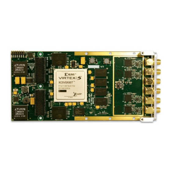
Page 79: Figure 17. X5-210M Module
X5-210M XMC Module Introduction The X5-210M is a member of the X5 XMC family that has four channels of 14-bit 250 MHz A/D conversion with DC coupled inputs. A high performance computing core for signal processing, data buffering and system IO is built around a Virtex-5 FPGA. -
Page 80: Figure 18. X5-210M Block Diagram
Hardware Features A/D Converters The X5-210M has four channels of 14-bit A/D sampling at up to 250 MSPS using Texas Instruments ADS6149 converters. Minimum sample rate is 1 MHz, and the X5-210M implements a DC-coupled 50 ohm terminated SMA connector-based front end. -
Page 81: Table 13. X5-210M A/D Features
Non-volatile EEPROM coefficient memory. Table 13. X5-210M A/D Features Conversion clocking is provided by either a low jitter fixed on board oscillator or an external clock input. The clock buffering is designed to minimize jitter and maximum acquired signal quality. See the clock discussion for more details. -
Page 82: Figure 1. X5-210M A/D Channel 0 Front End
Table of Contents X5-210M User's Manual Figure 1. X5-210M A/D Channel 0 Front End Input bandwidth measurement is shown in the data section of this chapter. Input Range and Conversion Codes Each A/D input has a +1V to -1V single-ended input with 50 ohm input impedance. Other input ranges may be custom ordered. -
Page 83: Table 1. A/D Conversion Coding
Conversion clock sources on the X5-210M include an external clock input and provision for an on-board oscillator. Clocks used to drive the X5-210M must be extremely low jitter in order to yield good signal to noise ratio, noise floor, and spur performance. -
Page 84: Table 1. Input Clock Electrical Specifications
Triggering The X5-210M has a trigger control component in the FPGA that controls the data acquisition process. The sample clock specifies the instant in time when data is sampled, whereas triggering specifies when data is kept. This allows the application to collect data at the desired rate, and keep only the data that is required. -
Page 85: Table 3. Table 1: Trigger Modes
Table of Contents X5-210M User's Manual Trigger Mode Data Collected/Played Back Start Trigger Stop Trigger Continuous All enabled channel pairs Software or rising edge of Software or falling edge of external trigger external trigger Framed N sample points for each of... -
Page 86: Framed Trigger Mode
The FrameWork Logic implements a data flow for the X5-210M that supports standard data acquisition functionality. This data flow, when used with the supporting software, allows the X5-210M to act as a data acquisition card with 512MB of data buffering and high speed data streaming to the host PCI Express. The example software for the X5-210M demonstrates data flow control, logic loading and data logging. -
Page 87: Figure 2. X5-210M Framework Logic Data Flow
The Board Basics and Host Communications chapters of this manual discuss the use of the packet data system used on the X5 module family. The X5-210M module FrameWork Logic connects the data from A/D interface to the packet system by forming the data into 32-bit words of consecutive enabled channels. -
Page 88: System Thermal Design
System Thermal Design The X5-210M can dissipate upwards of 25 watts depending on the features in use and details of the logic design, such as amount and rate of data processing. Forced air cooling may be required depending on the power dissipation and the ambient operating temperatures. -
Page 89: Table 1. Alert Types
Table of Contents X5-210M User's Manual quality. Monitoring functions can be created in custom logic that triggers only when the digitized data shows that something interesting happened. Alerts make this type of application easier for the host to implement since they don't require host activity until the event occurs. -
Page 90: Table 2. Alert Packet Format
Table of Contents X5-210M User's Manual Dword # Description Header 1: PDN & Total #, N, of Dwords in packet ( e.g. Headers + data payload ) Header 2: 0x00000000 Alerts Signaled Timestamp Software Word 10..6 X"1303000" & "000" & mq_overflow(0);... - Page 91 Where to start? The best place to start with the X5-210M module is to install the module and use the SNAP example to acquire some data. This program lets you log data from the module and use all the features like triggering, clocks, alerts and calibration ROM.
- Page 92 X5-210M User's Manual Calibration Each X5-210M is calibrated as part of the production tests performed. The calibration results are provided on the production test report with each module. The results of the calibration are stored in the on-board EEPROM memory. These calibration values are used by the logic to correct the analog errors and are loaded into the A/D as part of the initialization by the software.
-
Page 93: Table 1. X5-210M Power Consumption
Performance Data Power Consumption The X5-210M requires the following power for typical operation with when using the FrameWork Logic. This typical number assumes a 250 MHz system clock rate and 125 MSPS A/D data rates for the application logic. Table 1. X5-210M Power Consumption... -
Page 94: Table 2. X5-210M Environmental Limits
2.2 Analog Input A summary of the analog performance follows for the X5-210M module. All tests performed at room temperature, with no forced air cooling unless noted. Test environment was PCIe adapter card in PC running testbed software using FrameWork Logic. - Page 95 Table of Contents X5-210M User's Manual Test Group Parameter Measured Units Test Conditions Analog Input Crosstalk Worst case, Fin = 70 MHz, 2V p-p input Analog Input Amplitude 0 to 150 MHz, 500 mVp-p sine Variation X5-210M User's Manual...
-
Page 96: Figure 1. Frequency Response For 1 Mhz To 1 Ghz Span, 500 Mvp-P Input
Table of Contents X5-210M User's Manual X5-210M Analog Input Bandwidth X5-210M Analog Input Bandwidth A/D delta A/D delta (dB normal- (dB normal- ized to ized to 5MHz) C1 = 5MHz) C1 = 6.8pF 6.8pF 1000 Fin (MHz) Fin (MHz) Figure 1. Frequency Response for 1 MHz to 1 GHz Figure 2. -
Page 97: Figure 3. X5-210M Ground Noise, Fs = 249 Msps, Input Grounded
Table of Contents X5-210M User's Manual Figure 3. X5-210M Ground Noise, Fs = 249 MSPS, input grounded X5-210M User's Manual... -
Page 98: Figure 4. X5-210M Noise Floor, Fs = 249 Msps, Input Grounded
Table of Contents X5-210M User's Manual Figure 4. X5-210M Noise Floor, Fs = 249 MSPS, input grounded X5-210M User's Manual... -
Page 99: Figure 5. Signal Quality: Fs = 249 Mhz Fin = 5 Mhz 85%Fs
Table of Contents X5-210M User's Manual Figure 5. Signal quality: Fs = 249 MHz Fin = 5 MHz 85%FS X5-210M User's Manual... -
Page 100: Figure 6. Signal Quality: Fs = 249 Mhz, Fin = 70 Mhz 85%Fs
Table of Contents X5-210M User's Manual Figure 6. Signal quality: Fs = 249 MHz, Fin = 70 MHz 85%FS X5-210M User's Manual... - Page 101 Table of Contents X5-210M User's Manual Signal Quality vs Input Amplitude S/N (dB) SINAD (dB) SFDR (dB) Input Amplitude (Vp-p) Channel Amplitude (Vp- SINAD SFDR ENOB (bits) (dB) (dB) (dB) 41.7 41.5 53.2 0.0260 55.9 55.7 69.3 0.0055 62.6 62.2 87.3...
-
Page 102: Figure 8. Signal Quality Vs Input Frequency, Fin = 5 Mhz, 85%Fs
Table of Contents X5-210M User's Manual Signal Quality versus Sample Rate 0.015 0.013 0.011 0.009 0.007 SNR (dB) 0.005 THD (%) SFDR (dB) 0.003 0.001 -0.001 Sample Rate (MHz) Channel Fs (MHz) SNR (dB) SFDR (dB) SINAD (dB) ENOB (bits) 66.4... -
Page 103: Figure 9. Signal Quality Vs Input Frequency, Fin = 70 Mhz, 85%Fs
Table of Contents X5-210M User's Manual Signal Quality versus Sample Rate 0.1000 0.0900 0.0800 0.0700 0.0600 SNR (dB) 0.0500 SFDR (dB) THD (%) 0.0400 0.0300 0.0200 0.0100 Sample Rate (MHz) Channel Fs (MHz) SNR (dB) SFDR (dB) SINAD (dB) ENOB (bits) 52.3... - Page 104 Table of Contents X5-210M User's Manual Connectors RF Connectors J1-J6 J1-J6connectors are positioned on the front panel and allow input, output, clock and trigger signals to be connected to the module. Connector Type: SMA 50 ohm Number of Connections: 1 per signal...
-
Page 105: Table 1. Connectors J1-J6 Functions
Table of Contents X5-210M User's Manual Connector Function A/D channel 0 A/D channel 1 Trigger input Clock input A/D channel 2 A/D channel 3 Table 1. Connectors J1-J6 Functions XMC P15 Connector P15 is the XMC PCI Express connector to the host. -
Page 106: Figure 1. P15 Xmc Connector Orientation
Table of Contents X5-210M User's Manual Figure 1. P15 XMC Connector Orientation X5-210M User's Manual... - Page 107 Table of Contents X5-210M User's Manual Column PET0p0 PET0n0 3.3V PET0p1 PET0n1 VPWR MRSTI# PET0p2 PET0n2 3.3V PET0p3 PET0n3 VPWR MRSTO# PET0p4 PET0n4 3.3V PET0p5 PET0n5 VPWR +12V X5-210M User's Manual...
-
Page 108: Table 1. X5-210M Xmc Connector P15 Pinout
ROOT# FAN** Table 1. X5-210M XMC Connector P15 Pinout Note: All unlabeled pins are not used by X5 modules but may defined in VITA42 and VITA42.3 specifications. **Note:LED_N and FAN are special purpose pins that support Innovative adapter card functions. These are reserved pins on the VITA42.3 specification. - Page 109 Table of Contents X5-210M User's Manual Signal Description PET0nx PCI Express Tx +/- PET0px/ PER0nx PCI Express Rx +/- PER0px/ PEX REFCLK+/- PCI Express reference clock, 100 MHz +/- MRSTI# Master Reset Input, active low MRSTO# Master Reset Output, active low...
-
Page 110: Figure 1. P16 Xmc Connector Orientation
Table of Contents X5-210M User's Manual Figure 1. P16 XMC Connector Orientation X5-210M User's Manual... -
Page 111: Table 1. X5-210M Xmc Secondary Connector P16 Pinout
Table of Contents X5-210M User's Manual Table 1. X5-210M XMC Secondary Connector P16 Pinout Column TXP0 TXN0 TXP1 TXN1 DGND DGND DIO0 DGND DGND DIO1 TXP2 TXN2 TXP3 TXN3 DGND DGND DIO2 DGND DGND DIO3 TXP4 TXN4 TXP5 TXN5 DGND... -
Page 112: Table 2. P16 Signal Descriptions
Table of Contents X5-210M User's Manual Table 2. P16 Signal Descriptions Signal Description Digital IO 0-15 DIO0 TXP0-7 SERDES transmit positive TXN0-7 SERDES transmit negative SERDES receive positive RXP0-7 SERDES receive negative RXN0-7 Xilinx JTAG Connector JP1 is used for the Xilinx JTAG chain. It connects directly with Xilinx JTAG cables such as Parallel Cable IV or Platform USB. -
Page 113: Table 1. X5-210M Jp3 Xilinx Jtag Connector Pinout
Mechanicals The following diagrams show the X5-210M connectors and physical locations. The XMC conforms to IEEE 1386 form factor, 75mm x 150mm. The spacing to the host card is 10 mm and consumes a single slot in desktop and Compact PCI/PXI chassis. -
Page 114: Figure 1. X5-210M Mechanicals (Top View) Rev B
Table of Contents X5-210M User's Manual Figure 1. X5-210M Mechanicals (Top View) Rev B X5-210M User's Manual... -
Page 115: Figure 2. X5-210M Mechanicals (Bottom View) Rev B
Table of Contents X5-210M User's Manual Figure 2. X5-210M Mechanicals (Bottom View) Rev B X5-210M User's Manual...
Need help?
Do you have a question about the X5-210M and is the answer not in the manual?
Questions and answers