Sign In
Upload
Manuals
Brands
Innotech Manuals
Controller
MAXIM I
User Manuals: Innotech MAXIM I Digital Controller
Manuals and User Guides for Innotech MAXIM I Digital Controller. We have
1
Innotech MAXIM I Digital Controller manual available for free PDF download: Installation Instructions Manual
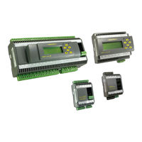
Innotech MAXIM I Installation Instructions Manual (60 pages)
MAXIM Series
Brand:
Innotech
| Category:
Controller
| Size: 5 MB
Table of Contents
Table of Contents
5
Chapter 1 - Preliminary Information
9
Scope
10
1-1.1 Systems Covered by this Manual
10
1-1.2 Terminology Used in this Manual
11
1-1.3 Document Layout
11
Overview of MAXIM Series Controllers
12
1-2.1 Primary Network Controllers
12
Table 1-2: Features of MAXIM Series Controllers
12
1-2.2 Sub System Network Controllers
13
1-2.3 Sub System Gateway (IG01)
13
Special Considerations
14
Tools and Materials
14
1-2.4 MAXIM I Controller
14
Chapter 2 - Mechanical Installation
15
Overview
16
Figure 2-1: Typical Enclosure Installation
16
Physical Description and Dimension Diagrams
17
2-2.1 Overview
17
2-2.2 MAXIM I, II, III, and 1010 Controllers
17
Figure 2-2: MAXIM I and MAXIM II Controller Dimensions
17
2-2.3 Minimax, Micromax, Vavmax, and IG01
18
Figure 2-3: MAXIM III and MAXIM 1010 Controller Dimensions
18
Figure 2-4: Minimax, Micromax, Vavmax and IG01 Controller Dimensions
19
General Installation Information
20
2-3.1 Overview
20
2-3.2 General Installation Guidelines
20
Figure 2-5: LCD Optimum Viewing Angle
20
2-3.3 Installing on DIN Rail
21
Figure 2-6: DIN Rail Dimensions
21
Figure 2-7: Installing MAXIM Controller on a DIN Rail
21
Chapter 3 - Electrical Installation
23
Overview
24
Electrical Installation Practices
24
MAXIM Controller Wiring
24
Figure 3-1: MAXIM Series III Connection Details Generated with Maxcon Software
25
3-3.1 MAXIM I, II, III, and 1010 Controllers
26
Figure 3-2: MAXIM I Controller Terminal Connection Layout
26
Figure 3-3: MAXIM II Controller Terminal Connection Layout
26
Figure 3-4: MAXIM III Controller Terminal Connection Layout
27
Figure 3-5: MAXIM 1010 Controller Terminal Connection Layout
27
Figure 3-6: Analogue Output Driving Multiple Solid State Relays
30
Table 3-4: MAXIM 1010 Universal Outputs
31
3-3.2 Minimax Controllers (MM01 / MM02)
32
Figure 3-7: Minimax (MM01 & MM02) Controller Terminal Connection Layout
32
Table 3-5: Minimax Power Source Specifications
32
3-3.3 Vavmax and Micromax Controllers
34
Figure 3-8: Vavmax and Micromax Controller Terminal Connection Layout
34
Table 3-10: Vavmax and Micromax Power Terminals
35
Table 3-9: Vavmax and Micromax Power Source Specifications
35
3-3.4 IG01 Sub System Gateway
38
Figure 3-9: IG01 Sub System Gateway Terminal Connection Layout
38
Table 3-14: IG01 Sub System Gateway Power Terminals
39
Chapter 4 - Network Installation
41
Overview
42
Figure 4-1: Innotech Network Diagram
42
Chapter 5 - Commissioning
43
Overview
44
Inspect the Installation
44
Figure 5-1: Checking Power Input Voltage
46
Figure 5-2: Checking Universal Inputs for 0V
47
Figure 5-3: Checking Digital Relay Output Wiring
48
Figure 5-4: Checking Analogue Output Voltage
50
Figure 5-5: Checking Analogue Output Resistance
51
Figure 5-6: End of Cable Jumper Locations on Sub Network Devices
52
Appendix A - Using the CT01 Commissioning Tool
53
Overview
54
Connecting to Subsystem Network Devices
54
A-2.1 Connecting Directly to Controller on Sub System Network
54
Figure A-1: Connecting the CT01 to a Sub System Network Device
54
A-2.2 Connecting to Sub System Gateway (IG01)
55
Figure A-2: Connecting the CT01 to a Sub System Gateway IG01
55
A-2.3 Connecting to Sub System Network
56
Figure A-3: Connecting the CT01 to a Sub Network Device
56
A-2.4 CT01 Menus and Navigation
57
Logging Onto the Controller
57
Figure A-4: CT01 Interface - Navigation and Menus
57
Vavmax Settings
58
Commissioning
58
A-5.2 Configuring the K-Factor
59
A-5.1 Calibration of Sensors
59
Customer Assistance
60
Innotech Support
60
Advertisement
Advertisement
Related Products
Innotech MAXIM II
Innotech MAXIM 1010
Innotech MAXIM III
Innotech MM01
Innotech MM02
Innotech MOBI
Innotech MFS-TRA-54-Z Series
Innotech MFS-TRA-55-Z Series
Innotech MFS-TRA-54-Z01
Innotech MFS-NET-81
Innotech Categories
Safety Equipment
Controller
Remote Control
Security Sensors
Racks & Stands
More Innotech Manuals
Login
Sign In
OR
Sign in with Facebook
Sign in with Google
Upload manual
Upload from disk
Upload from URL