Sign In
Upload
Manuals
Brands
Infratek Manuals
Measuring Instruments
108B
User Manuals: Infratek 108B Power Analyzer
Manuals and User Guides for Infratek 108B Power Analyzer. We have
1
Infratek 108B Power Analyzer manual available for free PDF download: Abridged User Manual
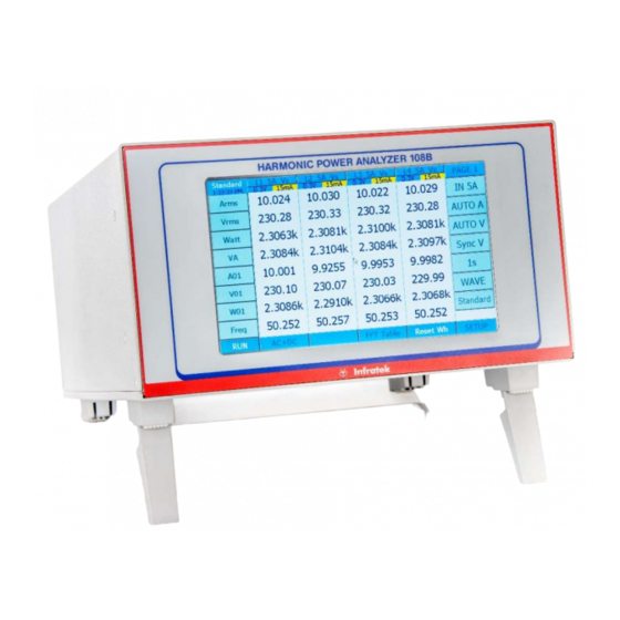
Infratek 108B Abridged User Manual (76 pages)
SINGLE- TO FOUR PHASE INFRATEK POWER ANALYZER
Brand:
Infratek
| Category:
Measuring Instruments
| Size: 4 MB
Table of Contents
Table of Contents
2
1 Power Analyzer Features, Quick Overview, Safety
5
Standard Measure Mode
6
Logging Measure Mode
7
Transient Measure Mode
7
Power-Speed Measure Mode (Option)
8
Power Analyzer Rear Panel
9
Summary of 108B Power Analyzer Features
10
Safety Instructions
11
2 Connection to Circuits
12
Measurement in 3-Phase Mains Circuit
12
Three Wattmeter Connection
12
Aron Connection
13
108 B Mathematical Definitions and Specifications
14
Mathematical Definitions
14
Specifications
18
4 Operating the Power Analyzer from the Front Panel
22
Operations in Standard Measure Mode
23
Selecting Measure Mode
23
Selecting Current Inputs Using same Inputs for All Phases
24
Selecting Individual Current Inputs Per Phase
24
Selecting Current Range Using same Range for All Phases
25
Selecting Voltage Range Using same Range for All Phases
25
Selecting Measurement Synchronization (Synchronization for All Phases)
26
Selecting Averaging Time
26
Selecting Display
26
Selecting Wave Forms (Graph)
27
Selecting FFT Table and FFT Bar Graph
27
Selecting AC or DC+AC-Coupling
27
Selecting Display RUN and Display HOLD
28
Resetting Energy
28
Selecting Display Quantities
28
Selecting SETUP
31
Operations in Logging Measure Mode
34
Valid Synchronization
34
Selecting CYCLES
34
What Has to be Observed When Using Logging
35
Operations in Transient Measure Mode
36
What Is Measured in Transient Measure Mode
36
Two Ways to Use Transient Measure Mode
36
Basics of Power-Speed Measure Mode (Option)
38
What Is Measured in Power-Speed Measure Mode
38
Operations in Power-Speed Measure Mode
38
5 Operating the Power Analyzer Using a Computer Interface
41
What Has to be Observed When Using an Interface
41
What Has to be Observed When Using the Interface Command Set
41
Computer Interface Command Set
44
Composite Commands
44
Reading Voltages Reading and Writing Voltage Scale Factors
45
Reading Currents Reading and Writing Current Scale Factor
46
Reading Power, Apparent Power, and Reactive Power
47
Reading Energy, Charge, and Time
47
Reading Frequency, Impedance, and Phase Angle
48
Reading/Writing Range of Harmonics, Number Phases for Output, and Cycle for Logging
48
Read and Write Display, RS232 Baud Rate, IEEE-488 Address
49
Read and Write Common Control Commands
49
6 Computer Operating Software
51
Installing Computer Operating Software
51
108A Data Window (Computer Software)
52
Select Interface
52
Select Instrument Mode
53
Select Software Mode
54
Operate the Computer Software
54
Input, Ranges, Synchronization, Aperture Selection
55
Phase Slider for Selecting Individual Settings Per Phase
55
Curve
55
FFT Numerics (Harmonics)
56
FFT Bar Graph (Harmonics)
56
Vector Graph (Phase Angle)
56
IEC Data Window
57
Control / Setting Window
59
Logging-, Transient-, Power Speed Measure Mode
61
7 Analog Input and -Output
62
Analog Input and Output Specification
63
Programming the Analog Outputs
63
Using Inputs for Motor Testing (See also 4.1 Motor Testing)
64
Using Low Current Shunt for Standby Power Measurement
65
8 Data Management
66
Operating the Power Analyzer Using the USB Interface
66
Operating the Power Analyzer Using the Ethernet Interface
66
Measurement Data from the Power Analyzer (USB) to Computer
67
9 Calibration Via 108B Front Panel
68
Equipment Needed
68
Calibration Procedure
68
Voltage Calibration at 60Hz
68
Current Calibration at 60Hz, Shunt Input Calibration
69
Storing the Calibration Constants
70
A few Practical Hints
70
108B Calibration Using Windows Operating Software (Labview)
71
Equipment Needed
71
Calibration Procedure
71
Voltage Calibration at 60Hz
71
Current Calibration at 60Hz (in 5A)
72
Current Calibration at 60Hz (in 1A)
73
Current Calibration at 60Hz (in 30A)
74
Current Calibration at 60Hz (SHUNT)
74
Storing the Calibration Constants
75
A few Practical Hints
75
Advertisement
Advertisement
Related Products
Infratek 106A
Infratek 101A
Infratek 31
Infratek SM201
Infratek Categories
Measuring Instruments
Test Equipment
More Infratek Manuals
Login
Sign In
OR
Sign in with Facebook
Sign in with Google
Upload manual
Upload from disk
Upload from URL