Sign In
Upload
Manuals
Brands
Infinera Manuals
Multi-service Platforms
ATN
Infinera ATN Manuals
Manuals and User Guides for Infinera ATN. We have
1
Infinera ATN manual available for free PDF download: Hardware Description Manual
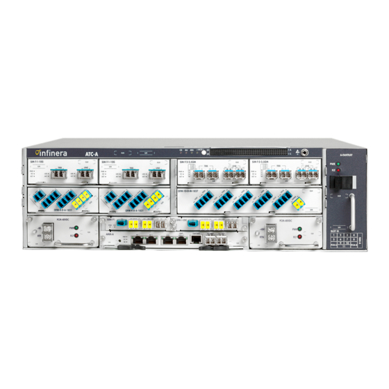
Infinera ATN Hardware Description Manual (176 pages)
Brand:
Infinera
| Category:
Multi-service Platforms
| Size: 3 MB
Table of Contents
Table of Contents
3
About this Document
15
Objective
15
Audience
15
Document Organization
16
List of Acronyms
16
Documents for Release 1.0
17
Technical Assistance
18
Documentation Feedback
18
Chapter 1 - Introduction
20
Infinera Digital Optical Network
20
Infinera ATN
20
Figure 1-1 Infinera Digital Optical Network
20
Infinera Dispersion Management Chassis
21
Infinera DTN
21
Infinera Optical Line Amplifier
21
Release 1.0 Feature Summary
22
Chapter 2 - Infinera ATN
22
Infinera Corporation ATN Hardware Description Guide Release
28
ATC System Specifications
30
ATC Power Consumption
30
Table 2-1 ATC Power Consumption Numbers
30
ATC Compliancy
31
Table 2-2 ATC Hardware Compliancy
31
ATC Technical Specifications
32
Table 2-3 ATC Technical Specifications
32
ATC Overview
33
Front View
33
Table 2-4 ATC Common Components
33
Table 2-5 ATC Supported Circuit Packs
33
Figure 2-1 ATC-A Front View
34
Figure 2-2 ATC -P Front View
34
ATC Thermal Loading
35
Table 2-6 ATC Typical Heat Release (19-Inch Frame)
35
Table 2-7 ATC Maximum Heat Release (19-Inch Frame)
36
Table 2-8 ATC Typical Heat Release (23-Inch Frame)
37
Table 2-9 ATC Maximum Heat Release (23-Inch Frame)
39
ATC Product Details
41
Functional Description
41
Table 2-10 ATC Product Details
41
Mechanical Specifications
42
Table 2-11 ATC-A Mechanical Specifications
42
Figure 2-3 ATC-A Dimensions
43
Table 2-12 ATC-P Mechanical Specifications
43
Rack Mounting Ears
44
Power Conversion Module (PCM)
44
Figure 2-4 ATC-P Dimensions
44
Table 2-13 ATN Power Conversion Module
44
DC Power Conversion Module (PCM-48VDC)
45
External Indicators
45
Figure 2-5 ATC PCM-48VDC Faceplate
45
Connectors
46
Power Leds
46
Table 2-14 ATC PCM-48VDC Visual Alarm Indicators
46
Figure 2-6 ATC Power Distribution Diagram
47
Power Distribution Architecture
47
Table 2-15 ATC PCM-48VDC Technical Specifications
47
Technical Specifications
47
Alarm Panel
48
Chassis-Level Alarm Leds
48
Figure 2-7 ATC-A Alarm Panel Front View
48
Table 2-16 ATC-A Visual Alarm Indicators - Chassis Level
48
Alarm Cutoff (ACO) Indicators
49
External Connectors
49
Figure 2-8 ATC Alarm Input/Output Contacts
49
Table 2-17 ATC-A Audio Alarm Indicators - Chassis Level
49
Alarm Input Contact Pin Assignments
50
Table 2-18 ATC External Connectors
50
Table 2-19 ATC Alarm Relay Contact Specifications
50
Table 2-20 ATC Alarm Input Contact Pin Assignments
50
Technical Specifications
50
Alarm Output Contact Pin Assignments
51
Table 2-21 ATC Alarm Output Contact Pin Assignments
51
Fan Tray
54
Figure 2-9 Fan Tray
54
Table 2-22 ATC Fan Tray Visual Alarm Indicators
54
Technical Specifications
55
Air Filter
55
Mechanical Specifications
55
Table 2-23 ATC Fan Tray Technical Specifications
55
Table 2-24 ATC Air Filter Mechanical Specifications
55
Fiber Management Guide and Cable Guides
56
Figure 2-10 Fan Tray with Air Filter
56
Table 2-25 Fiber and Cable Components
56
Fiber Management Guide
57
Figure 2-11 ATN with Fiber and Cable Guides
57
Cable Management Guides
58
Figure 2-12 ATN Fiber Guide Assembly
58
Card Cage
59
ATC-A Card Cage
59
Figure 2-13 ATN Cable Guide Assemblies
59
ATC-P Card Cage
60
Figure 2-14 ATC-A Card Cage
60
Table 2-26 ATC-A Chassis Slot Assignments
60
Figure 2-15 ATC-P Card Cage
61
Table 2-27 ATC-P Chassis Slot Assignments
61
ATN Management Module (AMM)
62
Functional Description
62
Table 2-28 AMM-A Product Details
62
Table 2-29 AMM-A Parameters
62
Block Diagram
63
Figure 2-16 AMM-A Functional Block Diagram
63
External Indicators and Connectors
64
Circuit Pack Level Leds
64
Figure 2-17 AMM-A Faceplate
64
Table 2-30 AMM-A Status LED Indicators
64
Connectors
65
Port Indicators
65
Technical Specifications
65
Table 2-31 AMM-A Connectors
65
Table 2-32 AMM-A Port Indicators
65
Table 2-33 AMM-A Technical Specifications
66
ATN Amplifier Module (AAM)
67
Functional Description
67
Block Diagram
67
Table 2-34 AAM Product Details
67
External Indicators and Connectors
68
Figure 2-18 AAM-B1 Functional Block Diagram
68
Figure 2-19 AAM-P1 Functional Block Diagram
68
Circuit Pack Level Leds
69
Connectors
69
Figure 2-20 AAM-B1 Faceplate
69
Figure 2-21 AAM-P1 Faceplate
69
Table 2-35 AAM Status LED Indicators
69
Table 2-36 AAM-B1 and AAM-P1 Connectors
69
Technical Specifications
70
Optical Specifications
70
Table 2-37 AAM-B1 and AAM-P1 Technical Specifications
70
Table 2-38 AAM-B1 and AAM-P1 Optical Specifications
70
Optical Filter Modules (OFM)
71
Table 2-39 OFM Product Details
71
10-Channel DWDM Ofms
73
Functional Description
73
Block Diagram
74
Figure 2-22 OFM-10-D-M-5059 Functional Block Diagram
74
Figure 2-23 OFM-10-D-M-4049 Functional Block Diagram
74
Figure 2-24 OFM-10-D-M-2837 Functional Block Diagram
75
Figure 2-25 OFM-10-D-M-1827 Functional Block Diagram
75
External Connectors
76
Figure 2-26 OFM-10-D-M-5059 Faceplate
76
Figure 2-27 OFM-10-D-M-4049 Faceplate
76
Connectors
77
Figure 2-28 OFM-10-D-M-2837 Faceplate
77
Figure 2-29 OFM-10-D-M-1827 Faceplate
77
Table 2-40 OFM-10-D-M-5059 Connectors
77
Table 2-41 OFM-10-D-M-4049 Connectors
79
Table 2-42 OFM-10-D-M-2837 Connectors
80
Table 2-43 OFM-10-D-M-1827 Connectors
82
Table 2-44 10-Channel DWDM OFM Technical Specifications
83
Technical Specifications
83
Optical Specifications
84
Table 2-45 10-Channel DWDM OFM Optical Specifications
84
Cascaded 10-Channel DWDM Optical Filter Modules
85
Figure 2-30 Cascaded 10-Channel DWDM Ofms
86
4-Channel DWDM Ofms
87
Block Diagram
87
Functional Description
87
Figure 2-31 4-Channel DWDM OFM Functional Block Diagram
88
Connectors
89
External Connectors
89
Figure 2-32 4-Channel OFM: OFM-4-D-A-5659 Faceplate
89
Table 2-46 4-Channel DWDM OFM Connectors
89
Table 2-47 4-Channel DWDM OFM Technical Specifications
94
Technical Specifications
94
Optical Specifications
95
Table 2-48 4-Channel DWDM OFM Optical Specifications
95
8-Channel CWDM OFM
96
Block Diagram
96
Functional Description
96
Connectors
97
External Connectors
97
Figure 2-33 8-Channel OFM-8-C-M-4761 Functional Block Diagram
97
Figure 2-34 OFM-8-C-M-4761 Faceplate
97
Table 2-49 8-Channel OFM-8-C-M-4761 Connectors
97
Optical Specifications
99
Table 2-50 8-Channel CWDM OFM-8-C-M-4761 Technical Specifications
99
Table 2-51 OFM-8-C-M-4761 Optical Specifications
99
Technical Specifications
99
2-Channel CWDM Ofms
100
Block Diagram
100
Figure 2-35 2-Channel CWDM OFM Functional Block Diagram
100
Functional Description
100
Connectors
101
External Connectors
101
Figure 2-36 2-Channel CWDM OFM Faceplate
101
Table 2-52 2-Channel CWDM OFM Connectors
101
Table 2-53 2-Channel CWDM OFM Technical Specifications
102
Technical Specifications
102
Optical Specifications
103
Table 2-54 2-Channel CWDM OFM Optical Specifications
103
Passive OSC Add/Drop Module
104
Block Diagram
104
External Indicators and Connectors
104
Figure 2-37 OFM-1-OSC Functional Block Diagram
104
Connectors
105
Technical Specifications
105
Figure 2-38 OFM-1-OSC Faceplate
105
Table 2-55 OFM-1-OSC Connectors
105
Table 2-56 OFM-1-OSC Technical Specifications
105
Optical Specifications
106
Table 2-57 OFM-1-OSC Optical Specifications
106
Service Interface Module (SIM)
107
SIM Module 10G (SIM-T-1-10G)
107
Functional Description
107
Table 2-58 SIM Product Details
107
Block Diagram
108
Figure 2-39 SIM-T-1-10G Functional Block Diagram
108
Circuit Pack Level Leds
109
External Indicators and Connectors
109
Figure 2-40 SIM-T-1-10G Faceplate
109
Port Level Leds
109
Table 2-59 SIM-T-1-10G Status LED Indicators
109
Table 2-60 SIM-T-1-10G Status Indicators
109
Interface Specifications
110
Table 2-62 SIM-T-1-10G Interface Specifications
110
SIM Module 2.5G (SIM-T-2-2.5GM)
111
Block Diagram
111
Figure 2-41 SIM-T-2-2.5GM Functional Block Diagram
111
Functional Description
111
Circuit Pack Level Leds
112
External Indicators and Connectors
112
Figure 2-42 SIM-T-2-2.5GM Faceplate
112
Port Level Leds
112
Table 2-63 SIM-T-2-2.5GM Status LED Indicators
112
Table 2-64 SIM-T-2-2.5GM Status Indicators
112
Interface Specifications
113
Table 2-65 SIM-T-2-2.5GM Technical Specifications
113
Table 2-66 SIM-T-2-2.5GM Interface Specifications
113
Technical Specifications
113
Tributary Optical Module (TOM)
114
Table 2-67 TOM Product Details
115
Tributary Optical Module 10G-Dn-LR2 (TOM-10G-Dn-LR2)
116
Functional Description
118
Connectors
119
Table 2-69 TOM-10G-Dn-LR2 Connectors
119
Table 2-70 TOM-10G-Dn-LR2 Technical Specifications
119
Technical Specifications
119
Optical Specifications
120
Table 2-71 TOM-10G-Dn-LR2 Tributary/Line Port in Optical Specifications
120
Table 2-72 TOM-10G-Dn-LR2 Tributary/Line Port out Optical Specifications
120
Interface Specifications
121
Table 2-73 TOM-10G-Dn-LR2 Facilities
121
Tributary Optical Module MR-Dn-LR2 (TOM-MR-Dn-LR2)
122
Functional Description
124
Connectors
125
Table 2-75 TOM-MR-Dn-LR2 Connectors
125
Table 2-76 TOM-MR-Dn-LR2 Technical Specifications
125
Technical Specifications
125
Optical Specifications
126
Table 2-77 TOM-MR-Dn-LR2 Tributary/Line Port in Optical Specifications
126
Table 2-78 TOM-MR-Dn-LR2 Tributary/Line Port out Optical Specifications
126
Interface Specifications
127
Table 2-79 TOM-MR-Dn-LR2 Facilities
127
Tributary Optical Module MR-Cn-LR2 (TOM-MR-Cn-LR2)
128
Functional Description
128
Connectors
129
Table 2-81 TOM-MR-Cn-LR2 Connectors
129
Table 2-82 TOM-MR-Cn-LR2 Technical Specifications
129
Technical Specifications
129
Optical Specifications
130
Table 2-83 TOM-MR-Cn-LR2 Tributary/Line Port in Optical Specifications
130
Table 2-84 TOM-MR-Cn-LR2 Tributary/Line Port out Optical Specifications
130
Interface Specifications
131
Tributary Optical Module 10G-SR0 (TOM-10G-SR0)
131
Functional Description
131
Table 2-85 TOM-MR-Cn-LR2 Facilities
131
Connectors
132
Optical Specifications
132
Table 2-87 TOM-10G-SR0 Connectors
132
Table 2-88 TOM-10G-SR0 Technical Specifications
132
Table 2-89 TOM-10G-SR0 Tributary Port in Optical Specifications
132
Technical Specifications
132
Interface Specifications
133
Table 2-90 TOM-10G-SR0 Tributary Port out Optical Specifications
133
Table 2-91 TOM-10G-SR0 Tributary Facilities
133
Tributary Optical Module 10G-SR1 (TOM-10G-SR1)
134
Connectors
134
Functional Description
134
Table 2-93 TOM-10G-SR1 Connectors
134
Optical Specifications
135
Table 2-94 TOM-10G-SR1 Technical Specifications
135
Table 2-95 TOM-10G-SR1 Tributary Port in Optical Specifications
135
Table 2-96 TOM-10G-SR1 Tributary Port out Optical Specifications
135
Technical Specifications
135
Interface Specifications
136
Table 2-97 TOM-10G-SR1 Tributary Facilities
136
Tributary Optical Module 2.5G-SR1 (TOM-2.5G-SR1)
137
Connectors
137
Functional Description
137
Table 2-98 TOM-2.5G-SR1 Product Features
137
Table 2-99 TOM-2.5G-SR1 Connectors
137
Technical Specifications
138
ATN Hardware Description Guide Release
138
Optical Specifications
138
Table 2-100 TOM-2.5G-SR1 Technical Specifications
138
Table 2-101 TOM-2.5G-SR1 Tributary Port in Optical Specifications
138
Table 2-102 TOM-2.5G-SR1 Tributary Port out Optical Specifications
138
Interface Specifications
139
Tributary Optical Module 2.5G-IR2 (TOM-2.5G-IR2)
139
Functional Description
139
Table 2-103 TOM-2.5G-SR1 Tributary Facilities
139
Table 2-104 TOM-2.5G-IR2 Product Features
139
Connectors
140
Optical Specifications
140
Table 2-105 TOM-2.5G-IR2 Connectors
140
Table 2-106 TOM-2.5G-IR2 Technical Specifications
140
Table 2-107 TOM-2.5G-IR2 Tributary Port in Optical Specifications
140
Technical Specifications
140
Interface Specifications
141
Table 2-108 TOM-2.5G-IR2 Tributary Port out Optical Specifications
141
Table 2-109 TOM-2.5G-IR2 Tributary Facilities
141
Tributary Optical Module 2.5GMR-SR1 (TOM-2.5GMR-SR1)
142
Functional Description
142
Table 2-110 TOM-2.5GMR-SR1 Product Features
142
Connectors
143
Optical Specifications
143
Table 2-111 TOM-2.5GMR-SR1 Connectors
143
Table 2-112 TOM-2.5GMR-SR1 Technical Specifications
143
Table 2-113 TOM-2.5GMR-SR1 Tributary Port in Optical Specifications
143
Technical Specifications
143
Table 2-114 TOM-2.5GMR-SR1 Tributary Port out Optical Specifications
144
Tributary Optical Module 2.5GMR-IR1 (TOM-2.5GMR-IR1)
145
Functional Description
145
Table 2-115 TOM-2.5GMR-IR1 Product Features
145
Connectors
146
Optical Specifications
146
Table 2-116 TOM-2.5GMR-IR1 Connectors
146
Table 2-117 TOM-2.5GMR-IR1 Technical Specifications
146
Table 2-118 TOM-2.5GMR-IR1 Tributary Port in Optical Specifications
146
Technical Specifications
146
Interface Specifications
147
Table 2-119 TOM-2.5GMR-IR1 Tributary Port out Optical Specifications
147
Table 2-120 TOM-2.5GMR-IR1 Tributary Facilities
147
Tributary Optical Module 1G-SX (TOM-1G-SX)
148
Connectors
148
Functional Description
148
Table 2-121 TOM-1G-SX Product Features
148
Table 2-122 TOM-1G-SX Connectors
148
Optical Specifications
149
Table 2-123 TOM-1G-SX Technical Specifications
149
Table 2-124 TOM-1G-SX Tributary Port in Optical Specifications
149
Table 2-125 TOM-1G-SX Tributary Port out Optical Specifications
149
Technical Specifications
149
Interface Specifications
150
Table 2-126 TOM-1G-SX Tributary Facilities
150
Tributary Optical Module 1G-LX (TOM-1G-LX)
151
Connectors
151
Table 2-127 TOM-1G-LX Product Features
151
Table 2-128 TOM-1G-LX Connectors
151
Optical Specifications
152
Table 2-129 TOM-1G-LX Technical Specifications
152
Table 2-130 TOM-1G-LX Tributary Port in Optical Specifications
152
Table 2-131 TOM-1G-LX Tributary Port out Optical Specifications
152
Technical Specifications
152
Interface Specifications
153
Tributary Optical Module 100M-C45-L2 (TOM-100M-C45-L2)
153
Functional Description
153
Table 2-132 TOM-1G-LX Tributary Facilities
153
Connectors
154
Table 2-134 TOM-100M-C45-L2 Connectors
154
Table 2-135 TOM-100M-C45-L2 Technical Specifications
154
Technical Specifications
154
Interface Specifications
155
Optical Specifications
155
Table 2-136 TOM-100M-C45-L2 Tributary/Line Port in Optical Specifications
155
Table 2-137 TOM-100M-C45-L2 Tributary/Line Port out Optical Specifications
155
Table 2-138 TOM-100M-C45-L2 Tributary Facilities
155
Chapter 3 - Infinera Dispersion Management Chassis
158
DMC Overview
158
Figure 3-1 DMC-B with Half-Width Dcms
158
Table 3-1 DMC Hardware Equipment
158
Figure 3-2 DMC-B with a Full-Width DCM
159
DMC Product Details
160
Functional Description
160
Table 3-2 DMC Product Details
160
Table 3-3 DMC Mounting Kits
160
Mechanical Specifications
161
Table 3-4 DMC Mechanical Specifications
161
Dispersion Compensation Module (DCM)
162
Table 3-5 DCM Product Details
162
Figure 3-3 Half-Width DCM
163
Figure 3-4 Full-Width DCM
163
Functional Description
163
Table 3-6 DCM Mechanical Specifications
164
Table 3-7 DCM Connectors
164
Advertisement
Advertisement
Related Products
Infinera Categories
Chassis
Controller
Network Hardware
Control Unit
Multi-service Platforms
More Infinera Manuals
Login
Sign In
OR
Sign in with Facebook
Sign in with Google
Upload manual
Upload from disk
Upload from URL