Table of Contents
Advertisement
Quick Links
Advertisement
Table of Contents

Summary of Contents for Infinera ATN
- Page 1 Infinera ATN Hardware Description Guide Release 1.0 Version 001 Document ID 1900-422 Infinera Corporation 169 Java Drive Sunnyvale, CA 94089 www.infinera.com + 1-408-572-5200 - Please refer to the Infinera Customer Service Website for the most recent version of this document -...
- Page 2 © Copyright 2009 Infinera Corporation. All rights reserved. This Manual is the property of Infinera Corporation and is confidential. No part of this Manual may be reproduced for any purposes or transmitted in any form to any third party without the express written consent of Infinera.
-
Page 3: Table Of Contents
Infinera Dispersion Management Chassis ........ - Page 4 ATN Management Module (AMM)........
- Page 5 Technical Specifications............. 2-82 Infinera Corporation ATN Hardware Description Guide Release 1.0...
- Page 6 Technical Specifications............2-110 Infinera Corporation ATN Hardware Description Guide Release 1.0...
- Page 7 Interface Specifications ............2-127 Chapter 3 - Infinera Dispersion Management Chassis DMC Overview .
- Page 8 List of Acronyms ..............A-1 Infinera Corporation ATN Hardware Description Guide Release 1.0...
- Page 9 ATN with Fiber and Cable Guides ........
- Page 10 Full-width DCM..............3-7 Infinera Corporation ATN Hardware Description Guide Release 1.0...
- Page 11 ATN Power Conversion Module ........
- Page 12 TOM-10G-Dn-LR2 Connectors ..........2-91 Infinera Corporation ATN Hardware Description Guide Release 1.0...
- Page 13 TOM-2.5GMR-SR1 Tributary Port IN Optical Specifications ......2-115 Infinera Corporation ATN Hardware Description Guide Release 1.0...
- Page 14 DCM Connectors ............. 3-8 Infinera Corporation ATN Hardware Description Guide Release 1.0...
-
Page 15: About This Document
About this Document This chapter provides an overview of the Infinera ATN Hardware Description Guide. It describes the following: “Objective” on page xiii “Audience” on page xiii “Document Organization” on page xiv “Documents for Release 1.0” on page xv ... -
Page 16: Document Organization
“Introduction“ CHAPTER Provides details of the ATN hardware and the functional description of various circuit packs the ATN houses. It cov- “Infinera ATN“ ers the various audible and visual alarms on the faceplates that indicate the status of the circuit packs. -
Page 17: Documents For Release 1.0
Sim- Reference Guide ple Network Management Protocol (SNMP) Agent. It provides detailed instructions to configure and operate the Infinera ATN SNMP Agent from the Infinera net- work element. Infinera ATN System 1900-426 Provides an overview of the Infinera ATN network ele- ment. -
Page 18: Technical Assistance
Page xvi Technical Assistance Customer Service for Infinera products is available, 24 hours a day, seven days a week. For information or assistance with any Infinera product, please contact an Infinera Customer Service and Technical Support resource using any of the methods listed below. - Page 19 CHAPTER 1 Introduction This chapter provides an introduction to the Infinera Digital Optical Network, Infinera Management Suite, and Release 1.0 features in the following sections: “Infinera Digital Optical Network” on page 1-2 “Release 1.0 Feature Summary” on page 1-4 ...
-
Page 20: Infinera Digital Optical Network
2.5Gbps, 2G, 1G, 1GbE, 622Mbps, 200Mbps or 155Mbps digital granularity at a site, allowing flexible selection of whether to add/drop, amplify, or optically express individual data streams. The ATN can be equipped in a variety of network configurations using a common set of circuit packs. The detailed description of ATN hardware is provided in “Infinera ATN”... -
Page 21: Infinera Dispersion Management Chassis
Page 3 Infinera Dispersion Management Chassis The Infinera Dispersion Management Chassis, referred to as the DMC, is an optional chassis which can be mounted in the same rack as the ATC or the DTC for the purpose of dispersion compensation. A description of the DMC hardware is provided in “Infinera Dispersion Management Chassis”... -
Page 22: Release 1.0 Feature Summary
Digital Optical Networking System which provides add/drop capabilities. ATC-A The ATN Active Transport Chassis (ATC-A) is a 3RU, 11 slot service shelf that can be mounted in a 19 or 23-inch ANSI or ETSI rack. The ATC-A includes slots for the following: •... - Page 23 Service Interface Modules (SIMs). The TOM also converts out-going signals from electric to optical for line-side trans- port. The following TOMs are supported in the ATN: Line TOMs • Tributary Optical Module-10G, DWDM XFP (TOM-10G-Dn-LR2) •...
- Page 24 100M Ethernet Optical Supervisory Channel for inter-node communication. nel (OSC) System Architecture G.709 Optical Transport The ATN transports 10G client signals using ITU-T G.709 Optical Transport Units Units (OTU) (OTU2, OTU2E). The ATN supports forty (40) DWDM wavelengths with 100GHz spacing.
- Page 25 ATN R1.0 can support a total of four ATC-A's in a multi-node configuration. One of the ATC nodes is connected to the ATN line system using the OSC ports and the three other ATC nodes are interconnected with the NC 10/100 Ethernet stacking ports.
- Page 26 Optical and digital PM data collection is supported on the ATN. SONET/SDH/Ether- SONET/SDH/Ethernet PM net PM data collection is supported in the ATN for the tributary interfaces. Both cur- rent and historical PM reset counters are supported, as is automatic notification of user-defined-threshold crossings for early detection of problems.
- Page 27 ATN nodes are recognized as peripheral nodes and the following func- tions are available to the ATN from the DNA. • The nodes and links between these nodes and/or other Infinera nodes, can be cre- ated or deleted in/from DNA, providing DNA users a mechanism to visualize these nodes and links in the topology map and view them accordingly in inventory man- agers, namely Link Manager and Node Manager.
-
Page 28: Infinera Corporation Atn Hardware Description Guide Release
Page 10 Page 10 Infinera Corporation ATN Hardware Description Guide Release 1.0 Infinera Proprietary and Confidential... - Page 29 CHAPTER 2 Infinera ATN The Infinera ATN, referred to as the ATN, provides digital bandwidth management and client access to the Coarse Wavelength Division Multiplexing (CWDM) and Dense Wavelength Division Multiplexing (DWDM) transport bandwidth. The ATN consists of one or more Access Transport Chassis (ATC), and optionally one or more Dispersion Management Chassis (DMC) for dispersion compensation.
-
Page 30: Atc System Specifications
Table 2-1 ATC Power Consumption Numbers Typical Power Draw Maximum Power Draw Configuration (Watts) (Watts) Fan Tray AMM-A AAM (B1 and P1 types) SIM-T-1-10G SIM-T-2-2.5GM Infinera Corporation Infinera Corporation ATN Hardware Description Guide Release 1.0 Infinera Proprietary and Confidential... -
Page 31: Atc Compliancy
• FDA21 CFR 1040: Performance Standard of Light Emitting Products General Compliancy • ETSI ETS 300 119-4 • Telecordia GR-63-CORE; GR-78-CORE; GR-253-CORE • ANSI T1.315-1994 • ANSI T1.304 1989 Infinera Corporation ATN Hardware Description Guide Release 1.0 Infinera Proprietary and Confidential... -
Page 32: Atc Technical Specifications
Normal: 5deg C to 40deg C Short term: -5deg C to 55deg C Storage temperature range -40deg C to 70deg C High relative humidity 90% non-condensing Infinera Corporation Infinera Corporation ATN Hardware Description Guide Release 1.0 Infinera Proprietary and Confidential... -
Page 33: Atc Overview
Page 5 ATC Overview The ATN Transport Chassis (ATC) is a chassis type that can be used in a ATN. The ATC can be deployed as an Active Chassis (ATC-A), or as a Passive Chassis (ATC-P). Table 2-4 provides a list of the common components that make up a ATC (some components are field replaceable). -
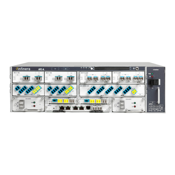
Page 34: Figure 2-1 Atc-A Front View
Figure 2-1 ATC-A Front View A front view of the ATC-P, with components and circuit packs, is shown in Figure 2-2 Figure 2-2 ATC -P Front View Infinera Corporation Infinera Corporation ATN Hardware Description Guide Release 1.0 Infinera Proprietary and Confidential... -
Page 35: Atc Thermal Loading
Natural Convection 0.110 Vertical empty space calculation based on Typical Aisle Widths for a Typical 20 x 20 feet Bay (GR-63- Frame Depth = 18 inches CORE, Figure 2-3) Infinera Corporation ATN Hardware Description Guide Release 1.0 Infinera Proprietary and Confidential... -
Page 36: Table 2-7 Atc Maximum Heat Release (19-Inch Frame)
119.6 112.1 105.5 99.7 94.4 89.7 85.4 81.5 119.6 112.1 105.5 99.7 94.4 89.7 85.4 81.5 78.0 112.1 105.5 99.7 94.4 89.7 85.4 81.5 78.0 74.7 Infinera Corporation Infinera Corporation ATN Hardware Description Guide Release 1.0 Infinera Proprietary and Confidential... -
Page 37: Table 2-8 Atc Typical Heat Release (23-Inch Frame)
Table 2-8 ATC Typical Heat Release (23-inch frame) ATC Typical Heat Release Calculation for 23-inch (600mm) Frame Power Consump- tion (Watts) Frame Depth (feet) Frame Width 2.167 (feet) Equipment 0.437 Height (feet) Infinera Corporation ATN Hardware Description Guide Release 1.0 Infinera Proprietary and Confidential... - Page 38 Vertical empty space calculation based on Typical Aisle Widths for a Typical 20 x 20 feet Bay (GR-63- Frame Depth = 24 inches CORE, Figure 2-6) Infinera Corporation Infinera Corporation ATN Hardware Description Guide Release 1.0 Infinera Proprietary and Confidential...
-
Page 39: Table 2-9 Atc Maximum Heat Release (23-Inch Frame)
Forced-air Fans 1.395 Vertical empty space calculation based on Typical Aisle Widths for a Typical 20 x 20 feet Bay (GR- Frame Depth = 12 inches 63-CORE, Figure 2-2) Infinera Corporation ATN Hardware Description Guide Release 1.0 Infinera Proprietary and Confidential... - Page 40 Vertical empty space calculation based on Typical Aisle Widths for a Typical 20 x 20 feet Bay (GR- Frame Depth = 24 inches 63-CORE, Figure 2-6) Infinera Corporation Infinera Corporation ATN Hardware Description Guide Release 1.0 Infinera Proprietary and Confidential...
-
Page 41: Atc Product Details
The ATC can be deployed as an Active Chassis (ATC-A) or a Passive Chassis (ATC-P) within an The ATC is used in ATN Terminal and ATN Add/Drop configurations The ATC can be installed in an 19-inch or 23-inch ANSI or ETSI rack ... -
Page 42: Mechanical Specifications
Depth 11.54 inches / 293.0mm (Overall Chassis depth) Weight - with backplane and 21lbs / 9.53kg alarm card Weight - fully loaded chassis 43.91lbs / 19.96kg Infinera Corporation Infinera Corporation ATN Hardware Description Guide Release 1.0 Infinera Proprietary and Confidential... -
Page 43: Figure 2-3 Atc-A Dimensions
Parameter Specification Mechanical specifications Height 3.5 inches Width 17.48 inches Depth 11.54 inches (Overall Chassis depth) Weight 14lbs / 6.35kg Weight - fully loaded chassis 34.23lbs / 15.56kg Infinera Corporation ATN Hardware Description Guide Release 1.0 Infinera Proprietary and Confidential... -
Page 44: Rack Mounting Ears
19-inch or 23-inch ANSI or ETSI rack. Power Conversion Module (PCM) Table 2-13 lists the name and a brief description of the supported PCM. Table 2-13 ATN Power Conversion Module Product Ordering Name (PON) Features PCM-48VDC Power Conversion Module- DC The front lower corners of the ATC accommodate up to two hot-pluggable -48V DC Power Conversion Modules (PCM-48VDC). -
Page 45: Dc Power Conversion Module (Pcm-48Vdc)
Page 17 DC Power Conversion Module (PCM-48VDC) The ATN includes two redundant DC power conversion modules in each ATC-A. The DC power conversion module, PCM-48VDC receives a -48V DC input feed, converts it to +12V DC and distributes the +12V DC to all slots. It also generates +3.3VDC that is provided to passive cards and the Alarm card for light loads. -
Page 46: Power Leds
-48V DC Power and the second to its Return. Power cables are connected to the PCM either by direct bare wire connection, or through the use of lugs. A plastic safety cover is provided to prevent inadvertent contact with the terminals once installed. Infinera Corporation Infinera Corporation ATN Hardware Description Guide Release 1.0 Infinera Proprietary and Confidential... -
Page 47: Technical Specifications
PCM A and PCM B distribute the power supply to the power connectors on top of the backplane. The backplane feeds the power supply from each PCM to the circuit packs as shown in Figure 2-6. Figure 2-6 ATC Power Distribution Diagram Infinera Corporation ATN Hardware Description Guide Release 1.0 Infinera Proprietary and Confidential... -
Page 48: Alarm Panel
Indicates the presence (lit) or absence (dimmed) of Minor alarms in the chassis Yellow Indicates the presence (lit) or absence (dimmed) of the Alarm Cutoff function Infinera Corporation Infinera Corporation ATN Hardware Description Guide Release 1.0 Infinera Proprietary and Confidential... -
Page 49: Alarm Cutoff (Aco) Indicators
The alarm pin positions are shown in Figure 2-8. Figure 2-8 ATC Alarm Input/Output Contacts The input and output connector details are provided in Table 2-18. Infinera Corporation ATN Hardware Description Guide Release 1.0 Infinera Proprietary and Confidential... -
Page 50: Technical Specifications
User defined Alarm Input Contact 3 User defined Alarm Input Contact 3 User defined Alarm Input Contact 4 User defined Alarm Input Contact 4 User defined Infinera Corporation Infinera Corporation ATN Hardware Description Guide Release 1.0 Infinera Proprietary and Confidential... -
Page 51: Alarm Output Contact Pin Assignments
Predefined Reserved for Alarm Cutoff (ACO) a. ACO can be enabled using the input contact pins in addition to the ACO push button and the ATN GNM user interface. Alarm Output Contact Pin Assignments Table 2-21 lists the assignment of alarm output contact pins for the ATC. Six alarm contacts are pre- defined in the system and the remaining four contacts can be customized by the users to monitor the environmental alarms. - Page 52 Predefined NORMALLY CLOSED Major Visual Alarm, Predefined NORMALLY OPEN Critical Audio Alarm, Predefined COMMON Critical Audio Alarm, Predefined NORMALLY CLOSED Critical Audio Alarm, Predefined NORMALLY OPEN Infinera Corporation Infinera Corporation ATN Hardware Description Guide Release 1.0 Infinera Proprietary and Confidential...
- Page 53 Table 2-21 ATC Alarm Output Contact Pin Assignments Description Function Column Critical Visual Alarm, Predefined COMMON Critical Visual Alarm, Predefined NORMALLY CLOSED Critical Visual Alarm, Predefined NORMALLY OPEN Infinera Corporation ATN Hardware Description Guide Release 1.0 Infinera Proprietary and Confidential...
-
Page 54: Fan Tray
Indicates the presence or absence of power supply to the fan tray FAULT Indicates the presence or absence of a fault condition with the fan tray Infinera Corporation Infinera Corporation ATN Hardware Description Guide Release 1.0 Infinera Proprietary and Confidential... -
Page 55: Technical Specifications
2-28). Air is filtered at 80% dust arrestance. To ensure adequate cooling of the ATC the air filter must be inspected at regular intervals and possibly replaced. Infinera recommends inspecting the air filter once every six months. Mechanical Specifications Table 2-24 provides the mechanical specifications for the ATC air filter. -
Page 56: Fiber Management Guide And Cable Guides
Figure 2-10 Fan Tray with Air Filter Fiber Management Guide and Cable Guides The Infinera ATN can be equipped with an optional Fiber management Guide and Cable Management Guides. For additional information refer to the following sections: “Fiber Management Guide” on page 2-29 ... -
Page 57: Fiber Management Guide
Page 29 Figure 2-11 ATN with Fiber and Cable Guides Fiber Management Guide An optional fiber management guide can be used in conjunction with the ATC. The Fiber management guide is one rack unit high (1.75”) and is designed to be mounted to the equipment rack on top of an ATC. -
Page 58: Cable Management Guides
Page 30 Figure 2-12 ATN Fiber Guide Assembly Cable Management Guides In addition to the fiber management guide, there are three cable management guides that can be mounted directly to the ATC, one each on the right and left sides of the chassis and one in the middle. Along with the fiber management guide, the cable guides maximize valuable rack space and help to eliminate the pinching of cables in addition to providing correct cable bend radius. -
Page 59: Card Cage
Page 31 Figure 2-13 ATN Cable Guide Assemblies Card Cage The ATC-A and the ATC-P contain a single card cage to house the various circuit packs. The card cage for the ATC-A and ATC-P are described in the following topics: “ATC-A Card Cage”... -
Page 60: Atc-P Card Cage
Slots 1 to 8 are flexible slots and house Service Interface Modules (SIMs) and/or Optical Filter Modules (OFMs). Slots 9 and 10 are reserved for the ATN Amplification Module (AAM) or Passive OSC Add/Drop module (OFM-1-OSC) and slot 11 is reserved for the ATN Management Module (AMM). -
Page 61: Figure 2-15 Atc-P Card Cage
Page 33 Figure 2-15 ATC-P Card Cage Table 2-27 ATC-P Chassis Slot Assignments ATC Chassis Slot Number Module Type Infinera Corporation ATN Hardware Description Guide Release 1.0 Infinera Proprietary and Confidential... -
Page 62: Atn Management Module (Amm)
The AMM-A module occupies slot 11 of the ATC and provides shelf controller functionality for all modules resident within the chassis. Each ATC-A must be equipped with an AMM-A. The AMM-A contains the system software and configuration database for the ATN and performs the following: Management gateway functions to the external Data Communications Network (DCN) ... -
Page 63: Block Diagram
Channels (OSC channels) labeled as OSC-W and OSC-E. The OSC connection has 100M Ethernet over a wavelength of 1451nm through the SFP ports. Block Diagram Figure 2-16 AMM-A Functional Block Diagram Infinera Corporation ATN Hardware Description Guide Release 1.0 Infinera Proprietary and Confidential... -
Page 64: External Indicators And Connectors
Indicates the presence (lit) or absence (off) of an alarm on the cir- cuit pack: Critical, Major, or Minor NC (Node Controller) Green Indicates the circuit pack function: Node Controller (Green) or Not a Node Controller (off) Infinera Corporation Infinera Corporation ATN Hardware Description Guide Release 1.0 Infinera Proprietary and Confidential... -
Page 65: Connectors
The port is not active LOS (Loss Of Signal) Loss of signal No loss of signal Technical Specifications Table 2-33 provides the mechanical and electrical specifications for the AMM-A. Infinera Corporation ATN Hardware Description Guide Release 1.0 Infinera Proprietary and Confidential... -
Page 66: Table 2-33 Amm-A Technical Specifications
0.87 inches / 22.10mm Width 7.44 inches / 188.94mm Depth 10.73 inches / 272.50mm Weight 1.1lbs / 0.5kgs Electrical specifications Power consumption Table 2-1 on page 2-2 Infinera Corporation Infinera Corporation ATN Hardware Description Guide Release 1.0 Infinera Proprietary and Confidential... -
Page 67: Atn Amplifier Module (Aam)
Page 39 ATN Amplifier Module (AAM) There are two types of ATN Amplifier Modules (AAMs) supported on the ATC. The AAMs are used to provide amplification in DWDM systems. The AAM occupies slot 9 and/or slot 10 of the ATC. -
Page 68: External Indicators And Connectors
Figure 2-19 AAM-P1 Functional Block Diagram External Indicators and Connectors The AAM provides circuit pack status LED indicators as follows: AAM-B1 as shown in Figure 2-20 on page 2-41 Infinera Corporation Infinera Corporation ATN Hardware Description Guide Release 1.0 Infinera Proprietary and Confidential... -
Page 69: Circuit Pack Level Leds
Table 2-36 AAM-B1 and AAM-P1 Connectors Connector Type Purpose Line IN LC, Front access Connects from the line side fibers Line OUT LC, Front access Connects to the line side fibers Infinera Corporation ATN Hardware Description Guide Release 1.0 Infinera Proprietary and Confidential... -
Page 70: Technical Specifications
Table 2-38 AAM-B1 and AAM-P1 Optical Specifications Type Parameter Specification Line side optics Wavelength spacing 100GHz Wavelength frequency range 1530.33-1563.05nm ITU Grid Wavelength 1451nm Format 100M Ethernet Infinera Corporation Infinera Corporation ATN Hardware Description Guide Release 1.0 Infinera Proprietary and Confidential... -
Page 71: Optical Filter Modules (Ofm)
For example, OFM-10-D-M-5059 indicates a 10 channel DWDM Multiplexer/Demultiplexer supporting signals within Channel 50 to Channel 59. For more information on the optical channel plan, refer to Infinera ATN System Description Guide. - Page 72 • 1551nm OFM-2-C-A-4957 2-Channel CWDM OADM Module with Express Port — Sub-Band 2 (consisting of channels with the following corresponding wave- lengths): • 1491nm • 1571nm Infinera Corporation Infinera Corporation ATN Hardware Description Guide Release 1.0 Infinera Proprietary and Confidential...
-
Page 73: 10-Channel Dwdm Ofms
Red/Blue (R/B) filter. The Band 3 filter can be connected to the OFM-10-D-M-1827 and the R/B port can be connected to the OFM-10-D-M-5059. Optical Filter Module OFM-10-D-M-1827 Infinera Corporation ATN Hardware Description Guide Release 1.0 Infinera Proprietary and Confidential... -
Page 74: Block Diagram
The functional block diagram of OFM-10-D-M-4049 is shown in Figure 2-23. Figure 2-23 OFM-10-D-M-4049 Functional Block Diagram The functional block diagram of OFM-10-D-M-2837 is shown in Figure 2-24. Infinera Corporation Infinera Corporation ATN Hardware Description Guide Release 1.0 Infinera Proprietary and Confidential... -
Page 75: Figure 2-24 Ofm-10-D-M-2837 Functional Block Diagram
Page 47 Figure 2-24 OFM-10-D-M-2837 Functional Block Diagram The functional block diagram of OFM-10-D-M-1827 is shown in Figure 2-25. Figure 2-25 OFM-10-D-M-1827 Functional Block Diagram Infinera Corporation ATN Hardware Description Guide Release 1.0 Infinera Proprietary and Confidential... -
Page 76: External Connectors
The OFM card does not have any visual indicators. The line/port connectors are as shown in Figure 2-26 Figure 2-29. Figure 2-26 OFM-10-D-M-5059 Faceplate Figure 2-27 OFM-10-D-M-4049 Faceplate Infinera Corporation Infinera Corporation ATN Hardware Description Guide Release 1.0 Infinera Proprietary and Confidential... -
Page 77: Connectors
Connects from SFP/XFP TOM of the corresponding wave- length on the SIM Channel 59 OUT LC/UPC Connects to the SFP/XFP TOM of the corresponding wave- length on the SIM Infinera Corporation ATN Hardware Description Guide Release 1.0 Infinera Proprietary and Confidential... - Page 78 Connects from SFP/XFP TOM of the corresponding wave- length on the SIM Channel 50 OUT LC/UPC Connects to the SFP/XFP TOM of the corresponding wave- length on the SIM Infinera Corporation Infinera Corporation ATN Hardware Description Guide Release 1.0 Infinera Proprietary and Confidential...
-
Page 79: Table 2-41 Ofm-10-D-M-4049 Connectors
Connects to the SFP/XFP TOM of the corresponding wave- length on the SIM Channel 42 IN LC/UPC Connects from SFP/XFP TOM of the corresponding wave- length on the SIM Infinera Corporation ATN Hardware Description Guide Release 1.0 Infinera Proprietary and Confidential... -
Page 80: Table 2-42 Ofm-10-D-M-2837 Connectors
Connects from SFP/XFP TOM of the corresponding wave- length on the SIM Channel 36 OUT LC/UPC Connects to the SFP/XFP TOM of the corresponding wave- length on the SIM Infinera Corporation Infinera Corporation ATN Hardware Description Guide Release 1.0 Infinera Proprietary and Confidential... - Page 81 Connects from SFP/XFP TOM of the corresponding wave- length on the SIM Channel 28 OUT LC/UPC Connects to the SFP/XFP TOM of the corresponding wave- length on the SIM Infinera Corporation ATN Hardware Description Guide Release 1.0 Infinera Proprietary and Confidential...
-
Page 82: Table 2-43 Ofm-10-D-M-1827 Connectors
Connects from SFP/XFP TOM of the corresponding wave- length on the SIM Channel 21 OUT LC/UPC Connects to the SFP/XFP TOM of the corresponding wave- length on the SIM Infinera Corporation Infinera Corporation ATN Hardware Description Guide Release 1.0 Infinera Proprietary and Confidential... -
Page 83: Technical Specifications
Table 2-44 10-channel DWDM OFM Technical Specifications Type Parameter Specification Mechanical specifications Height 1.3 inches / 33.02 mm Width 7.2 inches / 182.88mm Depth 11.1 inches / 281.94mm Weight 3.3lbs Infinera Corporation ATN Hardware Description Guide Release 1.0 Infinera Proprietary and Confidential... -
Page 84: Optical Specifications
• Channel 43 • 1542.94 • 194.3 • Channel 42 • 1543.73 • 194.2 • Channel 41 • 1544.53 • 194.1 • Channel 40 • 1545.32 • 194.0 Infinera Corporation Infinera Corporation ATN Hardware Description Guide Release 1.0 Infinera Proprietary and Confidential... -
Page 85: Cascaded 10-Channel Dwdm Optical Filter Modules
The third 10-channel DWDM OFM card, OFM-10-D-M-2837 has a second 10-skip 0 band filter built- in for expansion to the fourth card (OFM-10-D-M-1827). The fourth 10-channel DWDM OFM card, OFM-10-D-M-1827 is a pure Multiplexer/Demultiplexer card. For expansion, Infinera Corporation ATN Hardware Description Guide Release 1.0 Infinera Proprietary and Confidential... -
Page 86: Figure 2-30 Cascaded 10-Channel Dwdm Ofms
Band 3 port of the OFM-10-D-M-2837 connects to Band 4 port of the OFM-10-D-M-1827 The R/B port of OFM-10-D-M-5059 connects to R/B port of OFM-10-D-M-2837 Figure 2-30 Cascaded 10-Channel DWDM OFMs Infinera Corporation Infinera Corporation ATN Hardware Description Guide Release 1.0 Infinera Proprietary and Confidential... -
Page 87: 4-Channel Dwdm Ofms
OFM-4-D-A-4043 OFM-4-D-A-3437 OFM-4-D-A-3033 OFM-4-D-A-2629 OFM-4-D-A-2225 OFM-4-D-A-1821 Block Diagram The functional block diagram of a 4-channel DWDM OFM is shown in Figure 2-31. Infinera Corporation ATN Hardware Description Guide Release 1.0 Infinera Proprietary and Confidential... -
Page 88: Figure 2-31 4-Channel Dwdm Ofm Functional Block Diagram
Page 60 Figure 2-31 4-channel DWDM OFM Functional Block Diagram Infinera Corporation Infinera Corporation ATN Hardware Description Guide Release 1.0 Infinera Proprietary and Confidential... -
Page 89: External Connectors
Connects from SFP/XFP TOM of the corresponding wave- length on the SIM Channel 58 OUT LC/UPC Connects to the SFP/XFP TOM of the corresponding wave- length on the SIM Infinera Corporation ATN Hardware Description Guide Release 1.0 Infinera Proprietary and Confidential... - Page 90 Connects from SFP/XFP TOM of the corresponding wave- length on the SIM Channel 49 OUT LC/UPC Connects to the SFP/XFP TOM of the corresponding wave- length on the SIM Infinera Corporation Infinera Corporation ATN Hardware Description Guide Release 1.0 Infinera Proprietary and Confidential...
- Page 91 Connects from SFP/XFP TOM of the corresponding wave- length on the SIM Channel 40 OUT LC/UPC Connects to the SFP/XFP TOM of the corresponding wave- length on the SIM Infinera Corporation ATN Hardware Description Guide Release 1.0 Infinera Proprietary and Confidential...
- Page 92 Connects to the SFP/XFP TOM of the corresponding wave- length on the SIM OFM-4-D-A-2629 Connectors Channel 29 IN LC/UPC Connects from SFP/XFP TOM of the corresponding wave- length on the SIM Infinera Corporation Infinera Corporation ATN Hardware Description Guide Release 1.0 Infinera Proprietary and Confidential...
- Page 93 Connects to the SFP/XFP TOM of the corresponding wave- length on the SIM Channel 20 IN LC/UPC Connects from SFP/XFP TOM of the corresponding wave- length on the SIM Infinera Corporation ATN Hardware Description Guide Release 1.0 Infinera Proprietary and Confidential...
-
Page 94: Technical Specifications
Type Parameter Specification Mechanical specifications Height 1.3 inches / 33.02 mm Width 3.6 inches / 91.44 mm Depth 11.1 inches / 281.94 mm Weight 1.9 lbs Infinera Corporation Infinera Corporation ATN Hardware Description Guide Release 1.0 Infinera Proprietary and Confidential... -
Page 95: Optical Specifications
• 1550.92 • 193.3 30-33) wavelength • Channel 32 • 1551.72 • 193.2 range • Channel 31 • 1552.52 • 193.1 • Channel 30 • 1553.33 • 193.0 Infinera Corporation ATN Hardware Description Guide Release 1.0 Infinera Proprietary and Confidential... -
Page 96: 8-Channel Cwdm Ofm
It is a Multiplexer/Demultiplexer module that includes OSC add/drop ability. It supports eight CWDM channels at 20nm channel spacing. It supports the entire CWDM channel range for the ATN and has eight add/drop ports corresponding to the channels Block Diagram... -
Page 97: External Connectors
Connects to the line fiber OSC IN LC/UPC OSC port connects from the AMM OSC TOM OUT port OSC OUT LC/UPC OSC port connects to the AMM OSC TOM IN port Infinera Corporation ATN Hardware Description Guide Release 1.0 Infinera Proprietary and Confidential... - Page 98 Connects from SFP/XFP TOM of the corresponding wave- length on the SIM 1611nm OUT LC/UPC Connects to the SFP/XFP TOM of the corresponding wave- length on the SIM Infinera Corporation Infinera Corporation ATN Hardware Description Guide Release 1.0 Infinera Proprietary and Confidential...
-
Page 99: Technical Specifications
Channel 7 1591 nm Channel 8 1611 nm Note: Only Channel 3, 4, 5 and 6 are available for 10GbE, OC-192 and STM-64 signal support in future releases. Infinera Corporation ATN Hardware Description Guide Release 1.0 Infinera Proprietary and Confidential... -
Page 100: 2-Channel Cwdm Ofms
Block Diagram The functional block diagram of the two channel CWDM OFM is shown in Figure 2-35. Figure 2-35 2-Channel CWDM OFM Functional Block Diagram Infinera Corporation Infinera Corporation ATN Hardware Description Guide Release 1.0 Infinera Proprietary and Confidential... -
Page 101: External Connectors
Connects from a 1491 nm SFP/XFP TOM on the SIM 1491 OUT LC/UPC Connects to a 1491 nm SFP/XFP TOM on the SIM 1571 IN LC/UPC Connects from a 1571 nm SFP/XFP TOM on the SIM Infinera Corporation ATN Hardware Description Guide Release 1.0 Infinera Proprietary and Confidential... -
Page 102: Technical Specifications
Type Parameter Specification Mechanical specifications Height 1.3 inches / 33.02 mm Width 3.6 inches / 91.44 mm Depth 11.1 inches / 281.94 mm Weight 1.9 lbs Infinera Corporation Infinera Corporation ATN Hardware Description Guide Release 1.0 Infinera Proprietary and Confidential... -
Page 103: Optical Specifications
Channel 7 1591 nm Channel 8 1611 nm Note: Only Channel 3, 4, 5 and 6 are available for 10GbE, OC-192 and STM-64 signal support in future releases. Infinera Corporation ATN Hardware Description Guide Release 1.0 Infinera Proprietary and Confidential... -
Page 104: Passive Osc Add/Drop Module
Page 76 Passive OSC Add/Drop Module The OSC is an optical supervisory channel used for out-of-band communications between ATN network elements. The passive OSC module (OFM-1-OSC) provides add/drop capabilities for the Infinera ATNs at 1451nm OSC. For optical spans that do not require optical amplification, the passive OSC module (OFM-1- OSC) will be used in place of an AAM for line side connectivity. -
Page 105: Connectors
Table 2-56 OFM-1-OSC Technical Specifications Type Parameter Specification Mechanical specifications Height 0.7 inches / 17.78 mm Width 3.6 inches / 91.44 mm Depth 11.1 inches / 281.94 mm Weight 0.6lbs Infinera Corporation ATN Hardware Description Guide Release 1.0 Infinera Proprietary and Confidential... -
Page 106: Optical Specifications
Table 2-57 OFM-1-OSC Optical Specifications Type Parameter Specification Line side optics Wavelength spacing 100 GHz Wavelength frequency range 1530.33-1563.05 nm ITU Grid Wavelength 1451 nm Format 100M Ethernet Infinera Corporation Infinera Corporation ATN Hardware Description Guide Release 1.0 Infinera Proprietary and Confidential... -
Page 107: Service Interface Module (Sim)
The SIM-T-1-10G provides performance monitoring for both the line and client interfaces for 10GbE and OC-192/STM-64 applications. The user can configure the EFEC mode for extra gain. Infinera Corporation ATN Hardware Description Guide Release 1.0 Infinera Proprietary and Confidential... -
Page 108: Block Diagram
Page 80 Block Diagram Figure 2-39 SIM-T-1-10G Functional Block Diagram Infinera Corporation Infinera Corporation ATN Hardware Description Guide Release 1.0 Infinera Proprietary and Confidential... -
Page 109: External Indicators And Connectors
Indicates active/inactive status of the port. Solid Green indicates Active), solid Yellow (Standby), flashing Yellow (In maintenance) Indicates the status of the XFP signal. During a Loss of Signal (LOS) condition, this indicator will be lit Infinera Corporation ATN Hardware Description Guide Release 1.0 Infinera Proprietary and Confidential... -
Page 110: Interface Specifications
Table 2-62 SIM-T-1-10G Interface Specifications Type Parameter Specification Client protocols • OC192 OTU2 and OTU2e • STM-16 • 10GbE LAN • 10GbE WAN Capacity Maximum capacity 11.1Gbps Infinera Corporation Infinera Corporation ATN Hardware Description Guide Release 1.0 Infinera Proprietary and Confidential... -
Page 111: Sim Module 2.5G (Sim-T-2-2.5Gm)
Supports clock and data recovery (CDR) only and does not map the client signal into any other for- Block Diagram Figure 2-41 SIM-T-2-2.5GM Functional Block Diagram Infinera Corporation ATN Hardware Description Guide Release 1.0 Infinera Proprietary and Confidential... -
Page 112: External Indicators And Connectors
Active), solid Yellow (Standby), flashing Yellow (In maintenance) Indicates the status of the SFP signal. During a Loss of Signal (LOS) condition, this indicator will be lit Infinera Corporation Infinera Corporation ATN Hardware Description Guide Release 1.0 Infinera Proprietary and Confidential... -
Page 113: Technical Specifications
Tributary protocols • OC-3 OTU1 • OC-12 • OC-48 • STM-1 • STM-4 • STM-16 • Fibre Channel 1G • Fibre Channel 2G • ESCON • OTU1 Capacity 2.7G Infinera Corporation ATN Hardware Description Guide Release 1.0 Infinera Proprietary and Confidential... -
Page 114: Tributary Optical Module (Tom)
The TOM is hot-pluggable into any of the corresponding SIMs, and is powered through the pluggable interface. Table 2-67 lists the name and a brief description of each of the supported TOMs Infinera Corporation Infinera Corporation ATN Hardware Description Guide Release 1.0 Infinera Proprietary and Confidential... -
Page 115: Table 2-67 Tom Product Details
Value (n=18 to 37 and 40 to 59) corresponds to specific operating frequencies b. Value (n=18 to 37 and 40 to 59) corresponds to specific operating frequencies c. Value (n=47,49,51,53,55,57,59 and 61) corresponds to specific wavelengths Infinera Corporation ATN Hardware Description Guide Release 1.0 Infinera Proprietary and Confidential... -
Page 116: Tributary Optical Module 10G-Dn-Lr2 (Tom-10G-Dn-Lr2)
Product Features TOM-10G-Dn-LR2 Parameter Description Product Ordering Name 10G Tributary Optical Module, TOM-10G-Dn-LR2 (n=18-37 and 40-59) Reach • GR-253 CORE OC-192 LR-2 • ITU-T G.959.1 P1L1-2D2 Infinera Corporation Infinera Corporation ATN Hardware Description Guide Release 1.0 Infinera Proprietary and Confidential... - Page 117 • TOM-10G-D40-LR2: 194.0THz, 1545.32nm • TOM-10G-D41-LR2: 194.1THz, 1544.53nm • TOM-10G-D42-LR2: 194.2THz, 1543.73nm • TOM-10G-D43-LR2: 194.3THz, 1542.94nm • TOM-10G-D44-LR2: 194.4THz, 1542.14nm • TOM-10G-D45-LR2: 194.5THz, 1541.35nm • TOM-10G-D46-LR2: 194.6THz, 1540.56nm (continued...) Infinera Corporation ATN Hardware Description Guide Release 1.0 Infinera Proprietary and Confidential...
-
Page 118: Functional Description
OTU2 (OC-192/SDH-64 + FEC) OTU2e (10GbE + FEC) TOM-10GDn-LR2 port status LEDs are located on the SIM-T-1-10G as shown in Figure 2-40 on page 2- Infinera Corporation Infinera Corporation ATN Hardware Description Guide Release 1.0 Infinera Proprietary and Confidential... -
Page 119: Connectors
Width 0.34 inches / 8.64mm Depth 3.10 inches / 78.74mm Weight 0.1lbs (approximately) Electrical specifications Power consumption Included as part of the SIM; Table 2-1 on page 2-2 Infinera Corporation ATN Hardware Description Guide Release 1.0 Infinera Proprietary and Confidential... -
Page 120: Optical Specifications
Complies with: • GR-253 CORE OC-192 LR-25 • ITU-T G.959.1 P1L1-2D2 Transmitter output power -1dBm to +3dBm Transmitter wavelength 1530nm to 1565nm Data rate 9.95Gbps to 11.3Gbps Infinera Corporation Infinera Corporation ATN Hardware Description Guide Release 1.0 Infinera Proprietary and Confidential... -
Page 121: Interface Specifications
2-73. Table 2-73 TOM-10G-Dn-LR2 Facilities Type Parameter Specification Tributary protocols 10GbE LAN PHY Fully transparent 10GbE WAN PHY Fully transparent SONET OC-192 Fully transparent SDH STM-64 Fully transparent Infinera Corporation ATN Hardware Description Guide Release 1.0 Infinera Proprietary and Confidential... -
Page 122: Tributary Optical Module Mr-Dn-Lr2 (Tom-Mr-Dn-Lr2)
Product Ordering Name 2.5G Tributary Optical Module, TOM-MR-Dn-LR2 (n=18 to 37 and 40 to 59) Reach • GR 253 CORE OC48 LR-2 • ITU-T G.957 L-16.2 Infinera Corporation Infinera Corporation ATN Hardware Description Guide Release 1.0 Infinera Proprietary and Confidential... - Page 123 • TOM-MR-D40-LR2: 194.0THz, 1545.32nm • TOM-MR-D41-LR2: 194.1THz, 1544.53nm • TOM-MR-D42-LR2: 194.2THz, 1543.73nm • TOM-MR-D43-LR2: 194.3THz, 1542.94nm • TOM-MR-D44-LR2: 194.4THz, 1542.14nm • TOM-MR-D45-LR2: 194.5THz, 1541.35nm • TOM-MR-D46-LR2: 194.6THz, 1540.56nm (continued...) Infinera Corporation ATN Hardware Description Guide Release 1.0 Infinera Proprietary and Confidential...
-
Page 124: Functional Description
ESCON FICON OTU-1 with digital wrapper TOM-MR-Dn-LR2 port status LEDs are located on the SIM-T-2-2.5GM as shown in Figure 2-42 on page 2- Infinera Corporation Infinera Corporation ATN Hardware Description Guide Release 1.0 Infinera Proprietary and Confidential... -
Page 125: Connectors
Width 0.34 inches / 8.64mm Depth 3.10 inches / 78.74mm Weight 0.1lbs (approximately) Electrical specifications Power consumption Included as part of the SIM; Table 2-1 on page 2-2 Infinera Corporation ATN Hardware Description Guide Release 1.0 Infinera Proprietary and Confidential... -
Page 126: Optical Specifications
Complies with: • GR-253 CORE OC-48 LR-2 • ITU-T G.957 L-16.2 Transmitter output power 0dBm to +3.5dBm Transmitter wavelength 1500nm to 1580nm Data rate 0.155Gbps to 2.7Gbps Infinera Corporation Infinera Corporation ATN Hardware Description Guide Release 1.0 Infinera Proprietary and Confidential... -
Page 127: Interface Specifications
SDH STM-4 Fully transparent SDH STM-16 Fully transparent 1 GbE Fully transparent 1G Fibre Channel Fully transparent 2G Fibre Channel Fully transparent ESCON Fully transparent FICON Fully transparent Infinera Corporation ATN Hardware Description Guide Release 1.0 Infinera Proprietary and Confidential... -
Page 128: Tributary Optical Module Mr-Cn-Lr2 (Tom-Mr-Cn-Lr2)
ESCON FICON OTU-1 with digital wrapper TOM-MR-Cn-LR2 port status LEDs are located on the SIM-T-2-2.5GM as shown in Figure 2-42 on page 2- Infinera Corporation Infinera Corporation ATN Hardware Description Guide Release 1.0 Infinera Proprietary and Confidential... -
Page 129: Connectors
Width 0.34 inches / 8.64mm Depth 3.10 inches / 78.74mm Weight 0.1lbs (approximately) Electrical specifications Power consumption Included as part of the SIM; Table 2-1 on page 2-2 Infinera Corporation ATN Hardware Description Guide Release 1.0 Infinera Proprietary and Confidential... -
Page 130: Optical Specifications
• CWDM 2.5Gbps SONET/SDH • CWDM 120km 2.5G Ethernet Transmitter output power >1dBm Transmitter wavelength 1471nm, 1491nm, 1511nm, 1531nm, 1551nm, 1571nm, 1591nm, 1611nm CWDM Data rate 0.155Gbps to 2.7Gbps Infinera Corporation Infinera Corporation ATN Hardware Description Guide Release 1.0 Infinera Proprietary and Confidential... -
Page 131: Interface Specifications
ITU short reach specification 10GBase-SR for the 10GbE LAN client signal and 10GBase-SW for the 10GbE WAN client signal. TOM-10G-SR0 port status LEDs are located on the SIM-T-1-10G as shown in Figure 2-40 on page 2-81. Infinera Corporation ATN Hardware Description Guide Release 1.0 Infinera Proprietary and Confidential... -
Page 132: Connectors
Table 2-89 TOM-10G-SR0 Tributary Port IN Optical Specifications Type Specification Incoming fiber type Multi-mode Receiver sensitivity -9.9dBm Receiver overload -1.0dBm Receiver wavelength 840nm to 860nm Data rate 9.95328Gbps to 10.3125Gbps Infinera Corporation Infinera Corporation ATN Hardware Description Guide Release 1.0 Infinera Proprietary and Confidential... -
Page 133: Interface Specifications
The tributary interface details are listed in Table 2-91. Table 2-91 TOM-10G-SR0 Tributary Facilities Type Parameter Specification Tributary protocols 10GbE LAN PHY Fully transparent 10GbE WAN PHY Fully transparent Infinera Corporation ATN Hardware Description Guide Release 1.0 Infinera Proprietary and Confidential... -
Page 134: Tributary Optical Module 10G-Sr1 (Tom-10G-Sr1)
Tributary port IN Connects to the transmit or output port of the client equipment Tributary port OUT Connects to receive or input port of the client equipment Infinera Corporation Infinera Corporation ATN Hardware Description Guide Release 1.0 Infinera Proprietary and Confidential... -
Page 135: Technical Specifications
• 10GbE WAN: IEEE 802.3ae 10GBase-LW • GR-253-CORE SR-1 • ITU-T G.693 VSR2000-2R1 Transmitter output power -6dBm to -1dBm Transmitter wavelength 1290nm to 1330nm Data rate 9.95Gbps to 10.3Gbps Infinera Corporation ATN Hardware Description Guide Release 1.0 Infinera Proprietary and Confidential... -
Page 136: Interface Specifications
Table 2-97 TOM-10G-SR1 Tributary Facilities Type Parameter Specification Tributary protocols 10GbE LAN PHY Fully transparent 10GbE WAN PHY Fully transparent SONET OC-192 Fully transparent SDH STM-64 Fully transparent Infinera Corporation Infinera Corporation ATN Hardware Description Guide Release 1.0 Infinera Proprietary and Confidential... -
Page 137: Tributary Optical Module 2.5G-Sr1 (Tom-2.5G-Sr1)
Purpose Tributary port IN Connects to the transmit or output port of the client equipment Tributary port OUT Connects to receive or input port of the client equipment Infinera Corporation ATN Hardware Description Guide Release 1.0 Infinera Proprietary and Confidential... -
Page 138: Technical Specifications
Single mode Link distance • GR-253-CORE OC-48 SR-1 • ITU-T G.957 I-16 Transmitter output power -10dBm to -3dBm Transmitter wavelength 1266nm to 1360nm Data rate 2.488Gbps Infinera Corporation Infinera Corporation ATN Hardware Description Guide Release 1.0 Infinera Proprietary and Confidential... -
Page 139: Interface Specifications
CORE IR2 specification for the OC-48 client signal and ITU G.957 S-16.2 for SDH STM-16 client signal. TOM-2.5G-IR2 port status LEDs are located on the SIM-T-2-2.5GM as shown in Figure 2-42 on page 2-84. Infinera Corporation ATN Hardware Description Guide Release 1.0 Infinera Proprietary and Confidential... -
Page 140: Connectors
Table 2-107 TOM-2.5G-IR2 Tributary port IN Optical Specifications Type Specification Incoming fiber type Single mode Receiver sensitivity -18.0dBm Receiver overload 0.0dBm Receiver wavelength 1260nm to 1580nm Data rate 2.5Gbps Infinera Corporation Infinera Corporation ATN Hardware Description Guide Release 1.0 Infinera Proprietary and Confidential... -
Page 141: Interface Specifications
Interface Specifications The tributary interface details are listed in Table 2-109. Table 2-109 TOM-2.5G-IR2 Tributary Facilities Type Parameter Specification Tributary protocols SONET OC-48 Fully transparent SDH STM-16 Fully transparent Infinera Corporation ATN Hardware Description Guide Release 1.0 Infinera Proprietary and Confidential... -
Page 142: Tributary Optical Module 2.5Gmr-Sr1 (Tom-2.5Gmr-Sr1)
STM-16, even when set to the lower OC-3/OC-12 or STM-1/STM-4 rates. Span engineer- ing should take this into consideration and optical attenuators should be applied, if appro- priate. Infinera Corporation Infinera Corporation ATN Hardware Description Guide Release 1.0 Infinera Proprietary and Confidential... -
Page 143: Connectors
Specification Incoming fiber type Single mode Receiver sensitivity • 2.5G: -18.0dBm • 1G: -20.0dBm • 155M: -23.0dBm Receiver overload • 2.5G: -3.0dBm • 1G: -3.0dBm • 155M: -8.0dBm Infinera Corporation ATN Hardware Description Guide Release 1.0 Infinera Proprietary and Confidential... -
Page 144: Table 2-114 Tom-2.5Gmr-Sr1 Tributary Port Out Optical Specifications
ITU-T G.957 S-16.1 ANSI T1.105/GR 253 CORE Transmitter output power -9.5dBm to -3dBm Transmitter wavelength 1270nm to 1360nm Data rate 2.5Gbps, 1Gbps, 622Mbps, 155Mbps user provisionable Infinera Corporation Infinera Corporation ATN Hardware Description Guide Release 1.0 Infinera Proprietary and Confidential... -
Page 145: Tributary Optical Module 2.5Gmr-Ir1 (Tom-2.5Gmr-Ir1)
STM-16, even when set to the lower OC-3/OC-12 or STM-1/STM-4 rates. Span engineer- ing should take this into consideration and optical attenuators should be applied, if appro- priate. Infinera Corporation ATN Hardware Description Guide Release 1.0 Infinera Proprietary and Confidential... -
Page 146: Connectors
Incoming fiber type Single mode Receiver sensitivity • 2.5G: -18.0dBm • 622M: -23.0dBm • 155M: -23.0dBm Receiver overload • 2.5G: 0.0dBm • 622M: -8.0dBm • 155M: -8.0dBm Infinera Corporation Infinera Corporation ATN Hardware Description Guide Release 1.0 Infinera Proprietary and Confidential... -
Page 147: Interface Specifications
Parameter Specification Tributary protocols SONET OC-48 Fully transparent SONET OC-12 Fully transparent SONET OC-3 Fully transparent SDH STM-16 Fully transparent SDH STM-4 Fully transparent SDH STM-1 Fully transparent Infinera Corporation ATN Hardware Description Guide Release 1.0 Infinera Proprietary and Confidential... -
Page 148: Tributary Optical Module 1G-Sx (Tom-1G-Sx)
Tributary port IN Connects to the transmit or output port of the client equipment Tributary port OUT Connects to receive or input port of the client equipment Infinera Corporation Infinera Corporation ATN Hardware Description Guide Release 1.0 Infinera Proprietary and Confidential... -
Page 149: Technical Specifications
Table 2-125 TOM-1G-SX Tributary Port OUT Optical Specifications Type Specification Outgoing fiber type Multi-mode Link distance IEEE 802.3z 1000Base-SX Transmitter output power -9.5dBm to -3dBm Transmitter wavelength 830nm to 860nm Data rate 1Gbps, 2.125Gbps Infinera Corporation ATN Hardware Description Guide Release 1.0 Infinera Proprietary and Confidential... -
Page 150: Interface Specifications
Table 2-126 TOM-1G-SX Tributary Facilities Type Parameter Specification Tributary protocols 1GbE Fully transparent FICON Fully transparent 1G Fibre Channel Fully transparent 2G Fibre Channel Fully transparent Infinera Corporation Infinera Corporation ATN Hardware Description Guide Release 1.0 Infinera Proprietary and Confidential... -
Page 151: Tributary Optical Module 1G-Lx (Tom-1G-Lx)
Purpose Tributary port IN Connects to the transmit or output port of the client equipment Tributary port OUT Connects to receive or input port of the client equipment Infinera Corporation ATN Hardware Description Guide Release 1.0 Infinera Proprietary and Confidential... -
Page 152: Technical Specifications
Specification Outgoing fiber type Single mode Link distance IEEE 802.3z 1000Base-LX Transmitter output power -9.5dBm to -3dBm Transmitter wavelength 1270nm to 1355nm Data rate 1Gbps, 2.125Gbps Infinera Corporation Infinera Corporation ATN Hardware Description Guide Release 1.0 Infinera Proprietary and Confidential... -
Page 153: Interface Specifications
TOM-100M-C45-L2s are hot-pluggable into the AMM-A and are powered through the pluggable interface. TOM-100M-C45-L2 supports 1451nm OSC wavelength, 100Mbps Ethernet signals and allows for OSC termination on the AMM-A. Infinera Corporation ATN Hardware Description Guide Release 1.0 Infinera Proprietary and Confidential... -
Page 154: Connectors
0.33 inches / 8.38mm Depth 2.23 inches / 56.64mm Weight 0.1lbs (approximately) Electrical specifications Power consumption Included as part of the SIM; Table 2-1 on page 2-2 Infinera Corporation Infinera Corporation ATN Hardware Description Guide Release 1.0 Infinera Proprietary and Confidential... -
Page 155: Optical Specifications
Data rate 100Mbps Interface Specifications The tributary interface details are listed in Table 2-138. Table 2-138 TOM-100M-C45-L2 Tributary Facilities Type Parameter Specification Tributary protocols Fast Ethernet Fully transparent Infinera Corporation ATN Hardware Description Guide Release 1.0 Infinera Proprietary and Confidential... - Page 156 Page 128 Infinera Corporation Infinera Corporation ATN Hardware Description Guide Release 1.0 Infinera Proprietary and Confidential...
- Page 157 Infinera Dispersion Management Chassis The Infinera Dispersion Management Chassis, referred to as the DMC, is a rack mountable passive chassis. The DMC does not require power or management. DMCs are used to house Dispersion Compensation Modules (DCMs). Depending on the span characteristics, the DMC is optionally included in ATN network elements to provide dispersion compensation.
-
Page 158: Dmc Overview
Figure 3-1 on page 3-2 Figure 3-2 on page 3-3. See “Dispersion Compensation Module (DCM)” on page 3-6 for more information. Figure 3-1 DMC-B with Half-width DCMs infn_029 Infinera Corporation Infinera Corporation ATN Hardware Description Guide Release 1.0 Infinera Proprietary and Confidential... -
Page 159: Figure 3-2 Dmc-B With A Full-Width Dcm
Page 3 Figure 3-2 DMC-B with a Full-width DCM infn_028 Infinera Corporation ATN Hardware Description Guide Release 1.0 Infinera Proprietary and Confidential... -
Page 160: Dmc Product Details
2 each 590-0156-001 (DMC1-B) in an ETSI (600mm) or 23-inch rack 120-0096-001 Mounting option for a DCM shelf 2 each 590-0215-001 (DMC1-B) in a 19-inch rack Infinera Corporation Infinera Corporation ATN Hardware Description Guide Release 1.0 Infinera Proprietary and Confidential... -
Page 161: Mechanical Specifications
DMC. Table 3-4 DMC Mechanical Specifications Type Parameter Specification Mechanical specifications Height 1.75 inches / 44.45mm Width 17.40 inches / 441.96mm Depth 11.00 inches / 279.4mm Weight 5.5lbs Infinera Corporation ATN Hardware Description Guide Release 1.0 Infinera Proprietary and Confidential... -
Page 162: Dispersion Compensation Module (Dcm)
Full-width, -1700ps/nm, Negative Dispersion DCM1F-1900N-LL Full-width, -1900ps/nm, Negative Dispersion DCM1H-100P-A Half-width, +100ps/nm, Positive Dispersion DCM1F-200P-A Full-width, +200ps/nm, Positive Dispersion DCM1F-300P-A Full-width, +300ps/nm, Positive Dispersion DCM1F-400L-A Full-width, -400ps/nm, Negative Dispersion Infinera Corporation Infinera Corporation ATN Hardware Description Guide Release 1.0 Infinera Proprietary and Confidential... -
Page 163: Functional Description
The half-width DCM type is shown in Figure 3-3 and the full-width DCM type is shown in Figure 3-4 on page 3-7. Figure 3-3 Half-width DCM infn_030 Figure 3-4 Full-width DCM infn_031 Infinera Corporation ATN Hardware Description Guide Release 1.0 Infinera Proprietary and Confidential... -
Page 164: Table 3-6 Dcm Mechanical Specifications
Table 3-7. Table 3-7 DCM Connectors Connector Type Purpose Optical interface connects to the Line-side fiber Optical interface connects to the Line-In port of an AAM Infinera Corporation Infinera Corporation ATN Hardware Description Guide Release 1.0 Infinera Proprietary and Confidential... - Page 165 Automatic Laser Shutdown ATN Management Module amplifier ANSI American National Standards Institute avalanche photo diode application programming interface automatic protection switching Alarm Reporting Control address resolution protocol Infinera Corporation ATN Hardware Description Guide Release 1.0 Infinera Proprietary and Confidential...
- Page 166 (now known as the ITU-T) CCLI commissioning command line interface chromatic dispersion equalizer clock and data recovery CDRH Center for Devices and Radiological Health code for federal regulations CH/Ch/ch channel Infinera Corporation ATN Hardware Description Guide Release 1.0 Infinera Proprietary and Confidential...
- Page 167 Dispersion Compensation Module data communication network DEMUX de-multiplexing distributed feedback decision feedback equalizer dynamic gain equalization Infinera Corporation ATN Hardware Description Guide Release 1.0 Infinera Proprietary and Confidential...
- Page 168 Federal Communications Commission (USA) Food and Drug Administration forward defect indication flight data recorder forward error correction FICON Fibre Connectivity Infinera Corporation ATN Hardware Description Guide Release 1.0 Infinera Proprietary and Confidential...
- Page 169 International Electrical Commission Infinera Management Suite input/output Internet protocol IQA NOS ATN Infinera IQA Network Operating System ATN intermediate reach in-service ITU-T International Telecommunications Union - Telecommunications Infinera Corporation ATN Hardware Description Guide Release 1.0...
- Page 170 MSOH multiplex section overhead MTBF mean time between failure maximum transmission unit Infinera Corporation ATN Hardware Description Guide Release 1.0 Infinera Proprietary and Confidential...
- Page 171 OC-192 optical carrier signal at 9.95328Gbps OC-3 optical carrier signal at 155.52Mbps OC-48 optical carrier signal at 2.48832Gbps optical channel open connection indication optical channel data unit optical-electrical-optical Infinera Corporation ATN Hardware Description Guide Release 1.0 Infinera Proprietary and Confidential...
- Page 172 Power Conversion Module physical coding sublayer protocol data unit; power distribution unit protection group physical protocol identifier positive-intrinsic negative positive justification opportunity programmable logic device phase locked loop Infinera Corporation ATN Hardware Description Guide Release 1.0 Infinera Proprietary and Confidential...
- Page 173 Reed-Solomon RSOH regenerator section overhead RSTP rapid spanning tree protocol real time clock return lead ready to send rack unit receiver; receive Rx Q receiver quality Infinera Corporation ATN Hardware Description Guide Release 1.0 Infinera Proprietary and Confidential...
- Page 174 SSHv2 Secure Shell version 2 secure sockets layer section terminating equipment synchronous transfer mode STM-1 SDH signal at 155.52Mbps STM-16 SDH signal at 2.48832Gbps Infinera Corporation ATN Hardware Description Guide Release 1.0 Infinera Proprietary and Confidential...
- Page 175 UART universal asynchronous receiver transmitter unavailable seconds UAS-L unavailable seconds, near-end line UAS-P unavailable seconds, near-end STS path user datagram protocol user-network interface UPSR unidirectional path switched ring Infinera Corporation ATN Hardware Description Guide Release 1.0 Infinera Proprietary and Confidential...
- Page 176 10Gbps small form factor pluggable extensible markup language MISC re-amplification re-amplification, re-shape re-amplification, re-shape, re-time re-amplification, re-shape, re-time, re-code Infinera Corporation ATN Hardware Description Guide Release 1.0 Infinera Proprietary and Confidential...
Need help?
Do you have a question about the ATN and is the answer not in the manual?
Questions and answers