Sign In
Upload
Manuals
Brands
Infineon Manuals
Controller
XDP XDPP1100A
Infineon XDP XDPP1100A Manuals
Manuals and User Guides for Infineon XDP XDPP1100A. We have
1
Infineon XDP XDPP1100A manual available for free PDF download: Reference Manual
Infineon XDP XDPP1100A Reference Manual (565 pages)
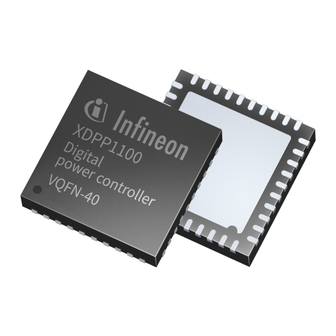
Digital power controller
Brand:
Infineon
| Category:
Controller
| Size: 4 MB
Table of Contents
About this Document
1
Table of Contents
2
Introduction
8
Applications
8
Control Registers and Pmbus Commands
8
Naming Conventions
9
Loops and Phases
9
Symbols and Abbreviations
9
Binary Number Format Convention
12
Structure of this Document
13
Voltage Sense
14
VS Module Configuration
15
Voltage Sense Analog-To-Digital Converter
18
Analog Front End and Front-End Compensation
19
Tracking ADC
19
Voltage Sense Processor
21
Output Voltage Processing
21
Rectification Voltage Processing
22
VRECT Timing for Single PWM Signal
23
RECT Watchdog Timer
23
Deglitcher
24
VRECT Timing for Two PWM Signals
25
Vin
25
VRECT Start-Up Programming
26
Same Cycle Response
27
VRECT Delay Counters
28
VS Registers
29
VIN Processing
29
Current Sense (IS)
38
Current Sense Module Configuration
39
Current Sense Analog to Digital Converter
41
Current Sense Analog Front End
42
Current Estimator
43
PWM State
44
Slope Estimator
49
Error Tracking
52
Trace Inductance of the PCB Current Sensing
53
Current Sense Processor
53
ADC Codes to Amps
54
Peak Current Limiting
55
Negative Current Limiting
55
Short-Circuit Protection
55
Error Tracking Fault Detection
56
Current Sense Registers
57
Current Sense Pmbus Commands
65
Telemetry Sense
67
Telemetry Sense ADC
67
TS Input Mux and Sequencing
67
Telemetry Sense Current DAC
70
Telemetry Sense Processor
70
Sequencer
71
Gain and Offset Correction
71
Internal Temperature (ITSEN) Computation
72
VIN Computation
72
X-Valent Measurement
73
Telemetry Sense Registers
74
Voltage Control
81
Pmbus Commands to HW Parameters
82
Ramp Generator
82
Interrupts
84
Multi-Segment Droop (Load-Line)
84
Droop Voltage Computation
85
Droop Voltage Filtering
87
Output Summation and Clamping
88
Voltage Control Registers
89
Voltage Control Pmbus Commands
96
Compensator
99
Compensation Filter
99
Pre-Filter
100
PID Term Computation
103
Post-Filter and Summation
111
Input/Output Clamping of the Compensation Filter
113
Output Override - Forced Duty Cycle
113
Coefficient Scaling
113
Freeze, Reset Accumulator
114
Input Voltage Feed-Forward
114
Output Voltage Target Computation
115
Input Voltage Source Select and Computation
115
Override and Adjustment Options for FF
116
Control Mode Selection - Peak Current Mode
118
Open Sense Fault Detection
118
Compensation Filter Registers
119
Digital Pulse Width Modulator
126
PWM Ramp Generator
127
PWM Ramp Modulation Schemes
129
PWM Ramp Synchronization
131
PWM Pulse Generator
133
Pulse Generator Enable
133
Ramp Selection (Loop/Phase)
134
Edge Selection (T1/T2)
134
Dead Time Programming
136
Force High Force Low
138
Feedback Control Modes
138
Voltage Mode Control
138
Peak Current Mode Control
140
Maximum and Minimum Pulse Width Enforcement
141
Forced Duty Cycle T1, T2
142
Burst Mode
143
Fast-Transient Response
144
Fast-Transient Response - Load Step
144
Fast-Transient Response - Load Release
146
PWM Interrupts
147
PWM Registers
148
PWM Pmbus Commands
186
Telemetry
191
Output Voltage
191
OUT ) Telemetry
191
Input Voltage
192
IN ) Telemetry
192
Output Current
194
OUT ) Telemetry
194
Output and Input Power Telemetry
196
Temperature Telemetry
196
Duty-Cycle Telemetry
198
Switching Frequency
198
Telemetry
198
General-Purpose ADC Telemetry
199
Telemetry Interrupts
201
Telemetry High/Low Watermark Detect
202
Telemetry Registers
203
Pmbus
229
Fault Handler
233
Loop Faults
233
Output Voltage Faults
234
Input Voltage Faults
236
Output Current Faults
237
Input Current Faults
239
Power Warnings
239
Temperature Faults
240
Current Sharing Fault
241
Vout_Max
241
OUT_MIN Warning
241
Sync Fault
241
VDD Undervoltage Lock out Fault (XDPP1100A Only)
241
ON_MAX OFF_MAX Faults
241
Loop Fault Latching
242
Common Faults
243
Current Sense Tracking Fault
243
Peak Current Limit Fault
244
SCP Fault
244
Flux Balance Fault
244
Open VS Fault Protection
244
Common Fault Latching
245
Fault Interrupts (IRQ)
246
Faults Priority Encoding
246
Fault Shutdown
247
Fault Pin Mapping
248
Fault Registers
249
Fault Pmbus Commands
272
Current Sharing (ISHARE )
286
Current Sharing Circuit
286
Current Sharing PI Filter
288
Current Sharing FW Override
289
Current Sharing Pin, DAC and ADC Configuration
290
R Ishare FW Patch
290
Current Sharing Registers
291
Current Sharing Pmbus Commands
295
Current Balance
296
Bal
296
Current Balance Circuit
296
Current Balance PI Filter
297
Current Balance FW Override
298
Current Balance Registers
299
Flux Balance
300
Bal
300
Flux Balance Circuit
300
Flux Balance PI Filter
302
Flux Balance FW Override
303
Flux Balance DCM Operation
303
Flux Balance Fault Detection
304
Flux Balance Registers
305
Fan Support
309
Fan PWM Output
309
Duty-Cycle Mode
310
Current Mode
310
Fan Speed Input
311
Fan Registers
312
Fan Pmbus Commands
314
IO Muxing
316
Multipurpose Digital IO Muxing
316
Digital Input Priority
318
GPIO Deglitch
318
Digital IO Buffer Programming
319
IO Muxing Registers
319
Central Processing Unit Subsystem
330
CPUS Bus Matrix
331
Cortex®-M0 CPU
331
CPU Interrupt Sources
332
Cortex®-M0 Memory Map
334
Remapping Feature
335
Clock and System Controller
337
System Controller Unit
337
SCU Registers
337
Clock Generator Unit
345
Clock Dividers
347
Clock Gating
348
Primary-Source Clock Gating
349
CGU Registers
350
Reset Generator Unit
380
Reset Sources
381
Software Power-Down
382
Software Reset
383
RGU Registers
383
Memory
391
Read-Only Memory
391
Random-Access Memory
392
One-Time Programmable Memory
392
OTP Memory Map
393
OTP Configuration Interface
394
Indirect OTP Access
394
OTP Timing Configuration
396
OTP Direct Access
397
OTP Module Registers
400
Memory Management Unit
405
MMU Registers
406
DMA Controller
478
DMA Block Diagram
478
DMA Memory Map
479
DMA Channel Assignment
480
DMA Registers
481
General-Purpose Input Output (GPIO) Module
487
GPIO Registers
488
WDT Module
492
Watchdog Block Diagram
493
Watchdog Registers
493
Modules
496
Dual-Timer Block Diagram
497
Dual-Timer Registers
497
Pmbus Module
501
Pmbus Clock Scheme
503
Interrupt Generation
503
Pmbus Operation
503
15.10.3.1 Configuration
504
15.10.3.2 Write Transaction
505
15.10.3.3 Read Byte Transaction
507
15.10.3.4 Pmbus ARA Command
510
Pmbus Registers
511
I 2 C Module
529
C Operating Modes
529
15.11.1.1 Status Information
530
15.11.1.2 Master Transmit
531
15.11.1.3 Master Receive
533
15.11.1.4 Slave Transmit
535
15.11.1.5 Slave Receive
536
I 2 C Registers
536
CRC Module
542
CRC Registers
543
Uart
544
UART Block Diagram
544
UART Registers
545
Debugger Port
560
Serial Wire Debugger Interface
560
Revision History
564
Disclaimer
565
Advertisement
Advertisement
Related Products
Infineon XDPP1100
Infineon XDPL8218
Infineon XDPL8221
Infineon XDPL8210
Infineon EVAL XDPP1100 Q024 DB
Infineon EVAL XDPP1140 1148 DB
Infineon XDPL8220
Infineon XDPL8219
Infineon XDP710
Infineon XDP XDP700-002
Infineon Categories
Motherboard
Microcontrollers
Computer Hardware
Control Unit
Controller
More Infineon Manuals
Login
Sign In
OR
Sign in with Facebook
Sign in with Google
Upload manual
Upload from disk
Upload from URL