Sign In
Upload
Manuals
Brands
Imagine Manuals
Network Router
Platinum IP3
Imagine Platinum IP3 Manuals
Manuals and User Guides for Imagine Platinum IP3. We have
1
Imagine Platinum IP3 manual available for free PDF download: Installation And Operation Manual
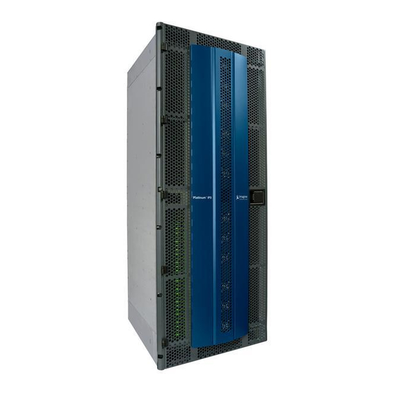
Imagine Platinum IP3 Installation And Operation Manual (315 pages)
Brand:
Imagine
| Category:
Network Router
| Size: 17 MB
Table of Contents
Contact Information
2
Publication Information
2
Table of Contents
3
Preface
14
Manual Information
14
Purpose
14
Audience
14
Revision History
14
Obtaining Documents
15
Unpacking/Shipping Information
15
Unpacking a Product
15
Returning a Product
15
Safety
16
Standards
16
Waste from Electrical and Electronic Equipment (WEEE) Compliance
16
Introduction
18
Platinum IP3 Overview
18
Product Description
18
Platinum IP3 28 RU (PX-FR-28) and 15 RU (PX-FR-15) Frames
18
Features
19
Platinum IP3 Architecture
20
Removing the Frame Door
21
Frame Architecture
23
28 RU Platinum IP3 Front View
23
RU Platinum IP3 Front View
24
28 RU Platinum IP3 Rear View
25
RU Platinum IP3 Rear View
26
28 RU Platinum IP3 Frame Architecture
27
RU Platinum IP3 Frame Architecture
28
Platinum IP3 Physical Specifications
28
Frame Modules
29
Power Consumption
31
Power Consumption of Frame and Input/Output Modules
31
Platinum IP3 Power and Temperature Specifications
32
Expansion Overview
33
Expansion Setup
33
System Expansion
35
Alarms and Leds
37
Control Features
37
Poe
37
Modules
38
Modules Overview
38
Input and Output Modules
38
List of Supported Input and Output Modules
39
Rear Connectors
40
Output Rear Connectors
40
Input Rear Connectors
40
Expansion Modules
40
Crosspoint Modules
40
Monitoring Modules
41
Output Monitoring Modules
41
Multiviewer Modules
41
Resource Module (PX-RES)
42
Resource Module (PX-RES) Overview
42
PX-RES in a Platinum Frame
42
PX-RES Parameters and Upgrades
44
PX-RES Redundancy
44
Communications Back Panel (PX-CBP)
45
User Interfaces
46
Ethernet Ports
46
Sync Ports
47
Alarm Port
48
LTC Bi-Directional Port
48
Leds
48
Fuses
50
DIP Switches
51
XY Ports
51
Serial Ports
51
Resource Card Synchronization
53
Active and Standby Determination
53
Sync Notes
53
Switch Triggering
54
Alarms
56
Power Consumption
56
Installation
56
Alarm Expansion Module (PX-ALARM)
57
PX-ALARM Components
58
Controlling Fan Speed
59
Reporting Alarms and Fan Failures
59
Power Supply Status
59
Power Supply Zone Redundancy
61
GPI Input Alarms
61
GPI Output Alarms (User Configurable Alarms)
62
Fan Failure Alarm
62
General Purpose Interface (GPI)
63
Micro-Dsub Connector Pinouts
64
Parameters
64
PX-ALARM-DATA Parameters
64
PX-ALARM-ATDM Parameters
65
Status and Alarm Leds
66
Failsafe Upgrade
66
Power Consumption
67
Output Monitoring Modules
68
PX-HSRAEC-OM Output Monitoring Module
68
Notes
68
Controllable Parameters
70
Video Crosspoint Module (PX-576X1024-3G/PX-288X512-3G)
72
RU Video Crosspoint Module Location in the Frame
74
Extracting the Video Crosspoint from the 28 RU Frame
75
Putting the Video Crosspoint Back into the 28 RU Frame
78
RU Video Crosspoint Module Location in the Frame
79
Video Crosspoint Module Parameters
80
LED Indicators on Video Crosspoint Module
81
Fuses on the Video Crosspoint Module
82
Power Consumption
83
Audio TDM Crosspoint Module (PX-ATDM64-X28)
84
Audio TDM Crosspoint Module (PX-ATDM64-X28) Location in the IP3 Frame
86
Fuses on the PX-ATDM64-X28
88
DIP Switches on the PX-ATDM64-X28
89
Fans on the Audio TDM Crosspoint Module (PX-ATDM64-X28)
90
Instructions to Replace the Fan Blowers
91
Sync References
91
PX-ATDM64-X28 Block Diagram
91
Functionality
92
16/20/24 Bit Audio Processing
92
Transitions
92
Quiet Switching
92
Synchronous Switching
92
Asynchronous Signals
92
Level Adjustment
92
Sample Rate Conversion (SRC)
92
Tone Generator
93
Polarity Reversal
93
Channels Swapping and Summing
93
Redundancy
93
Frame Expansion
93
LED Indicators
94
Hardware Connections for Audio Expansion
95
Audio Expansion Connection Status in the Web UI
97
PX-ATDM64-X28 Parameters
98
Firmware Upgrade
99
Power Consumption
100
Frame Parameters
101
Frame
102
Px-Res
102
Video Crosspoint
104
TDM Crosspoint
105
Sync
105
Sync Notes
107
Power Supplies
107
Ethernet Ports
108
Serial Ports
110
Input Modules (PX-IB)
111
PX-IB Input Module General Overview
111
PX-IB Input Options
111
PX-IB Expansion
112
Inserting Input Modules into the Platinum IP3 Frame
112
Failsafe Mode
113
Signal Presence and Leds
113
Module Leds
113
System Leds
113
Controllable Parameters
115
Parameter Notes
115
(Module) Root Level Parameters
115
Input Parameters
116
Specifications
119
Technical Specifications
119
Capacity
119
Output Modules (PX-OB)
120
PX-OB Output Module General Overview
120
PX-OB Output Options
120
PX-OB Expansion
121
Inserting Output Modules into the Platinum IP3 Frame
121
Failsafe Mode
121
Signal Presence and Leds
122
System Leds
122
Module Leds
123
Controllable Parameters
123
Parameter Notes
123
(Module) Root Level Parameters
124
Output Parameters
125
Specifications
126
Technical Specifications
126
Capacity
127
Digital Video Modules
128
PX-HSR9C-IBG Input Module
129
Power Consumption
129
PX-HSR9O-IBG Input Module
129
Power Consumption
130
PX-HSR9C-IBG/PX-HSR9O-IBG Parametric Control
130
PX-HSR9C1D-IBG Input Module
131
Power Consumption
131
PX-HSR9O1D-IBG Input Module
131
Power Consumption
132
PX-HSR1C1D-IBG Input Module
132
PX-HSR16C-OBG Output Module
133
Power Consumption
133
PX-HSR16O-OBG Output Module
134
Power Consumption
134
PX-HSR16C-OBG/PX-HSR16O-OBG-IBG Parametric Control
134
PX-HSR8O2D-OBG Output Module
135
Power Consumption
135
PX-HSR8C2D-OBG Output Module
136
Power Consumption
136
PX-HSR8C2D-OBG/PX-HSR8O2D-OBG Parametric Control
137
PX-HSR1D2D-OBG Output Module
137
Power Consumption
138
PX-HSR1D2D-OBG Output Module
138
PX-UCIP Uncompressed Video over IP Modules
139
Frame Synchronizer and Demultiplexing Input Modules (PT-FSDMX-IBG/PT- FSDMXO-IBG, PT-FSDX8C1D-IBG, PT-FSDMX8O1D-IBG)
140
Back Module Variants
141
Electrical/Bnc Back Module (PT-FSDMX-IBG)
142
Optical/Sfp Back Module (PT-FSDMXO-IBG)
142
Electrical Back Module (HD-BNC) with Densishield (PT-FSDX8C1D-IBG)
143
Optical Back Module (SFP) with Densishield (PT-FSDX8O1D-IBG)
144
Specifications
144
Equalization Information for PT-FSDX8C1D-IBG
145
Video Processing Features
146
Video Processing Notes
146
Audio Processing Features
147
Audio Processing Notes and Restrictions
147
Audio Order of Operations
147
Sample Rate Conversion
148
Quiet Audio Transitions
148
PT-FSDMX-IBG Licensing
148
PT-FSDMX-IBG Without Frame Sync Option
148
PT-FSDMX-IBG with Frame Sync Option
149
PT-FSDMX-IBG Controllable Parameters
150
General Parameters
150
Genlock Parameters
151
Input Parameters
151
Notes
156
LED Indicators
160
Power-Up Sequence
160
Firmware Upgrade and Backup Image
161
PX-HSRMX-OBG Frame Sync and Mux Output Module
162
PX-HSR8CMX8C-OBG Electrical Output Module
163
PX-HSR8OMX8O-OBG Optical Output Module
163
PX-HSRMX8C2D-OBG Electrical Module with Densishield
163
PX-HSRMX8O2D-OBG Optical Module with Densishield
164
PX-HSRMX-OBG Operation Modes
164
MUX Only Mode (Without Frame Sync License)
164
Frame Sync Mode
165
PX-HSRMX-OBG Features
166
Audio Processing
167
Video Processing
168
Quiet Audio Switching
169
PX-HSRMX-OBG Specifications
170
Electrical Output (Back Module with 16 HD-Bncs)
170
Electrical Output (Back Module with Densishield)
170
Optical Output (Fiber Back Modules with Sfps)
171
Electrical Input (Back Module with Densishield)
171
PX-HSRMX-OBG Operation
171
Power-Up Sequence
171
Firmware Upgrade and Backup Image
171
LED Indicators
172
Jumpers and DIP Switches
172
Failsafe Module Upgrade
172
Power Consumption
172
Functional Block Diagram
173
PX-HSRMX-OBG Controllable Parameters
174
General Parameters
174
Genlock Parameters
175
Processed Outputs
176
Unprocessed Outputs
183
Notes
184
Multichannel Audio Digital Interface (MADI) Modules
191
MADI Input Module (PT-MADI4X-IBG)
192
Variants
193
Controlling the MADI Input Module through the Controller
194
TDM Mapping
195
MADI Audio Formats
198
Input Specifications
200
Input Power Consumption
200
PT-MADI4X-IBG Parameters
201
MADI Output Module PT-MADI4X-OBG
203
Variants
203
Controlling the MADI Output Module through the Controller
205
Reference Locking
205
TDM Input
206
TDM Output Mapping
207
Output Specifications
207
Output Power Consumption
208
PT-MADI4X-OBG Parameters
208
Analog/Digital Audio Converter Modules with TDM
212
Audio A/D Input Modules with TDM Capability (PT-ADCT-IB)
212
Operation
212
Analog Inputs
213
Operating Modes
214
Installation
215
Control
215
Controllable Parameters
215
Functional Block Diagram
218
Pinout Diagram
219
Specifications
219
Power Consumption
221
AES to Analog Audio Converter Output Modules with TDM Capability (PT-DACT-OB)
222
Operation
222
Installation
223
Control
223
Controllable Parameters
224
Functional Block Diagram
226
Pinout Diagram
227
Specifications
228
Power Consumption
229
AES Balanced/Coaxial Modules with TDM Capability
230
AES Balanced/Coaxial Input Modules with TDM Capability (PT-AEBT-IB/PT-AECT-IB)
230
Operation
230
Installation
232
Control
232
Controllable Parameters
233
Functional Block Diagram
234
Pinout Diagram
235
Specifications
236
Power Consumption
237
AES Balanced/Coaxial Output Modules with TDM Capability(PT-AEBT-OB/PT-AECT-OB)
237
Operation
237
Installation
239
Control
239
Controllable Parameters
240
Functional Block Diagram
241
Pinout Diagram
242
Specifications
243
Power Consumption
244
Analog Composite Video Modules
245
Analog Video to SDI Decoder Input Modules (PT-DEC-IB)
245
Operation
245
Installation
247
Control
247
Controllable Parameters
247
Functional Block Diagram
249
Specifications
249
Power Consumption
250
SD to Analog Video Encoder Modules (PT-ENC-OB)
250
Operation
250
Installation
251
Control
252
Controllable Parameters
252
Functional Block Diagram
254
Specifications
255
Power Consumption
255
Platinum SX Hybrid Multiviewer Modules
256
Platinum SX Hybrid Modules in 15/28 RU Frames
258
Platinum SX Hybrid Back Module
259
Inserting Platinum SX Hybrid Modules into a Frame
260
Configuring the Platinum SX Hybrid Module
261
Platinum SX Pro Multiviewer Modules
262
1500 Watt Power Supply and External Power Supply Frame
263
Power Supplies (PX-PS)
263
Power Supply Modes
264
Power Supplies in a 28 RU Frame
264
Power Supplies in a 15 RU Frame
265
External Power Supply Frame (PX-FR-EXPS)
265
Required Equipment
266
Power Cables
266
Power Cable Installation Steps (for PX-FR-EXPS to PX-FR-28/PX-FR-15)
266
Installing Power Supplies
270
Power Zones
272
Power Zones for a 28 RU Frame
272
Power Zones for a 15 RU Frame
274
Power Distribution Zones
275
Power Distribution Modules
277
Top Power Distribution Module (PX-PD-TOP)
277
Bottom Power Distribution Module (PX-PD-BOT)
280
Power Supply Specs, Leds, and Pinouts
281
Power Supply Mechanical Specification
281
Power Supply Electrical Specification
282
Power Supply LED Operation
283
Power Connector Pinout
284
PX-FRONT-FAN and PX-REAR-FAN Modules
285
Front Fan Module
285
Front Fan Leds
287
Front Fans Status in the Web UI
289
Rear Fan Module
289
Rear Fans Status in the Web UI
291
Servicing the Fans
291
Replacing a Front Fan Module
291
Replacing an Individual Front Fan
293
Replacing a Rear Fan
294
Fuses
295
Fuses on Front Fan Modules
295
Fuses on Rear Fan Adapter Boards
296
Power Consumption
297
Module Leds
298
Card Edge LED Diagnostics
298
LED Labels
298
LED States
298
Input Module Leds
299
Input 1 and Input 2
299
Input 3, Input 4, Input 5
299
Input 6, Input 7, Input 8, Input 9
299
Output Module Leds
300
Output 1 - Output 6
300
Output 7, Output 8, Output 9
300
Output 13, Output 14, Output 15, Output 16
300
Module Interconnect (PX-BP-28/PX-BP-15)
302
PX-BP-28/PX-BP-15 Module Slots
302
Fuses on the Module Interconnect (PX-BP-28)
303
Fuses on the Module Interconnect (PX-BP-15)
307
Module Interconnect Installation
309
Auxiliary Module (PX-AUX)
310
PX-AUX Fuses
311
PX-AUX Block Diagram
312
Sync Module Interconnect (PX-SYNC-MI)
313
Power Adapter Module (PX-PWR-ADPTR)
314
Fuses on the Power Adapter PX-PWR-ADPTR
315
Advertisement
Advertisement
Related Products
Imagine Platinum VX
Imagine IPA6800+
Imagine Platinum Predator II-GX 2RU
Imagine Platinum Predator II ZP2-HD4-GX
Imagine Platinum Predator II ZP2-HD8-GX
Imagine Platinum Predator II ZP2-HD12-GX
Imagine Platinum Predator II ZP2-HD16-GX
Imagine Platinum Predator II ZP2-HD20-GX
Imagine Platinum Predator II ZP2-HD24-GX
Imagine Platinum Predator II ZP2-HD32-GX
Imagine Categories
Media Converter
Amplifier
Monitor
DVD Player
Clock
More Imagine Manuals
Login
Sign In
OR
Sign in with Facebook
Sign in with Google
Upload manual
Upload from disk
Upload from URL