
Related Manuals for Imagine Platinum IP3

Summary of Contents for Imagine Platinum IP3
- Page 1 Installation and Operation Manual Platinum™ IP3 28 RU and 15 RU Frame and Modules September 2016 Edition I...
-
Page 2: Publication Information
Imagine Communications reserves the right, without notice to make such changes in equipment, design, specifications, components, or documentation as progress may warrant to improve the performance of the product. -
Page 3: Table Of Contents
Waste from Electrical and Electronic Equipment (WEEE) Compliance ..........16 Introduction ......................18 Platinum IP3 Overview ........................... 18 Product Description ..........................18 Platinum IP3 28 RU (PX-FR-28) and 15 RU (PX-FR-15) Frames ............18 Features .............................. 19 Platinum IP3 Architecture ........................20 Removing the Frame Door ......................... 21 Frame Architecture .......................... - Page 4 Serial Ports............................51 Resource Card Synchronization ......................53 Active and Standby Determination ....................53 Sync Notes ............................53 Switch Triggering ............................ 54 Alarms ..............................56 Power Consumption ..........................56 © 2016 Imagine Communications Corp. Proprietary and Confidential. September 2016 | Page 4...
- Page 5 Audio TDM Crosspoint Module (PX-ATDM64-X28) Location in the IP3 Frame ........86 Fuses on the PX-ATDM64-X28 ........................ 88 DIP Switches on the PX-ATDM64-X28 ....................89 Fans on the Audio TDM Crosspoint Module (PX-ATDM64-X28) ............90 © 2016 Imagine Communications Corp. Proprietary and Confidential. September 2016 | Page 5...
- Page 6 Input Modules (PX-IB) ..................111 PX-IB Input Module General Overview....................111 PX-IB Input Options .......................... 111 PX-IB Expansion ..........................112 Inserting Input Modules into the Platinum IP3 frame................112 Failsafe Mode ........................... 113 © 2016 Imagine Communications Corp. Proprietary and Confidential.
- Page 7 Output Modules (PX-OB) ................... 120 PX-OB Output Module General Overview .................... 120 PX-OB Output Options........................120 PX-OB Expansion ..........................121 Inserting Output Modules into the Platinum IP3 frame ............... 121 Failsafe Mode ........................... 121 Signal Presence and LEDs ........................122 System LEDs ............................122 Module LEDs .............................
- Page 8 PT-FSDMX-IBG with Frame Sync Option ..................149 PT-FSDMX-IBG Controllable Parameters ....................150 General Parameters ......................... 150 Genlock Parameters ......................... 151 Input Parameters ..........................151 Notes ..............................156 © 2016 Imagine Communications Corp. Proprietary and Confidential. September 2016 | Page 8...
- Page 9 Multichannel Audio Digital Interface (MADI) Modules ........191 MADI Input Module (PT-MADI4X-IBG) ....................192 Variants ............................193 Controlling the MADI Input Module through the Controller ............194 © 2016 Imagine Communications Corp. Proprietary and Confidential. September 2016 | Page 9...
- Page 10 AES Balanced/Coaxial Modules with TDM Capability ......... 230 AES Balanced/Coaxial Input Modules with TDM Capability (PT-AEBT-IB/PT-AECT-IB) ......230 Operation ............................230 Installation ............................232 Control .............................. 232 © 2016 Imagine Communications Corp. Proprietary and Confidential. September 2016 | Page 10...
- Page 11 Platinum SX Hybrid Back Module ......................259 Inserting Platinum SX Hybrid Modules into a Frame ................260 Configuring the Platinum SX Hybrid Module ..................261 Platinum SX Pro Multiviewer Modules ............... 262 © 2016 Imagine Communications Corp. Proprietary and Confidential. September 2016 | Page 11...
- Page 12 Fuses on Front Fan Modules ......................295 Fuses on Rear Fan Adapter Boards ....................296 Power Consumption ..........................297 Module LEDs ...................... 298 Card Edge LED Diagnostics ........................298 © 2016 Imagine Communications Corp. Proprietary and Confidential. September 2016 | Page 12...
- Page 13 PX-AUX Fuses ............................311 PX-AUX Block Diagram .......................... 312 Sync Module Interconnect (PX-SYNC-MI) ............313 Power Adapter Module (PX-PWR-ADPTR) ............314 Fuses on the Power Adapter PX-PWR-ADPTR ..................315 © 2016 Imagine Communications Corp. Proprietary and Confidential. September 2016 | Page 13...
-
Page 14: Preface
This manual details the features, installation, operation, maintenance, and specifications for the Platinum IP3. Audience This manual is written for engineers, technicians, and operators responsible for installation, setup, maintenance, and/or operation of the Platinum IP3. Revision History Edition Date Comments... -
Page 15: Obtaining Documents
Ship products back to us for servicing prepaid and, if possible, in the original packaging material. If the product is still within the warranty period, we will return the product prepaid after servicing. © 2016 Imagine Communications Corp. Proprietary and Confidential. -
Page 16: Safety
(Some EU member states may have different deadlines.) © 2016 Imagine Communications Corp. Proprietary and Confidential. September 2016 | Page 16... - Page 17 Contact your local sales representative for information on returning these products for recycling. Equipment that complies with the EU directive will be marked with a WEEE-compliant emblem. Figure 1: WEEE Compliance Emblem © 2016 Imagine Communications Corp. Proprietary and Confidential. September 2016 | Page 17...
-
Page 18: Introduction
Platinum IP3 28 RU (PX-FR-28) and 15 RU (PX-FR-15) Frames The flagship frame in the Platinum IP3 system is a 28RU frame, featuring 576 wideband video inputs distributed across 64 modular slots, and 1024 wideband video outputs distributed across 64 modular slots. -
Page 19: Features
Installation and Operation Manual Introduction The Platinum IP3 15 RU is a compact version of the larger Platinum IP3 28 RU high-performance router, delivering the same integrated routing and processing capabilities in a space-saving 288x512 form factor. This provides mobile and other production environments with significant cost-, space- and power-efficiency improvements. -
Page 20: Platinum Ip3 Architecture
– one for outputs distribution and a second for input distribution or four cables if redundancy is desired. With the Platinum IP3's Audio Expansion option, a two frame system is fully non-blocking, meaning that audio inputs (embedded or discrete) in frame one can be routed to any output in frame two. -
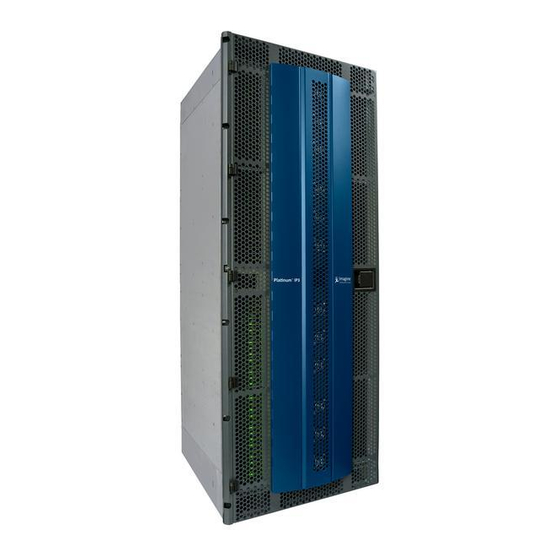
Page 21: Removing The Frame Door
While pressing in the chrome locking pin, lift the door off the hinge and remove. Figure 2: 28 RU IP3 Frame and close up of locking pin © 2016 Imagine Communications Corp. Proprietary and Confidential. September 2016 | Page 21... - Page 22 Platinum™ IP3 Installation and Operation Manual Introduction Figure 3: 15 RU IP3 Frame and close up of locking pin © 2016 Imagine Communications Corp. Proprietary and Confidential. September 2016 | Page 22...
-
Page 23: Frame Architecture
Platinum™ IP3 Installation and Operation Manual Introduction Frame Architecture 28 RU Platinum IP3 Front View Power Supplies Power Supplies Video Crosspoint 1 Outputs 1-256 Inputs 1-144 Front Fans MI Backplane Outputs 257-512 Inputs 145-288 PT-SYNC 1&2 Audio TDM Crosspoint 1&2 Resource Modules (PX-RES) 1&2... -
Page 24: Ru Platinum Ip3 Front View
Platinum™ IP3 Installation and Operation Manual Introduction 15 RU Platinum IP3 Front View Power Supplies Power Supplies Inputs 1-144 Outputs 1-256 Front Fans Video Crosspoint 1 Video Crosspoint 2 Inputs 145-288 Outputs 257-512 PT-SYNC 1&2 Audio TDM Crosspoint 1&2 Resource Modules (PX-RES) 1&2... -
Page 25: 28 Ru Platinum Ip3 Rear View
Important: Rear Filler plates (required to maintain proper airflow in the frame and for Electro-Magnetic compliance) are installed by Imagine Communications Manufacturing to block the empty I/O slots. 1 slot, 8 slot, and 16 slot plates are available. If a Rear Filler plate is removed to install a new module, the empty slots should be closed with a Filler plate. -
Page 26: Ru Platinum Ip3 Rear View
Platinum™ IP3 Installation and Operation Manual Introduction 15 RU Platinum IP3 Rear View Rear Fans AC/DC Rear Panel Input Back Output Back Modules Modules Alarm and Communications Expansion Module Back Panel Figure 7: 15 RU Frame Rear View © 2016 Imagine Communications Corp. -
Page 27: 28 Ru Platinum Ip3 Frame Architecture
Platinum™ IP3 Installation and Operation Manual Introduction 28 RU Platinum IP3 Frame Architecture Figure 8: Platinum IP3 28 RU Frame Architecture © 2016 Imagine Communications Corp. Proprietary and Confidential. September 2016 | Page 27... -
Page 28: Ru Platinum Ip3 Frame Architecture
Platinum™ IP3 Installation and Operation Manual Introduction 15 RU Platinum IP3 Frame Architecture Figure 9: Platinum IP3 15 RU Frame Architecture Platinum IP3 Physical Specifications Table 2: Platinum IP3 Physical Specifications PLATINUM IP3 PLATINUM Architecture 28 RU 15 RU 28 RU... -
Page 29: Frame Modules
Redundant Power Supply Redundant Resource Module Redundant Sync Options Redundant Crosspoint Frame Modules The Platinum IP3 frame is divided into sections for Input, Output, Crosspoint, and Control modules. Frame modular components include the following items: Slots in Slots in Type... - Page 30 (28 RU and 15 RU) See Rear Fan Module (on page 289) PX-AUX Auxiliary Board Auxiliary board for providing power to Front Fan modules. See Auxiliary Module (PX-AUX) (on page 310). © 2016 Imagine Communications Corp. Proprietary and Confidential. September 2016 | Page 30...
-
Page 31: Power Consumption
PX-HSR16O-OBG 21.9W 0.43W 22.33W Digital Video Optical Input Module Digital Video Optical Input PX-HSR8O2DS-OBG 0.43W 18.43W Module with DensiShield Digital Video Input Module PX-HSR8C2DS-OBG 14.1W 0.43W 14.53W © 2016 Imagine Communications Corp. Proprietary and Confidential. September 2016 | Page 31... -
Page 32: Platinum Ip3 Power And Temperature Specifications
PT-ENC-OB Platinum IP3 Power and Temperature Specifications The specifications in this section are for the Platinum IP3 frame and system-wide components. Specifications for individual modules are listed with their detailed descriptions. Specifications and designs are subject to change without notice. -
Page 33: Expansion Overview
Installation and Operation Manual Introduction Expansion Overview The Platinum IP3 Frame, when used in isolation, provides a 576x1024 (28 RU) or 288x512 matrix (15 RU) with 9 Inputs per Input Slot and 16 Outputs per Output Slot. Video Matrix Expansion Video frame expansion is achieved via the secondary switching capabilities of the output card. - Page 34 Follow the wizard to create a Video Device Type (for example, HD video), and then add another Video based Connection Type to it (for example, HD Video again). Figure 10: Example of Device Type with 2 Video channels © 2016 Imagine Communications Corp. Proprietary and Confidential. September 2016 | Page 34...
-
Page 35: System Expansion
3. Select the frame to connect it to from the second Frame drop-down list 4. Click the Add Connection button Figure 11: System Configuration - System Expansion © 2016 Imagine Communications Corp. Proprietary and Confidential. September 2016 | Page 35... - Page 36 In addition to the Audio expansion definition in the UI, ensure you make the required physical connections - see Hardware Connections for Audio Expansion (on page 95). © 2016 Imagine Communications Corp. Proprietary and Confidential. September 2016 | Page 36...
-
Page 37: Alarms And Leds
Platinum IP3 router. This means that switches will occur in a timely manner, which allows the router to be used in broadcast facilities where timing is crucial to the success of the facility. -
Page 38: Modules
See List of Supported Input and Output Modules (on page 39) for a specific list of modules. Note: Platinum IP3 modules can be damaged if they are plugged into the wrong back modules or wrong slot. Care should be exercised when plugging modules into the frame. -
Page 39: List Of Supported Input And Output Modules
Platinum™ IP3 Installation and Operation Manual Modules List of Supported Input and Output Modules Table 5: Platinum IP3 Input and Output Modules Functional Type Input Module Output Module Multichannel Audio Digital PT-MADI4C-IBG PT-MADI4C-OBG Interface (MADI) Modules MADI Electrical Input Module... -
Page 40: Rear Connectors
9 HDBNC/1 HDBNC output SD/HD/3G Matrix Expansion back panel Expansion Modules The Platinum IP3 frame supports expansion modules to provide TDM and Data Fabric interconnect with a second frame when operating in expansion mode. Expansion is achieved using output modules. There must be corresponding output cards in the primary and expansion frames for inputs to be accessible. -
Page 41: Monitoring Modules
Platinum™ IP3 Installation and Operation Manual Modules Monitoring Modules Output Monitoring Modules The Platinum IP3 router supports one optional Output Monitoring module. Table 9: Output Monitoring Modules Module Description PX-HSRAEC-OM Output Monitoring Module See PX-HSRAEC-OM Output Monitoring Module (on page 68) -
Page 42: Resource Module (Px-Res)
Resource Module (PX-RES) Resource Module (PX-RES) Overview The PX-RES Resource Module serves as the central control point for the Platinum IP3 frame and all modules that reside in the frame. The PX-RES is a control module with software and hardware components that control communications between the different processing modules (Input, Output, Crosspoint, Fans, Power Supplies) in an IP3 frame. - Page 43 (PT) Output Modules PX-HSR16C-OBG PT-AEBT-OB PX-HSR8C2D-OBG PM-AEBT-OB PX-HSR8O2D-OBG PT-AECT-OB PX-HSR16O-OBG PM-AECT-OB PX-HSRSXP2D-OBG PT-DACT-OB PX-HSRMX8C2D-OBG PM-DACT-OB PX-HSRMX8O2D-OBG PT-ENC-OB PX-HSR8CMX8C-OBG PM-ENC-OB PX-HSR8OMX8O-OBG PT-HSR-OB+ PM-HSR-OB+ PT-HSR-OBG+ PM-HSR-OBG+/ PT-HSRO-OBG+ PT-HSRMX8C-OBG PT-HSRMX8O-OBG © 2016 Imagine Communications Corp. Proprietary and Confidential. September 2016 | Page 43...
-
Page 44: Px-Res Parameters And Upgrades
For details, refer the Platinum IP3 Controller User Manual. PX-RES Redundancy Each Platinum IP3 frame can have up to two PX-RES modules operating redundantly. If one module detects failure of the other, it switches over control and continues router operation. -
Page 45: Communications Back Panel (Px-Cbp)
One Alarm Port (on page 48) Two Serial Ports (on page 51) Two XY Ports (on page 51) with loop through One LTC Bi-Directional Port (on page 48) © 2016 Imagine Communications Corp. Proprietary and Confidential. September 2016 | Page 45... -
Page 46: User Interfaces
Changing the Default IP Address of the Rear Ethernet Ports Ethernet settings can be changed via the Controller. To do this: 1. Launch the Platinum IP3 Controller UI in a web browser, select your Platinum IP3 Frame, and click Go to Device. -
Page 47: Sync Ports
Input/Output modules. These Sync Distribution Modules also support redundant operation, and have the capability to seamlessly switch over when the redundant module is removed. © 2016 Imagine Communications Corp. Proprietary and Confidential. September 2016 | Page 47... -
Page 48: Alarm Port
Flashing Amber PX-RES is in progress. ALARM1 LED flashes amber when a user sets the frame identifying LLDC parameter ACTRES Green On for the active PX-RES module © 2016 Imagine Communications Corp. Proprietary and Confidential. September 2016 | Page 48... - Page 49 There are nine LEDs behind the Card-edge Ejector handle. All of these LEDs should be ON when the POWER LED is ON. If any one of them is OFF, it indicates a problem with a power circuit on the module. Figure 16: Power LEDs © 2016 Imagine Communications Corp. Proprietary and Confidential. September 2016 | Page 49...
-
Page 50: Fuses
Figure 17: Fuses on the PX-RES Resource Module Fuses on the PX-RES Resource Module Fuse Name Fuse Type Fuse Rating Part Number Slowblow 2 Amps 127-100001Q00 Slowblow 2 Amps 127-100001Q00 Slowblow 2 Amps 127-100001Q00 © 2016 Imagine Communications Corp. Proprietary and Confidential. September 2016 | Page 50... -
Page 51: Dip Switches
XY Ports Note: The two XY ports on the rear of the Platinum IP3 frame are not used or supported in the initial release of Platinum IP3. If coaxial XY protocol is required in a system, the Imagine Communications EDGE Router Protocol Translator can be used to interface coaxial XY networks with the Platinum IP3 Control System. - Page 52 Received data shield Ra (Rx-) Received data Ta (Tx-) (twisted pair) Rb (Rx+) Tb (Tx+) Transmitted data shield Transmitted data shield Frame ground Frame ground (Not connected) (Not connected) © 2016 Imagine Communications Corp. Proprietary and Confidential. September 2016 | Page 52...
-
Page 53: Resource Card Synchronization
If Sync Mode is set to Standard, the Output Standard parameter can be used to specify the standard to use as the reference signal. The output switches relative to the specified reference. © 2016 Imagine Communications Corp. Proprietary and Confidential. -
Page 54: Switch Triggering
1920x1080/50I Line 7 1920x1080/30P Line 7 1920x1080/30P /1.001 Line 7 1920x1080/25P Line 7 1920x1080/24P Line 7 1920x1080/24PsF Line 7 1920x1080/24P /1.001 Line 7 1920x1080/24PsF /1.001 Line 7 © 2016 Imagine Communications Corp. Proprietary and Confidential. September 2016 | Page 54... - Page 55 960x483/60I /1.001 Line 10 (alias of Analog 525/60 /1.001) 1920x1080/30PsF Line 7 (alias of 1080/60I) 1920x1080/30PsF /1.001 Line 7 (alias of 1080/59.94I) 1920x1080/25PsF Line 7 (alias of 1080/50I) © 2016 Imagine Communications Corp. Proprietary and Confidential. September 2016 | Page 55...
-
Page 56: Alarms
2 (Primary and Secondary) Installation All communications back panel modules are installed at Imagine Communications' manufacturing facility The module is replaceable, however, all control and communication with the frame will be lost when it is replaced. If you need to upgrade or replace this module, please contact our Customer Service Department. -
Page 57: Alarm Expansion Module (Px-Alarm)
The PX-ALARM module reports the status of the Rear Fans (Tachometer reading), Internal and External Power Supply Alarms, and GPI Inputs, to the IP3 Controller via the Resource Module (PX-RES), and to LEDs and GPI Outputs on the PX-ALARM (Platinum IP3 frame rear). The PX-ALARM can control four GPI Outputs. -
Page 58: Px-Alarm Components
PX-ALARM-DATA Data Expansion and Alarm Card The Platinum IP3 frame has two rows of connectors for the PX-ALARM module. Each slot consists of one 60-pin and one 140-pin Samtec card-edge connector. The PX-ALARM-DATA card goes into one slot, and the PX-ALARM-ATDM card goes into the other one. Both are assembled as a single module and inserted into the frame. -
Page 59: Controlling Fan Speed
Reporting Alarms and Fan Failures PX-ALARM monitors the status signal of core components and reports any instance of a critical failure. Reporting is done to the Platinum IP3 Controller via the Resource card (PX-RES) and to the GPI Outputs and LEDs. - Page 60 Installation and Operation Manual Alarm Expansion Module (PX-ALARM) External Power Supply frames can be connected to the Platinum IP3 frame via DC power cables. The DC power cables are connected to the Power Adapter boards. The Alarm and I2C signals from the External Power Supplies are routed through the BackPlane/MI to the PX-ALARM-DATA board.
-
Page 61: Power Supply Zone Redundancy
PX-ALARM-DATA module. Note that the UI displays 4 zones even in case of the 15 RU Platinum IP3 frame which has only 2 zones. Zones 3 and 4 will show as N/A for a 15 RU frame. -
Page 62: Gpi Output Alarms (User Configurable Alarms)
If any of the Rear fan modules have a failure: This alarm condition is reported to the Platinum IP3 Controller via the Resource card The FAN ALM LED on the PX-ALARM module is illuminated ... -
Page 63: General Purpose Interface (Gpi)
Normally open; contact shorted with common when alarm does not exist and frame is powered COMMON Reed (Return of the Relay) PX-ALARM CONTROL Figure 22: GPI Outputs Figure 23: Micro DSUB connector pin numbering © 2016 Imagine Communications Corp. Proprietary and Confidential. September 2016 | Page 63... -
Page 64: Micro-Dsub Connector Pinouts
PS Zone Redundancy (1-4) Reports Power Zone redundancy status (Table Parameter) Yes Power Supply Good PS Status (1-16) Reports individual power supply status Failed Not Present © 2016 Imagine Communications Corp. Proprietary and Confidential. September 2016 | Page 64... -
Page 65: Px-Alarm-Atdm Parameters
Reports if the board is experiencing any power issues Yes No TDM Cable Present (1-4) Set to yes if there is a densishield cable plugged in. (Table Parameter) Yes © 2016 Imagine Communications Corp. Proprietary and Confidential. September 2016 | Page 65... -
Page 66: Status And Alarm Leds
Failsafe Upgrade Should the PX-ALARM module get corrupted and the Platinum IP3 Controller cannot update the firmware: Press and hold the Fail Safe A and Fail Safe D for 3 seconds. -
Page 67: Power Consumption
Table 23: PX-ALARM Power Consumption PX-ALARM-ATDM PX-ALARM-DATA PX-ALARM-DATA (No Expansion) (Expansion) 24V Power Rail 0.35W 5V Power Rail 0.35W 0.35W 0.4W Total per Module 2.35W 0.7W 6.4W © 2016 Imagine Communications Corp. Proprietary and Confidential. September 2016 | Page 67... -
Page 68: Output Monitoring Modules
Slot 7 has Video OUT3, OUT4. Each PX-HSRAEC-OM module can only monitor one output at a time from an output card on the same router © 2016 Imagine Communications Corp. Proprietary and Confidential. September 2016 | Page 68... - Page 69 Signal Presence Active signal on this input (green) EXT IN 4 Signal Presence Active signal on this input (green) POWER Power Supply Indicator +24V power rails are operational © 2016 Imagine Communications Corp. Proprietary and Confidential. September 2016 | Page 69...
-
Page 70: Controllable Parameters
Indicates presence of SDI or (Table Parameter) ASI signal. ASI signals will No automatically bypass all processing stages. Yes Audio AES Input Present (Table Parameter) No © 2016 Imagine Communications Corp. Proprietary and Confidential. September 2016 | Page 70... - Page 71 Sync 1 Audio Reference Selects AES reference input for source Sync 2 Sync 3 Sync 4 Yes DARS Input Present No © 2016 Imagine Communications Corp. Proprietary and Confidential. September 2016 | Page 71...
-
Page 72: Video Crosspoint Module (Px-576X1024-3G/Px-288X512-3G)
576x1024-3G/PX-288x512-3G) The PX-576x1024-3G Video Crosspoint Module is the core switching matrix that enables 576x1024 switching within a single Platinum IP3 28 RU frame. The PX-288-512-3G Video Crosspoint Module enables 288x512 switching within a single 15 RU frame. You can switch any of the 288/576 input signals to any of the 512/1024 outputs based on commands from the system control. - Page 73 Platinum™ IP3 Installation and Operation Manual Video Crosspoint Module (PX-576x1024-3G/PX-288x512-3G) Figure 25: PX-288x512-3G Video Crosspoint Module (for 15 RU) © 2016 Imagine Communications Corp. Proprietary and Confidential. September 2016 | Page 73...
-
Page 74: Ru Video Crosspoint Module Location In The Frame
28 RU Video Crosspoint Module Location in the Frame The Platinum IP3 28 RU frame includes two slots for Video Crosspoint modules. The First slot holds the Primary Video Crosspoint Module. The second slot holds an optional Secondary module, which shadows all operations of the active module, so as to allow it to become active in case the primary module is ©... -
Page 75: Extracting The Video Crosspoint From The 28 Ru Frame
Extracting the Video Crosspoint from the 28 RU Frame 1. On the lower extractor, press the back side of the locking pin while pushing the extractor in. 2. After the extractor releases, pull it down. © 2016 Imagine Communications Corp. Proprietary and Confidential. September 2016 | Page 75... - Page 76 4. After the extractor releases, pull it down. 5. While holding back the Fan Module, grasp the upper and lower extractors and pull outward. © 2016 Imagine Communications Corp. Proprietary and Confidential. September 2016 | Page 76...
- Page 77 7. Gently remove the Crosspoint Module ensuring that you support it from the middle rather than the front of the module. © 2016 Imagine Communications Corp. Proprietary and Confidential. September 2016 | Page 77...
-
Page 78: Putting The Video Crosspoint Back Into The 28 Ru Frame
When you need to put the Video Crosspoint Module back into the Frame, note the notch at the bottom that the card should slide into. Also note the notch at the top. © 2016 Imagine Communications Corp. Proprietary and Confidential. September 2016 | Page 78... -
Page 79: Ru Video Crosspoint Module Location In The Frame
(located behind fan module, beside Crosspoint #1) The Platinum IP3 15 RU frame includes two slots for Video Crosspoint modules. The First slot holds the Primary Video Crosspoint Module. The second slot holds an optional Secondary module. The procedure to insert/extract a 15 RU Video Crosspoint is similar to the process for the 28 RU, with some minor differences. -
Page 80: Video Crosspoint Module Parameters
Video Crosspoint Module (PX-576x1024-3G/PX-288x512-3G) Video Crosspoint Module Parameters The Video Crosspoint Module can be accessed and controlled via the web-based Platinum IP3 Controller. Access the Module in the Crosspoint Cards section in the list of Modules, and click Open Module. -
Page 81: Led Indicators On Video Crosspoint Module
Front Fan module indicates which Video Crosspoint is the Active Crosspoint. The ACT XPT LED will be off on the Front Fan module in front of the Standby Crosspoint. © 2016 Imagine Communications Corp. Proprietary and Confidential. September 2016 | Page 81... -
Page 82: Fuses On The Video Crosspoint Module
Video Crosspoint Module (PX-576x1024-3G/PX-288x512-3G) Fuses on the Video Crosspoint Module Table 30: Fuses on the Video Crosspoint Module Fuse Name Fuse Type Fuse Rating Part Number Slowblow 750 mA 127-100004Q00 © 2016 Imagine Communications Corp. Proprietary and Confidential. September 2016 | Page 82... -
Page 83: Power Consumption
2 (Primary and Secondary) Table 32: PX-288x512-3G Power Consumption 24V Power Rail 110W 5V Power Rail 0.1W Total Power 110.1W Modules in Frame 2 (Primary and Secondary) © 2016 Imagine Communications Corp. Proprietary and Confidential. September 2016 | Page 83... -
Page 84: Audio Tdm Crosspoint Module (Px-Atdm64-X28)
It also allows for certain audio effects for a given destination. Platinum and Platinum IP3 Routers support all types of audio including Dolby E and AC3. Since audio processing such as quiet switching and gain controls can cause data corruption with non-PCM audio, Platinum routers support a pass-through mode for these non-PCM sources. - Page 85 (wideband) crosspoint without any processing. The embedded audio, and all ancillary data, is presented at the output exactly as it entered the router. Figure 27: PX-ATDM64-X28 Audio Crosspoint Module © 2016 Imagine Communications Corp. Proprietary and Confidential. September 2016 | Page 85...
-
Page 86: Audio Tdm Crosspoint Module (Px-Atdm64-X28) Location In The Ip3 Frame
Audio TDM Crosspoint Module (PX-ATDM64- X28) Location in the IP3 Frame Audio TDM Crosspoint 1 & 2 Modules Figure 28: Audio TDM Crosspoint Module in a 28 RU Platinum IP3 frame © 2016 Imagine Communications Corp. Proprietary and Confidential. September 2016 | Page 86... - Page 87 Figure 29: Audio TDM Crosspoint Module in a 15 RU Platinum IP3 frame The Platinum IP3 frame includes two slots for Audio TDM Crosspoint modules, for a Primary and Secondary Audio TDM Crosspoint Module. The Secondary module shadows all operations of the Primary module, so as to allow it to become active in case the Primary module is removed or halted due to error.
-
Page 88: Fuses On The Px-Atdm64-X28
Table 33: PX-ATDM64-X28 Fuses Fuse Name Fuse Type Fuse Rating Present on Part Number PSF1 Slowblow 4 Amps 24V power rail 127-100006Q00 Slowblow 0.75 Amps 5V power rail 127-100004Q00 © 2016 Imagine Communications Corp. Proprietary and Confidential. September 2016 | Page 88... -
Page 89: Dip Switches On The Px-Atdm64-X28
Make sure the jumpers are restored to this position after performing a failsafe upgrade. Switch 2, 3 and 4 are reserved for future use. Figure 31: DIP Switches on the PX-ATDM64-X28 Module © 2016 Imagine Communications Corp. Proprietary and Confidential. September 2016 | Page 89... -
Page 90: Fans On The Audio Tdm Crosspoint Module (Px-Atdm64-X28)
Figure 32: Fans on the PX-ATDM64-X28 Table 34: PX-ATDM64-X28 Fan Components Fan Component Part Number Fan Blower 131-100006Q00 Fan Mounting Screws (4-40 3/16) 4-40X3/16 PH_Q Fan Connector P9 Fan Connector P12 © 2016 Imagine Communications Corp. Proprietary and Confidential. September 2016 | Page 90... -
Page 91: Instructions To Replace The Fan Blowers
Audio from each Input slot is routed to both ATDM Crosspoints and Outputs from the ATDM Crosspoints are routed to each Output Slot. Both ATDM Crosspoint receive and process audio signals simultaneously. © 2016 Imagine Communications Corp. Proprietary and Confidential. -
Page 92: Functionality
Input Audio TDM modules. Audio sampled at 32 kHz to 96 kHz can be Sample Rate Converted to 48 kHz and locked to the Digital Audio Reference Signals (DARS) connected to the Platinum IP3 frame. © 2016 Imagine Communications Corp. -
Page 93: Tone Generator
They also provide the ability to average two stereo pairs into a single mono channel. Redundancy There are 2 slots in the Platinum IP3 frame for Audio TDM Crosspoint Modules, for the primary and secondary modules. The redundant module becomes active within one video frame of an error occurring or with removal of the active board. -
Page 94: Led Indicators
When lit, this indicates that this is the Main Crosspoint PRIMARY Green When lit, this indicates the Audio TDM Crosspoint is driving audio outputs. Figure 34: LEDs on the PX_ATDM64_X28 Crosspoint Module © 2016 Imagine Communications Corp. Proprietary and Confidential. September 2016 | Page 94... -
Page 95: Hardware Connections For Audio Expansion
4. Frame 2, TDM XPT OUT2 > Frame 1, TDM XPT IN2 Connect a Densishield cable from the OUT2 of the bottom PX-ATDM64-X28 module in Frame 2 to the IN2 of the bottom PX-ATDM64-X28 module in Frame 1 © 2016 Imagine Communications Corp. Proprietary and Confidential. September 2016 | Page 95... - Page 96 Platinum™ IP3 Installation and Operation Manual Audio TDM Crosspoint Module (PX-ATDM64-X28) FRAME 1 FRAME 2 PX-ALARM-ATDM Module PX-ALARM-ATDM Module © 2016 Imagine Communications Corp. Proprietary and Confidential. September 2016 | Page 96...
-
Page 97: Audio Expansion Connection Status In The Web Ui
Audio Expansion Connection Status in the Web UI Open the PX-ATDM64-X28 Audio TDM Crosspoint Module from the list of modules by clicking the Open Module button against it. © 2016 Imagine Communications Corp. Proprietary and Confidential. September 2016 | Page 97... -
Page 98: Px-Atdm64-X28 Parameters
No activity The state of any current upgrades FPGA FPGA Rev The FPGA Revision <String> FPGA Temp The FPGA Temperature <String> FPGA Temp Alarm FPGA Temperature Alarm © 2016 Imagine Communications Corp. Proprietary and Confidential. September 2016 | Page 98... -
Page 99: Firmware Upgrade
5. Once the firmware has been loaded to the repository, go to the IO Module tab 6. Expand details for the frame that contains your module 7. Locate the PX-ATDM64-x28 module under Crosspoint Cards and select it © 2016 Imagine Communications Corp. Proprietary and Confidential. September 2016 | Page 99... -
Page 100: Power Consumption
9. In the Select Firmware dialog, select the version of the firmware to upgrade the module with. Click Power Consumption Table 36: PX-ATDM64-X28 Power Consumption 24V Power Rail 5V Power Rail 0.8W Total Power 55.8W © 2016 Imagine Communications Corp. Proprietary and Confidential. September 2016 | Page 100... -
Page 101: Frame Parameters
TDM Crosspoint (on page 105) Sync (on page 105) Power Supplies (on page 107) Ethernet Ports (on page 108) Serial Ports (on page 110) © 2016 Imagine Communications Corp. Proprietary and Confidential. September 2016 | Page 101... -
Page 102: Frame
PX-RES 1 Serial # Not Present <String> PX-RES 2 Serial # Not Present Active PX-RES 1 Standby Not Present Initializing Configuring © 2016 Imagine Communications Corp. Proprietary and Confidential. September 2016 | Page 102... - Page 103 A string showing the current firmware version of the active PX-RES PX-RES Alternate Version A string showing the firmware version on the alternate bank of the active PX-RES Figure 37: PX-RES Parameters © 2016 Imagine Communications Corp. Proprietary and Confidential. September 2016 | Page 103...
-
Page 104: Video Crosspoint
Failed Active Video Crosspoint 2 Standby Not Present Failed Module1 Select Active Video Crosspoint Module2 Figure 38: Video Crosspoint Parameters © 2016 Imagine Communications Corp. Proprietary and Confidential. September 2016 | Page 104... -
Page 105: Tdm Crosspoint
Figure 39: TDM Crosspoint Parameters Sync The Sync section provides the following parameters: Table 41: Sync Parameters Parameter Type Description/Options Sync Mode Auto, Standard, Advanced (Table Parameter) © 2016 Imagine Communications Corp. Proprietary and Confidential. September 2016 | Page 105... - Page 106 Sync 1 Sync 3 - Source Select Sync 2 Sync 3 Sync 1 Sync 4 - Source Select Sync 2 Sync 4 © 2016 Imagine Communications Corp. Proprietary and Confidential. September 2016 | Page 106...
-
Page 107: Sync Notes
Present 5V Power (15 RU only) Failed Present Bottom Shelf 5V Power (28 RU only) Failed Present Zone 1 24V Power Failed © 2016 Imagine Communications Corp. Proprietary and Confidential. September 2016 | Page 107... -
Page 108: Ethernet Ports
IP address string for the back panel Ethernet connectors 1 and 3 IP Mask 1 IP mask string for the back panel Ethernet connectors 1 and 3 Gateway Address 1 Gateway Address string © 2016 Imagine Communications Corp. Proprietary and Confidential. September 2016 | Page 108... - Page 109 IP Mask 2 IP mask string for the back panel Ethernet connectors 2 and 4 Gateway Address 2 Gateway Address string No Save Ethernet 2 Yes © 2016 Imagine Communications Corp. Proprietary and Confidential. September 2016 | Page 109...
-
Page 110: Serial Ports
57600 115200 1 Port (1-2) Stop Bit 2 None Port (1-2) Parity Odd Even No Save Serial (1-2) Yes © 2016 Imagine Communications Corp. Proprietary and Confidential. September 2016 | Page 110... -
Page 111: Input Modules (Px-Ib)
Input Modules (PX-IB) PX-IB Input Module General Overview The PX-IB is a generic Video Input Module designed for the Platinum IP3 Frame. It supports signals up to 3 Gbps. The PX-IB Input Module accepts digital video signals, equalizes and retimes data streams, detects standards and formats, and distributes signals to the MI backplane to be switched by the crosspoint matrix. -
Page 112: Px-Ib Expansion
Inserting Input Modules into the Platinum IP3 frame Each Input Module may be inserted into, or extracted from, a Platinum IP3 frame while the frame is powered and functioning. The system Controller will recognize the addition or removal of an Input Module from any of the Input Module slots, and will update the change automatically. -
Page 113: Failsafe Mode
Valid Signal present but not locked Solid On Valid Signal present and locked POWER Power Supply indicator Green +24V power rails are operational ACT CTRL Active Control Initializing © 2016 Imagine Communications Corp. Proprietary and Confidential. September 2016 | Page 113... - Page 114 Input on card being used by one or more outputs Note: PX-IB can lock to 270Mbps, 1.5Gbps and 3Gbps video SDI signals. Figure 43: LEDs on PX-IB Input Module © 2016 Imagine Communications Corp. Proprietary and Confidential. September 2016 | Page 114...
-
Page 115: Controllable Parameters
Parameter Notes Parameters can be enabled and/or changed via CCS Navigator or the Platinum IP3 Controller. Parameters marked with the [RO] designator are "read-only." Parameters marked Modules with SFPs Only apply only to optical modules such as PX-HSR9O-IBG Input Module (on page 129). -
Page 116: Input Parameters
The following parameters are displayed: Table 48: Input Parameters Name Description Type Options Yes Signal Presence Reports presence or absence of valid signal No © 2016 Imagine Communications Corp. Proprietary and Confidential. September 2016 | Page 116... - Page 117 3G HD SD Bypass Yes Lock Detect Reports if data is relocked by reclocking stage No © 2016 Imagine Communications Corp. Proprietary and Confidential. September 2016 | Page 117...
- Page 118 Small (400mVpp). EQ Always On EQ Power Save Mode Puts equalizer into power save mode Auto EQ Always Off © 2016 Imagine Communications Corp. Proprietary and Confidential. September 2016 | Page 118...
-
Page 119: Specifications
Table 52: Input Module - Capacity Number of Inputs From rear edge of module Number of Outputs To MI connector To rear edge of module 9 (optional) © 2016 Imagine Communications Corp. Proprietary and Confidential. September 2016 | Page 119... -
Page 120: Output Modules (Px-Ob)
Output Modules (PX-OB) PX-OB Output Module General Overview The PX-OB is a generic, Video Output Module designed for the Platinum IP3 Frame. PX-OB modules recondition SDI video received from crosspoint modules before distributing to various output interfaces - such as standard BNC coaxial cables, HD-BNC coaxial cables, and SFP optical fiber. PX- OB output modules are hot-swappable. -
Page 121: Px-Ob Expansion
Inserting Output Modules into the Platinum IP3 frame Each Output Module may be inserted into, or extracted from, a Platinum IP3 frame while the frame is powered and functioning. The system Controller will recognize the addition or removal of an Output Module from any of the Output Module slots, and will update the change automatically. -
Page 122: Signal Presence And Leds
Both have the ability to be disabled or enabled through the control software. Figure 45: System LEDs on PX-OB Output Module System LEDs There are 3 system indicator LEDs on the front edge of the module: © 2016 Imagine Communications Corp. Proprietary and Confidential. September 2016 | Page 122... -
Page 123: Module Leds
HSR8O2DS-OBG Output Module, PX-HSR8C2DS-OBG Output Module, and PX-HSR1D2D-OBG Output Module (on page 137) Parameters marked Modules with SFPs Only apply only to optical modules such as PX-HSR16O-OBG Output Module. © 2016 Imagine Communications Corp. Proprietary and Confidential. September 2016 | Page 123... -
Page 124: (Module) Root Level Parameters
Sync 1 Sync Select Selects which physical sync port the (Under Module) module uses as a reference Sync 2 Sync 3 Sync 4 © 2016 Imagine Communications Corp. Proprietary and Confidential. September 2016 | Page 124... -
Page 125: Output Parameters
Reports if data is relocked by (Expansion Modules only) reclocking stage No Yes Exp Auto Bypass Sets automatic reclocker (Expansion Modules only) bypass mode No © 2016 Imagine Communications Corp. Proprietary and Confidential. September 2016 | Page 125... -
Page 126: Specifications
800mV +/- 10% Amplitude <10% Overshoot 0V +/- 0.5V DC Offset 270Mb/s: 400-800pS Rise Time 1.485Gb/s: < 135pS 2.97Gb/s: < 135pS © 2016 Imagine Communications Corp. Proprietary and Confidential. September 2016 | Page 126... -
Page 127: Capacity
32 (16 main + 16 redundant) Number of Outputs To rear edge of module 16 (16 single ended or 16 differential or 8 single ended + 8 differential) © 2016 Imagine Communications Corp. Proprietary and Confidential. September 2016 | Page 127... -
Page 128: Digital Video Modules
UCIP module and 2 additional DensiShield connectors for Expansion. When the expansion DensiShield connector is not used for Expansion, it can be connected to a second PX-UCIP module. © 2016 Imagine Communications Corp. Proprietary and Confidential. September 2016 | Page 128... -
Page 129: Px-Hsr9C-Ibg Input Module
The Back Module interfaces with the PX-IB Input module to accept 9 optical inputs. See Input Modules (PX-IB) (on page 111) for details on the PX-IB Input module. © 2016 Imagine Communications Corp. Proprietary and Confidential. September 2016 | Page 129... -
Page 130: Power Consumption
HSR9C-IBG/PX-HSR9O-IBG module (by clicking on it in the list of Input Modules), its parameters are displayed. The total number of PX-HSR9C-IBG/9O modules in the frame is also displayed on the left. © 2016 Imagine Communications Corp. Proprietary and Confidential. September 2016 | Page 130... -
Page 131: Px-Hsr9C1D-Ibg Input Module
The Back Module interfaces with the PX-IB Input module to accept 9 optical inputs. See Input Modules (PX-IB) (on page 111) for details on the PX-IB Input module. © 2016 Imagine Communications Corp. Proprietary and Confidential. September 2016 | Page 131... -
Page 132: Power Consumption
See Input Modules (PX-IB) (on page 111) for details on the PX-IB Input module. Power Consumption Table 65: PX-HSR1C1D-IBG Power Consumption 24V Power Rail 5V Power Rail Total Power © 2016 Imagine Communications Corp. Proprietary and Confidential. September 2016 | Page 132... -
Page 133: Px-Hsr16C-Obg Output Module
See Output Modules (PX-OB) (see "Input Modules (PX-IB)" on page 111) for details on the PX-OB Output module. Power Consumption Table 66: PX-HSR16C-OBG Power Consumption 24V Power Rail 11.7W 5V Power Rail 0.43W Total Power 12.13W © 2016 Imagine Communications Corp. Proprietary and Confidential. September 2016 | Page 133... -
Page 134: Px-Hsr16O-Obg Output Module
PX-HSR16C-OBG/PX-HSR16O-OBG module (by clicking on it in the list of Output Modules), its parameters are displayed. The total number of PX-HSR16C-OBG/PX-HSR16O-OBG modules in the frame is also displayed on the left. © 2016 Imagine Communications Corp. Proprietary and Confidential. September 2016 | Page 134... -
Page 135: Px-Hsr8O2D-Obg Output Module
8 optical/electrical). See Output Modules (PX-OB) (see "Input Modules (PX-IB)" on page 111) for details on the PX-OB Output module. Power Consumption Table 68: PX-HSR8O2DS-OBG Power Consumption 24V Power Rail 5V Power Rail 0.43W Total Power 18.43W © 2016 Imagine Communications Corp. Proprietary and Confidential. September 2016 | Page 135... -
Page 136: Px-Hsr8C2D-Obg Output Module
Output Modules (PX-OB) (see "Input Modules (PX-IB)" on page 111) for details on the PX-OB Output module. Power Consumption Table 69: PX-HSR8C2D-OBG Power Consumption 24V Power Rail 14.1W 5V Power Rail 0.43W Total Power 14.53W © 2016 Imagine Communications Corp. Proprietary and Confidential. September 2016 | Page 136... -
Page 137: Px-Hsr8C2D-Obg/Px-Hsr8O2D-Obg Parametric Control
PX-HSR8C2D-OBG/PX-HSR8O2D-OBG modules in the frame is also displayed on the left. PX-HSR1D2D-OBG Output Module The PX-HSR1D2D-OBG is a DensiShield based SDI feeder module. Figure 57: PX-HSR1D2D-OBG Figure 58: PX-HSR1D2D-OBG © 2016 Imagine Communications Corp. Proprietary and Confidential. September 2016 | Page 137... -
Page 138: Power Consumption
Output Modules), its parameters are displayed. The total number of PX- HSR1D2D-OBGs in the frame is also displayed on the left. © 2016 Imagine Communications Corp. Proprietary and Confidential. September 2016 | Page 138... -
Page 139: Px-Ucip Uncompressed Video Over Ip Modules
See the standalone PX-UCIP Module User Manual for more details. You can download this manual from the Resources > Product Manuals section on our website http://www.imaginecommunications.com it is also integrated with the PX-UCIP web UI. © 2016 Imagine Communications Corp. Proprietary and Confidential. September 2016 | Page 139... -
Page 140: Frame Synchronizer And Demultiplexing Input Modules (Pt-Fsdmx-Ibg/Pt- Fsdmxo-Ibg, Pt-Fsdx8C1D-Ibg, Pt-Fsdmx8O1D-Ibg)
De-embedded, sample rate converted and processed audio data of all 8 SDI channels is provided to the audio crosspoint for distribution. Both modules consume up to 50 watts each, depending on operating conditions. Figure 59: PT-FSDMX-IBG Module © 2016 Imagine Communications Corp. Proprietary and Confidential. September 2016 | Page 140... -
Page 141: Back Module Variants
See Optical Back Module (SFP) with DensiShield connector (PT-FSDX8O1D-IBG) (on page 144) Note: For modules with DensiShield, avoid downward pressure on DensiShield cables when installing, to prevent damage or connectivity issues. © 2016 Imagine Communications Corp. Proprietary and Confidential. September 2016 | Page 141... -
Page 142: Electrical/Bnc Back Module (Pt-Fsdmx-Ibg)
Figure 61: PT-FSDMX-IBG electrical back module Figure 62: PT-FSDMX-IBG electrical back module Optical/SFP Back Module (PT-FSDMXO-IBG) Figure 63: PT-FSDMXO-IBG Optical Back Module Figure 64: PT-FSDMXO-IBG Optical Back Module © 2016 Imagine Communications Corp. Proprietary and Confidential. September 2016 | Page 142... -
Page 143: Electrical Back Module (Hd-Bnc) With Densishield (Pt-Fsdx8C1D-Ibg)
HD-BNC connectors. In addition, these 8 input SDI signals are re-clocked and output via a DensiShield connector. This input module enables video matrix expansion. Figure 65: PT-FSDX8C1D-IBG Back Module Figure 66: PT-FSDX8C1D-IBG Back Module © 2016 Imagine Communications Corp. Proprietary and Confidential. September 2016 | Page 143... -
Page 144: Optical Back Module (Sfp) With Densishield (Pt-Fsdx8O1D-Ibg)
(DensiShield) Wavelengths 1260nm – 1620nm 1260nm – 1620nm Receiver Sensitivity -23dBm (PIN Receiver) -23dBm (PIN Receiver) Bit Error Rate Complies with SMPTE Complies with SMPTE 297-2006 297-2006 © 2016 Imagine Communications Corp. Proprietary and Confidential. September 2016 | Page 144... -
Page 145: Equalization Information For Pt-Fsdx8C1D-Ibg
All recent and multi-rate SD/HD/3G equipment is compliant with the standard (has at least a 4.7uF capacitor on the output), and can achieve 300 m with 8281 cable and pathological pattern. © 2016 Imagine Communications Corp. Proprietary and Confidential. September 2016 | Page 145... -
Page 146: Video Processing Features
Video Frame Synchronizer memory and a frame's worth of non-PCM data is dropped or repeated - together with the active video content every time the Video Frame Synchronizer drops or repeats a frame. © 2016 Imagine Communications Corp. Proprietary and Confidential. September 2016 | Page 146... -
Page 147: Audio Processing Features
Also see Word Length (on page 157), ADS Clean (on page 156), and Group Active Channels (on page 157) Audio Order of Operations 1. Insert Tone (if enabled) 2. Polarity Reversal and Level Adjust 3. Sum 4. Swap/Copy 5. Mute (if enabled) © 2016 Imagine Communications Corp. Proprietary and Confidential. September 2016 | Page 147... -
Page 148: Sample Rate Conversion
Audio clock domain (locked to Video Reference) and can be processed (Gain, Mute, Invert, Sum, Swap) before the Audio channels get combined into a single 128 channel TDM stream. © 2016 Imagine Communications Corp. Proprietary and Confidential. September 2016 | Page 148... -
Page 149: Pt-Fsdmx-Ibg With Frame Sync Option
FS, DLY, DMX Audio Sample Rate Conversion FS, DMX FS, DLY, DMX Audio Sync Audio Delay FS, DMX FS, DLY, DMX Audio ProcAmp FX, DMX FS, DLY, DMX © 2016 Imagine Communications Corp. Proprietary and Confidential. September 2016 | Page 149... -
Page 150: Pt-Fsdmx-Ibg Controllable Parameters
Non-PCM audio channels will not be muted. Software Version Indicates software version <String> Control FPGA Version Indicates firmware version <String> Processing FPGA Version Indicates software version <String> © 2016 Imagine Communications Corp. Proprietary and Confidential. September 2016 | Page 150... -
Page 151: Genlock Parameters
Unknown SDI Video Standard (x 8) Displays the SDI video signal standard 525i 59.94 625i 50 720p 25 720p 29.97 720p 30 © 2016 Imagine Communications Corp. Proprietary and Confidential. September 2016 | Page 151... - Page 152 16 bits Word Length (xb) Specifies the audio word length for all audio channels 20 bits within the SDI stream 24 bits AUDIO GROUP © 2016 Imagine Communications Corp. Proprietary and Confidential. September 2016 | Page 152...
- Page 153 2 KHz 4 KHz Channel Delay (x 16) 0 - 3000 ms in 1 ms steps Selects the amount of delay applied to the audio channel © 2016 Imagine Communications Corp. Proprietary and Confidential. September 2016 | Page 153...
- Page 154 Cr Offset (x 8) Adjusts offset for the Cr ±100.6 mV (0 mV) in 0.8 mV channel increments Disable White Clip Enable (x 8) Controls level clipping © 2016 Imagine Communications Corp. Proprietary and Confidential. September 2016 | Page 154...
- Page 155 0 - 17 frames (Delay mode) Frame Offset (x 8) Determines the number of frames the video is offset 0 - 16 frames (Sync mode) © 2016 Imagine Communications Corp. Proprietary and Confidential. September 2016 | Page 155...
-
Page 156: Notes
Dolby data (by dropping or repeating a frame worth of Dolby data) happens in the Audio Synchronizer’s memory rather than in the Video Frame-synchronizer’s memory. © 2016 Imagine Communications Corp. Proprietary and Confidential. September 2016 | Page 156... - Page 157 1080p 59.94 1080p 60 1080p 29.97 1080p 30 720p 59.94 720p 60 525i 59.94 1080p 60 DL 1080p 59.94 DL © 2016 Imagine Communications Corp. Proprietary and Confidential. September 2016 | Page 157...
- Page 158 Additionally, up to three seconds of delay can be added through the Audio Channel Delay parameter. © 2016 Imagine Communications Corp. Proprietary and Confidential. September 2016 | Page 158...
- Page 159 Fast Switch parameter to enable fast video switching between the sources. In this mode, output video is not frozen when both sources are within the vertical blanking area when the switch takes place. © 2016 Imagine Communications Corp. Proprietary and Confidential.
-
Page 160: Led Indicators
About 30 seconds after power-cycling, a board is ready to detect input signals, but it outputs a 75% color bar test pattern of the same video standard as the detected input signal until the PT-Resource card has completed uploading the previously used configuration (parameters). © 2016 Imagine Communications Corp. Proprietary and Confidential. September 2016 | Page 160... -
Page 161: Firmware Upgrade And Backup Image
You can perform software upgrades as usual while the module is in failsafe mode, but after the upgrade is completed, the module will need to be hot-swapped in order to have the new firmware take effect. © 2016 Imagine Communications Corp. Proprietary and Confidential. September 2016 | Page 161... -
Page 162: Px-Hsrmx-Obg Frame Sync And Mux Output Module
Each version of the card supports processing on eight outputs. The additional eight outputs are either used for system expansion beyond a single Platinum IP3 frame or as standard video outputs. Both versions of the module are configured via the IP3 Database Editor. -
Page 163: Px-Hsr8Cmx8C-Obg Electrical Output Module
Figure 70: HSR8CMX8C-OBG Electrical Back Module PX-HSR8OMX8O-OBG Optical Output Module Figure 71: PX-HSR8OMX8O-OBG Optical Output Module PX-HSRMX8C2D-OBG Electrical Module with DensiShield Figure 72: PX-HSRMX8C2D-OBG Electrical Module with DensiShield © 2016 Imagine Communications Corp. Proprietary and Confidential. September 2016 | Page 163... -
Page 164: Px-Hsrmx8O2D-Obg Optical Module With Densishield
Frame Sync / Mux Status menu reports unlocked channels as Bypass CHANNEL STATUS LED at the front card edge associated with the SDI channel will be off © 2016 Imagine Communications Corp. Proprietary and Confidential. September 2016 | Page 164... -
Page 165: Frame Sync Mode
The outgoing signal will be locked to a local and fixed 27MHz high precision Reference. The Frame Sync / Mux Status menu will report channels set to Frame Sync: Sync Mode as Frame Sync: Local Lock. © 2016 Imagine Communications Corp. Proprietary and Confidential. September 2016 | Page 165... -
Page 166: Px-Hsrmx-Obg Features
User selectable Loss-of-Video modes: Black, Freeze, Pass, Mute Video ProcAmp: Gain, Offset, Hue, Black/White Clip SMPTE 352M Video Payload: Detection, Insertion EDH (SD) and CRC (HD): Detection, Insertion © 2016 Imagine Communications Corp. Proprietary and Confidential. September 2016 | Page 166... -
Page 167: Audio Processing
Audio Delay (> 3000ms / mono channel) Audio Proc (Gain, Mute, Invert) Audio Sum (on a per mono-channel basis, but based on a predefined list of Sums) © 2016 Imagine Communications Corp. Proprietary and Confidential. September 2016 | Page 167... -
Page 168: Video Processing
HD-SDI (1.5Gb/s) standards - 720p50, 720p59, 720p60, 1080i50, 1080i59.94, 1080i60, 1080psF24, 1080psF23 HD-SDI (3Gb/s) standards – SMPTE425 Level A, SMPTE 372M Dual Link Framesync mode or Delay mode Freeze modes: Frame, Field1, Field2 © 2016 Imagine Communications Corp. Proprietary and Confidential. September 2016 | Page 168... -
Page 169: Quiet Audio Switching
The channel that is supposed to produce a clean and quiet output must be operated in Frame Sync mode (Frame Sync license is required). ADS Clean must be turned on. © 2016 Imagine Communications Corp. Proprietary and Confidential. September 2016 | Page 169... -
Page 170: Px-Hsrmx-Obg Specifications
Connector FCI DensiShield Impedance 100 ohms differential Amplitude 800 mV differenial Supported Cable Type FCI 10116746-R0600BULF Supported Cable Length Formats ASI, SD SDI, HD SDI, 3G SDI © 2016 Imagine Communications Corp. Proprietary and Confidential. September 2016 | Page 170... -
Page 171: Optical Output (Fiber Back Modules With Sfps)
The modules maintain a backup image of the last working firmware at all times. In the event of an upgrade failure, the module will revert back to its backup image to maintain operation on the board. © 2016 Imagine Communications Corp. Proprietary and Confidential. -
Page 172: Led Indicators
Power Consumption The maximum power consumption is 75 watts when all 16 fiber outputs are running at 3 Gb/s. © 2016 Imagine Communications Corp. Proprietary and Confidential. September 2016 | Page 172... -
Page 173: Functional Block Diagram
Allow embedding if Testtones are enabled delay only) 128 Channels Receiver Audio Processors in same FPGA Encapsulated Audio data is expected to be synchronous to Video Reference © 2016 Imagine Communications Corp. Proprietary and Confidential. September 2016 | Page 173... -
Page 174: Px-Hsrmx-Obg Controllable Parameters
PX-HSRMX-OBG Controllable Parameters The Platinum IP3 Module can be controlled via the Controller. When you access a module (by clicking on it in the list of modules), its parameters are displayed. The total number of modules (of that type) in the frame is also displayed on the left. -
Page 175: Genlock Parameters
1080p 24 1080p 29.97 1080p 30 1080p 25 1080i 50 1080i 59.94 1080i 60 1080sF 23.98 1080sF 24 © 2016 Imagine Communications Corp. Proprietary and Confidential. September 2016 | Page 175... -
Page 176: Processed Outputs
ASI signal. ASI signals will No automatically bypass all processing stages. Yes EDH Present Reports the presence of EDH in the input SDI No © 2016 Imagine Communications Corp. Proprietary and Confidential. September 2016 | Page 176... - Page 177 Group 23 Group 123 Group 4 Group 14 Group 24 Group 124 Group 34 Group 134 Group 234 © 2016 Imagine Communications Corp. Proprietary and Confidential. September 2016 | Page 177...
- Page 178 Range is mode specific Dolby E Start Line (Ln) Determines the Dolby-E start line and complies with Dolby- E specification Audio Group Name Description Type Options © 2016 Imagine Communications Corp. Proprietary and Confidential. September 2016 | Page 178...
- Page 179 (e.g. PCM Audio) Non-PCM Channel Delay (ms) Specifies audio delay - per 0 - 3000 ms in 1 ms steps mono channel. See Audio Synchronization (on page 189) © 2016 Imagine Communications Corp. Proprietary and Confidential. September 2016 | Page 179...
- Page 180 Instead of automatically switching back to the associated ‘Embedded’ Audio Pair in case the TDM gets disconnected in the ATDM matrix, the user can now select ‘Silence’ instead. © 2016 Imagine Communications Corp. Proprietary and Confidential. September 2016 | Page 180...
- Page 181 -47.9 to +47.9 mV (0.0 mV) in 0.8 mV increments Adjusts the hue of the -180 to +180° (0°) incoming digital video signal Frame Sync Name Description Type Options © 2016 Imagine Communications Corp. Proprietary and Confidential. September 2016 | Page 181...
- Page 182 Frame Offset (frames) Determines the number of frames the video is offset mode) 0 - 16 frames (Sync mode) No Force Freeze Enables video freeze Yes © 2016 Imagine Communications Corp. Proprietary and Confidential. September 2016 | Page 182...
-
Page 183: Unprocessed Outputs
HD 3G 800mV Reclocked Output Swing Used to set the output swing. Default is 800mV. 1600mV For Back modules featuring electrical unprocessed outputs, only. © 2016 Imagine Communications Corp. Proprietary and Confidential. September 2016 | Page 183... -
Page 184: Notes
Fast Switch (TABLE PARAMETER) parameter to enable fast video switching between the sources. In this mode, output video is not frozen when both sources are within the vertical blanking area when the switch takes place. © 2016 Imagine Communications Corp. Proprietary and Confidential. September 2016 | Page 184... - Page 185 Each subcomponent has the ability to operate on only one audio group, either appending or overwriting a predetermined group onto the SDI stream. The audio embedding modes are Audio Group (1–4) Embedding Mode parameters. © 2016 Imagine Communications Corp. Proprietary and Confidential. September 2016 | Page 185...
- Page 186 The following figure shows how append embedding will appear in the ancillary data space when there is no previous audio or other data. Figure 74: Append Embedding Mode, Adding Group 1 When No Other Data Present Figure 75: © 2016 Imagine Communications Corp. Proprietary and Confidential. September 2016 | Page 186...
- Page 187 If you insert Group 1 audio when there is pre-existing Group 2 audio in the ancillary data space and no Group 1 audio, the Group 1 audio will be inserted following the Group 2 audio. Figure 79: Append Embedding Mode, Adding Group 2 Following Group 1 © 2016 Imagine Communications Corp. Proprietary and Confidential. September 2016 | Page 187...
- Page 188 The following figure shows how overwrite embedding will appear in the ancillary data space when there is auxiliary data where Group 1 should be inserted. Figure 82: Overwrite Embedding Mode When There is Auxiliary Data on Group 1 © 2016 Imagine Communications Corp. Proprietary and Confidential. September 2016 | Page 188...
- Page 189 1080p 29.97 1080p 25 1080p 59.94 720p 50 720p 59.94 625i 50 525i 59.94 1080p 50 DL 1080p 59.94 DL © 2016 Imagine Communications Corp. Proprietary and Confidential. September 2016 | Page 189...
- Page 190 Frame Offset- Adjustable frame delay. Force Freeze - To manually freeze output video on first or second field (interlaced standards), or on the whole frame (all standards). © 2016 Imagine Communications Corp. Proprietary and Confidential. September 2016 | Page 190...
-
Page 191: Multichannel Audio Digital Interface (Madi) Modules
MADI support enables seamless integration of Audio Consoles and other third party Audio equipment with MADI I/O into the Imagine Communications Audio/Video routing framework. MADI support is offered through the following standard full length boards: A four channel MADI input board with electrical or optical back module. -
Page 192: Madi Input Module (Pt-Madi4X-Ibg)
48kHz sample rate prior to merging 128 mono channels into a single TDM stream. Figure 85: PT-MADI4C-IBG Input Module (with electrical back module attached) Figure 86: PT-MADI4O-IBG Input Module © 2016 Imagine Communications Corp. Proprietary and Confidential. September 2016 | Page 192... -
Page 193: Variants
Cable Equalizers. The back module has four BNC connectors and stays attached to the front module when pulling the module from the frame. The back module is fully MADI compliant in terms of its electrical characteristics. Figure 87: PT-MADI4C-IBG electrical back module © 2016 Imagine Communications Corp. Proprietary and Confidential. September 2016 | Page 193... -
Page 194: Controlling The Madi Input Module Through The Controller
Controlling the MADI Input Module through the Controller You can access and control PT-MADI4X-IBG parameters through the Controller by selecting it in the list of modules and then clicking Open Module. © 2016 Imagine Communications Corp. Proprietary and Confidential. September 2016 | Page 194... -
Page 195: Tdm Mapping
Unused channels in the TDM stream are muted. Mapping from MADI inputs to the TDM stream has a granularity of 32 channels, aligned at 32-channel boundaries. 56 channel formats are treated as 64 channel formats, with the unused uppermost channels always muted. © 2016 Imagine Communications Corp. Proprietary and Confidential. September 2016 | Page 195... - Page 196 Four 32 channel MADI Inputs, all channels mapped (on page 197) Four 64 channel MADI Inputs, #1 and #3 mapped (on page 197) Combination (32/56 channel) MADI Inputs, #3 and #4 mapped (on page 197) © 2016 Imagine Communications Corp. Proprietary and Confidential. September 2016 | Page 196...
- Page 197 MADI input #4 is 56 channel. MADI Inputs #3 and #4 have been mapped to the TDM. All other channels are muted. Other possible mapping scenarios in this situation include: © 2016 Imagine Communications Corp. Proprietary and Confidential. September 2016 | Page 197...
-
Page 198: Madi Audio Formats
For Mono configuration, the default MADI mapping using the Multiplex Mono Audio Device Type can be used, since it maps 128 mono ports by default when inserting/adding logical sources and/or destinations. See below example: Figure 89: MADI - Mono Audio Configuration © 2016 Imagine Communications Corp. Proprietary and Confidential. September 2016 | Page 198... - Page 199 For stereo audio channel 2, ensure the assignments are Port 3: Audio 1 (left) and Port 4: Audio 1 (right). Figure 90: MADI - Stereo Audio Configuration © 2016 Imagine Communications Corp. Proprietary and Confidential. September 2016 | Page 199...
-
Page 200: Input Specifications
Adaptive cable equalization for up to 984 ft (300m), typical, of Belden 8281 coaxial cable Input Power Consumption Power Consumption Table 84: PT-MADI4C-IBG Power Consumption Power Consumption (includes front module and back module) © 2016 Imagine Communications Corp. Proprietary and Confidential. September 2016 | Page 200... -
Page 201: Pt-Madi4X-Ibg Parameters
720p 50 720p 59.94 720p 60 1080p 23.98 1080p 24 1080p 29.97 1080p 30 1080p 25 1080i 50 © 2016 Imagine Communications Corp. Proprietary and Confidential. September 2016 | Page 201... - Page 202 Reports type of SFP plugged in Unknown (Table Parameter) No SFP SRC Bypass Yes Madi Input (1-4) Madi Input (1-4) Reports the presence of the reference signal No © 2016 Imagine Communications Corp. Proprietary and Confidential. September 2016 | Page 202...
-
Page 203: Madi Output Module Pt-Madi4X-Obg
The PT-MADI4O-OBG Optical (Multi-mode Fiber) SFP Back Module is same one used for the MADI Optical Input Module; break away tabs determine if the back module is to be used as input or output. © 2016 Imagine Communications Corp. Proprietary and Confidential. - Page 204 The PT-MADI4O-OBG comes pre-fitted with one MADI compliant, Dual-Tx SFP module. See Specifications (see "PT-MADI4C-OBG Specifications" on page 207) for details. Figure 92: PT-MADI4O-OBG Output Module © 2016 Imagine Communications Corp. Proprietary and Confidential. September 2016 | Page 204...
-
Page 205: Controlling The Madi Output Module Through The Controller
TDM Reference Source in the TDM Locking category (options are Sync1, Sync2, or Sync3) MADI Reference source in the MADI Locking category (options are Sync1, Sync2, Sync3, or Same as TDM Ref.) © 2016 Imagine Communications Corp. Proprietary and Confidential. September 2016 | Page 205... -
Page 206: Tdm Input
The TDM Input section reports on audio presence and format for each of the 128 mono audio channels that can be received by the TDM receiver. Possible Audio formats are PCM, non-PCM, Dolby-E, and Dolby-D. © 2016 Imagine Communications Corp. Proprietary and Confidential. September 2016 | Page 206... -
Page 207: Tdm Output Mapping
Table 87: Electrical Output Specifications Item Specification Number of Outputs Connector BNC (IEC169-8) Impedance 75 Ohm Output Level 600mV Link rate 125Mbit/s (4B5B encoded, NRZI) Return Loss © 2016 Imagine Communications Corp. Proprietary and Confidential. September 2016 | Page 207... -
Page 208: Output Power Consumption
Displays the module's unique <String> identifier. Submodule Temperature Indicates the temperature of the <String> in Degrees FPGA Celsius No TDM Error Enable For in-field diagnostics only Yes © 2016 Imagine Communications Corp. Proprietary and Confidential. September 2016 | Page 208... - Page 209 TDM Reference Present Reports the presence of the reference signal Yes No TDM Reference Locked Reports the locked status of the reference signal Yes © 2016 Imagine Communications Corp. Proprietary and Confidential. September 2016 | Page 209...
- Page 210 MADI Reference Present Reports the presence of the reference signal Yes No MADI Reference Locked Reports the locked status of the reference signal Yes © 2016 Imagine Communications Corp. Proprietary and Confidential. September 2016 | Page 210...
- Page 211 Channels) TDM 65- 120 (56 Channels) TDM 1 - 64 (64 Channels) TDM 33- 96 (64 Channels) TDM 65 - 128 (64 Channels) © 2016 Imagine Communications Corp. Proprietary and Confidential. September 2016 | Page 211...
-
Page 212: Analog/Digital Audio Converter Modules With Tdm
I/O module features. This option will provide the user higher conversion capacity (16 stereo channels), made available via Imagine Communications' TDM (Time Division Multiplexing) architecture. To reduce idle channel noise in systems using A/D and D/A converters, audio level sensing circuitry is included that will mute the output (i.e., set all sample data = 0) when the analog input is lost. -
Page 213: Analog Inputs
The final analog stage provides low-pass filtering and the addition of a DC offset before presenting the audio signal to the A/D converter. © 2016 Imagine Communications Corp. Proprietary and Confidential. September 2016 | Page 213... -
Page 214: Operating Modes
Internal Mode. If the reference is restored, the board will again automatically switch over to operate as described in External Mode. Analog Level Detection Analog input level detection is provided in two forms: © 2016 Imagine Communications Corp. Proprietary and Confidential. September 2016 | Page 214... -
Page 215: Installation
All input modules and back panels are installed at our manufacturing facility. If you need to purchase additional components, please contact your dealer or our Sales Department. Control This Module’s parameters can be enabled and/or changed via CCS Navigator or the Platinum IP3 Controller. Controllable Parameters... - Page 216 Selects AES reference input for source Sync 2 Sync 3 Sync 4 Parameter Hysteresis Sets hysteresis for parameters needing it 0 to 5 seconds in 500 ns steps © 2016 Imagine Communications Corp. Proprietary and Confidential. September 2016 | Page 216...
- Page 217 Right to Left (NOTE: This parameter is always applied Left to Right before swap/copy) Both TDM Crosspoint Type Determines crosspoint matrix requirement Wideband TDM/Wideband © 2016 Imagine Communications Corp. Proprietary and Confidential. September 2016 | Page 217...
-
Page 218: Functional Block Diagram
Platinum™ IP3 Installation and Operation Manual Analog/Digital Audio Converter Modules with TDM Functional Block Diagram Figure 96: PM-ADCT-IB/PT-ADCT-IB Functional Block Diagram © 2016 Imagine Communications Corp. Proprietary and Confidential. September 2016 | Page 218... -
Page 219: Pinout Diagram
4B Gnd 12B Gnd Specifications Specifications and designs are subject to change without notice. Note: Unless otherwise noted, all specifications are measured using a 48 kHz sampling rate © 2016 Imagine Communications Corp. Proprietary and Confidential. September 2016 | Page 219... - Page 220 Note: Unless otherwise noted, all specifications are measured using a 48 kHz sampling rate Item Specification Number of inputs Input type Balanced Input connector DB-44 Impedance 600 Signal type Stereo analog audio Maximum input amplitude +22 dBm © 2016 Imagine Communications Corp. Proprietary and Confidential. September 2016 | Page 220...
-
Page 221: Power Consumption
> 90 dB isolation, 20 Hz to 20 kHz, all hostile (hostile channels driven at –1 dBFS = +17 dBm) Power Consumption Table 95: PT-ADCT-IB Power Consumption Power Consumption 24.7W © 2016 Imagine Communications Corp. Proprietary and Confidential. September 2016 | Page 221... -
Page 222: Aes To Analog Audio Converter Output Modules With Tdm Capability (Pt-Dact-Ob)
Platinum routing system. The TDM option provides 16 channels of conversion with enhanced Platinum I/O module features. The PT-DACT-OB provides greater conversion capacity, made available via Time Division Multiplexing (TDM). © 2016 Imagine Communications Corp. Proprietary and Confidential. September 2016 | Page 222... -
Page 223: Installation
If you need to purchase additional components, please contact your dealer or our Sales Department. Control This Module’s parameters can be enabled and/or changed via CCS Navigator or the Platinum IP3 Controller. © 2016 Imagine Communications Corp. Proprietary and Confidential. -
Page 224: Controllable Parameters
Synchronous Switch No Duration Determines transition length Duration (1-16) Shortest Short Medium Short Medium Medium Long Long Longest © 2016 Imagine Communications Corp. Proprietary and Confidential. September 2016 | Page 224... - Page 225 Sync 2 Sync 3 Sync 4 0dBFS Setting Sets 0 dBFS level for digital to analog 13 dB to 28 dB in 1 dB conversion increments © 2016 Imagine Communications Corp. Proprietary and Confidential. September 2016 | Page 225...
-
Page 226: Functional Block Diagram
Platinum™ IP3 Installation and Operation Manual Analog/Digital Audio Converter Modules with TDM Functional Block Diagram Figure 99: PM-DACT-OB/PT-DACT-OB Functional Block Diagram © 2016 Imagine Communications Corp. Proprietary and Confidential. September 2016 | Page 226... -
Page 227: Pinout Diagram
15B Gnd 11B- 16A+ 3B, 4A Gnd 25 11B, 12A 16A- 8A, 8B Gnd 18 12A+ 16A, 16B 12A- 16B+ 12B+ 16B- 12B- 4B Gnd 12B Gnd © 2016 Imagine Communications Corp. Proprietary and Confidential. September 2016 | Page 227... -
Page 228: Specifications
Table 99: PT-DACT-OB Digital to Analog Audio Output – 600W Version Item Specification Number of outputs Output type Balanced Output connector DB-44 Impedance 600 Signal type Stereo analog audio Maximum output amplitude +22 dBm © 2016 Imagine Communications Corp. Proprietary and Confidential. September 2016 | Page 228... -
Page 229: Power Consumption
> 90 dB isolation, 20 Hz to 20 kHz, all hostile, typical (hostile channels driven at –1 dBFS = +17 dBm) Power Consumption Table 100: PT-DACT-OB Power Consumption Power Consumption 14.7W © 2016 Imagine Communications Corp. Proprietary and Confidential. September 2016 | Page 229... -
Page 230: Aes Balanced/Coaxial Modules With Tdm Capability
Installation and Operation Manual AES Balanced/Coaxial Modules with TDM Capability AES Balanced/Coaxial Modules with TDM Capability AES Balanced/Coaxial Input Modules with TDM Capability (PT-AEBT-IB/PT-AECT-IB) Operation Figure 100: PT-AEBT-IB Module © 2016 Imagine Communications Corp. Proprietary and Confidential. September 2016 | Page 230... - Page 231 Each of the inputs is presented to separate input buffers, which perform the basic signal recovery and internal conversion to balanced low voltage differential signals (LVDS) for use in the FPGA- based signal presence detection and router distribution circuitry. © 2016 Imagine Communications Corp. Proprietary and Confidential. September 2016 | Page 231...
-
Page 232: Installation
All back panel modules are installed at our manufacturing facility. If you need to purchase additional components, please contact your dealer or our Sales Department. Control This Module’s parameters can be enabled and/or changed via CCS Navigator or the IP3 Controller. © 2016 Imagine Communications Corp. Proprietary and Confidential. September 2016 | Page 232... -
Page 233: Controllable Parameters
Left To Right Right To Left 10 dB to -30 dB in 0.5 Level Adjust (1-32) Indicates gain/attenuation applied to mono (Table Parameter) channel dB increments © 2016 Imagine Communications Corp. Proprietary and Confidential. September 2016 | Page 233... -
Page 234: Functional Block Diagram
Left to Right Both TDM/Wideband Crosspoint Type Determines crosspoint matrix requirement Wideband TDM Functional Block Diagram Figure 103: PM-AEBT-IB/PT-AEBT-IB/PM-AECT-IB/PT-AECT-IB Functional Block Diagram © 2016 Imagine Communications Corp. Proprietary and Confidential. September 2016 | Page 234... -
Page 235: Pinout Diagram
3 Gnd 11 Gnd 4 Gnd 12 Gnd 5 Gnd 13 Gnd 6 Gnd 14 Gnd 7 Gnd 15 Gnd 8 Gnd 16 Gnd Spare Gnd Spare Gnd © 2016 Imagine Communications Corp. Proprietary and Confidential. September 2016 | Page 235... -
Page 236: Specifications
0.1Vp-p to 2Vp-p Nominal input amplitude 1.0Vp-p ± 10% Return loss > 30 dB, 0.1 MHz to 6 MHz > 25 dB, 6 MHz to 12 MHz © 2016 Imagine Communications Corp. Proprietary and Confidential. September 2016 | Page 236... -
Page 237: Power Consumption
AES Balanced/Coaxial Modules with TDM Capability Power Consumption Table 105: PT-AECT-IB/PT-AEBT-IB Power Consumption Power Consumption 2.4W AES Balanced/Coaxial Output Modules with TDM Capability(PT-AEBT-OB/PT-AECT-OB) Operation Figure 104: PT-AEBT-OB Module © 2016 Imagine Communications Corp. Proprietary and Confidential. September 2016 | Page 237... - Page 238 AES signals for presentation at the outputs. The AES TDM output module also provides output presence detection and true output monitoring on each of the 16 channels. © 2016 Imagine Communications Corp. Proprietary and Confidential. September 2016 | Page 238...
-
Page 239: Installation
All back panel modules are installed at our manufacturing facility. If you need to purchase additional components, please contact your dealer or our Sales Department. Control This Module’s parameters can be enabled and/or changed via CCS Navigator or the IP3 Controller. © 2016 Imagine Communications Corp. Proprietary and Confidential. September 2016 | Page 239... -
Page 240: Controllable Parameters
Left To Right Right to Left Level Adjust (1-32) Indicates gain/attenuation applied to mono 1 0dB to -30 dB in 0.5 dB channel increments (Table Parameter) © 2016 Imagine Communications Corp. Proprietary and Confidential. September 2016 | Page 240... -
Page 241: Functional Block Diagram
+24VB in On-board +3.3V LEDs PIPE from frame supply +2.5V Control logic Back module PRTI +1.2V +5VL in ID signals from frame Figure 107: PT-AEBT-OB/PT-AECT-OB Functional Block Diagram © 2016 Imagine Communications Corp. Proprietary and Confidential. September 2016 | Page 241... -
Page 242: Pinout Diagram
3 Gnd 11 Gnd 4 Gnd 12 Gnd 5 Gnd 13 Gnd 6 Gnd 14 Gnd 7 Gnd 15 Gnd 8 Gnd 16 Gnd Spare Gnd Spare Gnd © 2016 Imagine Communications Corp. Proprietary and Confidential. September 2016 | Page 242... -
Page 243: Specifications
Output amplitude 1.0 Vp-p ± 10% into 75 load DC offset 0 V ± 0.05 V Rise/Fall times 30 ns – 44 ns Propagation delay < 170 ns © 2016 Imagine Communications Corp. Proprietary and Confidential. September 2016 | Page 243... -
Page 244: Power Consumption
Platinum™ IP3 Installation and Operation Manual AES Balanced/Coaxial Modules with TDM Capability Power Consumption Table 110: PT-AECT-OB/PT-AEBT-OB Power Consumption Power Consumption 6.5W © 2016 Imagine Communications Corp. Proprietary and Confidential. September 2016 | Page 244... -
Page 245: Analog Composite Video Modules
Using the built-in automatic (AGC) or manual gain settings, the input signal level can be adjusted ±6 dB in each channel to compensate for variances in upstream equipment. As well, each input © 2016 Imagine Communications Corp. Proprietary and Confidential. - Page 246 The parallel 10-bit video and clock signal are presented to the FPGA-based serializer for conversion to SMPTE-259C serial digital component video at 270 Mb/s. The 10-bit parallel word is latched into the © 2016 Imagine Communications Corp. Proprietary and Confidential.
-
Page 247: Installation
Sync 4 Off Signal Presence (1-8) Reports presence or absence of (Table Parameter) valid input signal On Auto Sets video standard Video Standard (1-8) © 2016 Imagine Communications Corp. Proprietary and Confidential. September 2016 | Page 247... - Page 248 Notch 3 No Bypass (1-8) Bypasses Platinum auto (Table Parameter) crosspoint mute if signal is not Yes present Limited Video Level Range (1-8) Full © 2016 Imagine Communications Corp. Proprietary and Confidential. September 2016 | Page 248...
-
Page 249: Functional Block Diagram
Figure 109: PT-DEC-IB Functional Block Diagram Specifications Specifications and designs are subject to change without notice. Table 112: PT-DEC-IB Specifications Item Specification Number of inputs Input connector 75 BNC per IEC 169-8 © 2016 Imagine Communications Corp. Proprietary and Confidential. September 2016 | Page 249... -
Page 250: Power Consumption
Use the internal and external PLL circuitry to descramble the SMPTE non-return to zero (NRZI) SDI stream Find the "x3FF" start of active video/end of active video (EAV / SAV) frame boundaries © 2016 Imagine Communications Corp. Proprietary and Confidential. September 2016 | Page 250... -
Page 251: Installation
Back Panel I/O Module Installation All back panel modules are installed at our manufacturing facility. If you need to purchase additional components, please contact your dealer or our Sales Department. © 2016 Imagine Communications Corp. Proprietary and Confidential. September 2016 | Page 251... -
Page 252: Control
No Brightness (1-8) Sets brightness level –7 to 22 (Table Parameter) Sets contrast level 0-192 Contrast (1-8) (Table Parameter) Chrominance Saturation (1-8) Sets chrominance saturation level 0-1255 © 2016 Imagine Communications Corp. Proprietary and Confidential. September 2016 | Page 252... - Page 253 Options (Table Parameter) No Lock Detect (1-8) Reports presence or absence of valid (Table Parameter) signal Yes On Mute (1-8) (Table Parameter) Off © 2016 Imagine Communications Corp. Proprietary and Confidential. September 2016 | Page 253...
-
Page 254: Functional Block Diagram
Platinum™ IP3 Installation and Operation Manual Analog Composite Video Modules Functional Block Diagram Figure 110: PT-ENC-OB Functional Block Diagram © 2016 Imagine Communications Corp. Proprietary and Confidential. September 2016 | Page 254... -
Page 255: Specifications
Signal to noise ratio (RMS) > 65 dB unified - weighting DC offset 0 V ± 0.025 V Power Consumption Table 116: PT-ENC-OB Power Consumption Power Consumption © 2016 Imagine Communications Corp. Proprietary and Confidential. September 2016 | Page 255... -
Page 256: Platinum Sx Hybrid Multiviewer Modules
Figure 111: Platinum SX Hybrid Output Module The output module occupies four slots in the output section of any Platinum IP3 frame. It is a self contained unit and is shipped as a complete unit, you do not need to install individual components. The multiviewer’s main components are:... - Page 257 A series of fans maintains optimal operating temperature inside the output module. © 2016 Imagine Communications Corp. Proprietary and Confidential. September 2016 | Page 257...
-
Page 258: Platinum Sx Hybrid Modules In 15/28 Ru Frames
Platinum SX Hybrid Modules in 15/28 RU Frames The number of multiviewer modules that you can install in Platinum IP3 router is determined by the size of the router frame. This table lists the number of supported output modules that can be installed in 15RU and 28RU Platinum IP3 router frames. -
Page 259: Platinum Sx Hybrid Back Module
Platinum SX Hybrid Multiviewer Modules This table provides information about the number of embedded, discrete analog, and discrete AES audio inputs that are supported when the multiviewer is installed in15RU and 28RU Platinum IP3 frames. Table 118: Audio Configurations Audio Input Type... -
Page 260: Inserting Platinum Sx Hybrid Modules Into A Frame
Failure to do so may damage the pin connections between the back and output modules. Output modules can be installed without powering down your Platinum IP3 router frame. Output modules are hot-swappable, and they do not need to be installed next to each other. However, keep in mind that the slots you select to install the multiviewer may affect how efficiently you can populate other output slots in the router. -
Page 261: Configuring The Platinum Sx Hybrid Module
Please refer to the Platinum SX Hybrid Installation and Operation User Manual and the Platinum SX Hybrid Designer User manual. See the Platinum IP3 Controller User Manual (accessible from the Controller Web UI) for database configuration information. © 2016 Imagine Communications Corp. -
Page 262: Platinum Sx Pro Multiviewer Modules
Platinum™ IP3 Installation and Operation Manual Platinum SX Pro Multiviewer Modules Platinum SX Pro Multiviewer Modules Please refer to the Platinum SX Pro Multiviewer User Manual. © 2016 Imagine Communications Corp. Proprietary and Confidential. September 2016 | Page 262... -
Page 263: 1500 Watt Power Supply And External Power Supply Frame
There are four LEDs on the front of the power supply: 5V, 24V, AC, and FAN, which are used to indicate failure on the DC and AC power rails or Fan failure. Note: The Power Supplies are hot-pluggable. © 2016 Imagine Communications Corp. Proprietary and Confidential. September 2016 | Page 263... -
Page 264: Power Supply Modes
270) for instructions on installing additional power supplies. Figure 113: Power Supplies at the top of a 28 RU IP3 Frame Figure 114: Power Supplies at the bottom of a 28 RU IP3 Frame © 2016 Imagine Communications Corp. Proprietary and Confidential. September 2016 | Page 264... -
Page 265: Power Supplies In A 15 Ru Frame
MI (power distribution section) to the rear metalwork with a card edge on one side and a right angle connector on the other (with retention to the metalwork). © 2016 Imagine Communications Corp. Proprietary and Confidential. September 2016 | Page 265... -
Page 266: Required Equipment
PX-FR-EXPS installation. This unit contains Electro Static Discharge Sensitive (ESDS) devices, recognized handling precautions should be observed. One Platinum IP3 Frame (PX-FR-28 or PX-FR-15) Two PX-FR-EXPS (for PX-FR-28) or one PX-FR-EXPS (for PX-FR-15) One Flash light ... - Page 267 1. Mount the PX-FR-EXPS above the PX-FR-28 frame. 2. Connect all four connectors (A,B,C,D) on the PX-FR-EXPS to the corresponding connectors (A,B,C,D) on the PX-FR-28. Figure 116: PX-FR-EXPS unit mounted above PX-FR-28 © 2016 Imagine Communications Corp. Proprietary and Confidential. September 2016 | Page 267...
- Page 268 1500 Watt Power Supply and External Power Supply Frame 3. Attach the Interface (DC power) cables between the PX-FR-28 and PX-FR-EXPS. Figure 117: DC Power Cables connected between PX-FR-28 and PX-FR-EXPS © 2016 Imagine Communications Corp. Proprietary and Confidential. September 2016 | Page 268...
- Page 269 5. Mount the second PX-FR-EXPS below the PX-FR-28 frame. 6. Repeat the above steps to connect the A,B,C,D connectors on the bottom PX-FR-EXPS to the corresponding connectors on the frame bottom. © 2016 Imagine Communications Corp. Proprietary and Confidential. September 2016 | Page 269...
-
Page 270: Installing Power Supplies
Loosen the thumbscrew on the latch of the Power Supply (turn counter-clockwise) Push the latch on the Power Supply all the way to the left to lock the Power Supply into place © 2016 Imagine Communications Corp. Proprietary and Confidential. September 2016 | Page 270... - Page 271 1500 Watt Power Supply and External Power Supply Frame Tighten the thumbscrew (turn clockwise) to lock the latch in place. Figure 122: Power Supply with Latch in Locked Position © 2016 Imagine Communications Corp. Proprietary and Confidential. September 2016 | Page 271...
-
Page 272: Power Zones
1500 Watt Power Supply and External Power Supply Frame Power Zones Power Zones for a 28 RU Frame In a 28 RU frame, power distribution is split into four separate zones. © 2016 Imagine Communications Corp. Proprietary and Confidential. September 2016 | Page 272... - Page 273 Platinum™ IP3 Installation and Operation Manual 1500 Watt Power Supply and External Power Supply Frame © 2016 Imagine Communications Corp. Proprietary and Confidential. September 2016 | Page 273...
-
Page 274: Power Zones For A 15 Ru Frame
1500 Watt Power Supply and External Power Supply Frame Power Zones for a 15 RU Frame In a 15 RU frame, power distribution is split into two separate zones. © 2016 Imagine Communications Corp. Proprietary and Confidential. September 2016 | Page 274... -
Page 275: Power Distribution Zones
ZONE 2 Power Distribution Zones The 28 RU Platinum IP3 frame (PX-FR-28) is divided into four 24V Power Zones and two 5V Power Zones, to manage power distribution and loading within the frame. The 15 RU Platinum IP3 Frame (PX-FR-15) is divided into two Zones. - Page 276 ZONE 3 ZONE 4 Video Crosspoint 1 Video Crosspoint 2 ATDM Crosspoint 1 ATDM Crosspoint 2 Front Fan Module (Top) Single Front Fan Front Fan Module (Bottom) Module © 2016 Imagine Communications Corp. Proprietary and Confidential. September 2016 | Page 276...
-
Page 277: Power Distribution Modules
IP3 frame or the PX-FR-EXPS External Power Supply Frame. When the PX-PD-TOP is used in the PX-FR-EXPS frame, all switch positions should be set to CLOSED/ON. © 2016 Imagine Communications Corp. Proprietary and Confidential. September 2016 | Page 277... - Page 278 When the PX-PD-TOP is used in the IP3 frame, switch positions should be set to OPEN/OFF. Figure 124: Dip Switches SW1 and SW2 on the PX-PD-TOP when installed in the External Power Supply frame (PX-FR-EXPS) © 2016 Imagine Communications Corp. Proprietary and Confidential. September 2016 | Page 278...
- Page 279 1500 Watt Power Supply and External Power Supply Frame Figure 125: Dip Switches SW3 and SW4 on the PX-PD-TOP when installed in the External Power Supply frame (PX-FR-EXPS) © 2016 Imagine Communications Corp. Proprietary and Confidential. September 2016 | Page 279...
-
Page 280: Bottom Power Distribution Module (Px-Pd-Bot)
The PX-PD-BOT Bottom Power Distribution Module is used only in the PX-FR-28 frame. It is not used in the External Power Supply PX-FR-EXPS. Figure 127: PX-PD-BOT - Power Distribution Module © 2016 Imagine Communications Corp. Proprietary and Confidential. September 2016 | Page 280... -
Page 281: Power Supply Specs, Leds, And Pinouts
Cooling Forced Air Cooled, Front to Back Airflow, Variable Fan Speed Control Mounting Slides into existing cavity in the Platinum IP3 and External Power Supply frames. Mechanically locks in place. Field Swappable Fan Replaceable Cooling Fan Assembly. Power supply incapable of powering up with cooling fan assembly removed. -
Page 282: Power Supply Electrical Specification
R1500 to be configured as Slave device. If CLK or DATA lines are pulled to GND or VCC power supply operation must not be affected MTBF > 250,000 Hours @ 30 Degrees Celsius (Excludes Fan Life) © 2016 Imagine Communications Corp. Proprietary and Confidential. September 2016 | Page 282... -
Page 283: Power Supply Led Operation
Power switch is off or AC power is not present Solid GREEN The fan is operating normally Flashing RED at 2 Hz Fan failure detected Could also be used to indicate over temperature. © 2016 Imagine Communications Corp. Proprietary and Confidential. September 2016 | Page 283... -
Page 284: Power Connector Pinout
Opto Emitter Chassis Sense Violet Power Level Detect +24B Orange 24V Supply -24B Green 24V Return AC Safety Ground Green AC Ground Figure 129: Connector Pin Numbering © 2016 Imagine Communications Corp. Proprietary and Confidential. September 2016 | Page 284... -
Page 285: Px-Front-Fan And Px-Rear-Fan Modules
PX-FRONT-FAN and PX-REAR-FAN Modules The 28 RU Platinum IP3 has two separate PX-FRONT-FAN modules, one at the top of the frame, and one at the bottom (the two modules are mirror- images of each other and are not interchangeable). Each Front Fan module contains six individual fans. - Page 286 Front Fan Module front fans with status LEDs Figure 130: Front Fan Module in a 28 RU Frame Figure 131: Front Fan Module in a 15 RU Frame © 2016 Imagine Communications Corp. Proprietary and Confidential. September 2016 | Page 286...
-
Page 287: Front Fan Leds
Fans 1 Green The front fan is Info to 6 operating normally Flashing The front fan has failed Major Red and or is disconnected Green © 2016 Imagine Communications Corp. Proprietary and Confidential. September 2016 | Page 287... - Page 288 A 5V error has occurred Major Fan Module Power Fans 1 to 6 Green The fan is operating None normally Flashing The fan has failed or is Major Red and disconnected Green © 2016 Imagine Communications Corp. Proprietary and Confidential. September 2016 | Page 288...
-
Page 289: Front Fans Status In The Web Ui
Rear Fan Module The 28 RU Platinum IP3 has 7 individual Rear Fans and the 15 RU Frame has 4 individual Rear fans. The rear fans automatically switch to 75% speed if one of the fans fails, or is disconnected. If either of the Front Fan modules is disconnected from the IP3 frame for a period of time, the Rear Fan speeds will be increased to compensate, to keep the IP3 Video Crosspoint and Data Switch modules cool. - Page 290 Platinum™ IP3 Installation and Operation Manual PX-FRONT-FAN and PX-REAR-FAN Modules Figure 133: 28 RU Front Fans Figure 134: 15 RU Rear Fans © 2016 Imagine Communications Corp. Proprietary and Confidential. September 2016 | Page 290...
-
Page 291: Rear Fans Status In The Web Ui
1. After opening the front door of the frame, locate the faulty fan module. 2. Loosen the two thumbscrews, and then swing the module to the left. Figure 136: Front Fan Module Array (Top Module Shown) © 2016 Imagine Communications Corp. Proprietary and Confidential. September 2016 | Page 291... - Page 292 4. Lift the module up and out of its hinge. 5. Swing open the other fan module array to ease the replacement process. 6. Insert the replacement module. © 2016 Imagine Communications Corp. Proprietary and Confidential. September 2016 | Page 292...
-
Page 293: Replacing An Individual Front Fan
3. Insert the replacement fan, screw the fan into place, and then re-connect the wire harness. 4. Verify that the fan status LED is lit green. 5. Close the front door of the frame. © 2016 Imagine Communications Corp. Proprietary and Confidential. September 2016 | Page 293... -
Page 294: Replacing A Rear Fan
4. Secure the Rear Fan module to the frame by tightening the four captive screws. 5. Verify that the Rear Fan status LED is green. © 2016 Imagine Communications Corp. Proprietary and Confidential. September 2016 | Page 294... -
Page 295: Fuses
Ensure the shutters are not removed. Fuses Front and rear fans on the Platinum IP3 are protected by fuses. If a fan fuse blows, a serious electrical fault has occurred; the fuse should not be replaced until the electrical fault has been corrected. Use tweezers or needle-nose pliers to lift the fuses straight out of their sockets. -
Page 296: Fuses On Rear Fan Adapter Boards
CAUTION: Ensure you disconnect the two power cables when replacing rear fan fuses in a live (powered) IP3 frame. Figure 143: Rear Shutter Assembly © 2016 Imagine Communications Corp. Proprietary and Confidential. September 2016 | Page 296... -
Page 297: Power Consumption
(28 RU) ADPTR (15/28 RU) 24V Power Rail 55.2W 55.2W 5V Power Rail 0.82W 0.82W 0.15W Total per Module 56.02W 56.02W 0.15W (Note: Includes 172 mm fan) © 2016 Imagine Communications Corp. Proprietary and Confidential. September 2016 | Page 297... -
Page 298: Module Leds
Output 1 - Output 6 (on page 300) Output 7, Output 8, Output 9 (on page 300) Output 13, Output 14, Output 15, Output 16 (on page 300) © 2016 Imagine Communications Corp. Proprietary and Confidential. September 2016 | Page 298... -
Page 299: Input Module Leds
Back Module contains 9x HD-BNC connectors Back Module contains 1x DensiShield socket and 1x HD-BNC connector Back Module contains 5x SFP sockets Back Module contains 8x BNC connectors © 2016 Imagine Communications Corp. Proprietary and Confidential. September 2016 | Page 299... -
Page 300: Output Module Leds
Front Module not correctly mated with Back Module Back Module contains 16x HD-BNC connectors Back Module contains 8x SFP sockets Back Module contains 2x DensiShield sockets and 8x HD-BNC connectors © 2016 Imagine Communications Corp. Proprietary and Confidential. September 2016 | Page 300... - Page 301 Back Module contains 2x DensiShield sockets and 4x SFP sockets Back Module contains 8x BNC connectors Back Module contains 2x DensiShield sockets Back Module contains 4x SFP sockets © 2016 Imagine Communications Corp. Proprietary and Confidential. September 2016 | Page 301...
-
Page 302: Module Interconnect (Px-Bp-28/Px-Bp-15)
Module Interconnect (PX-BP-28/PX-BP-15) Module Interconnect (PX-BP-28/PX-BP-15) The PX-BP-28 Module Interconnect (MI) is the central interconnect module for the 28 RU Platinum IP3 frame and the 15 RU Platinum IP3 frame uses a PX-BP-15. The Input, Output, Crosspoint, Resource, Alarm and other modules are interconnected by copper traces in the Backplane. -
Page 303: Fuses On The Module Interconnect (Px-Bp-28)
Platinum™ IP3 Installation and Operation Manual Module Interconnect (PX-BP-28/PX-BP-15) Fuses on the Module Interconnect (PX-BP-28) Figure 145: Fuses on the PX-BP-28 MI Backplane © 2016 Imagine Communications Corp. Proprietary and Confidential. September 2016 | Page 303... - Page 304 Platinum™ IP3 Installation and Operation Manual Module Interconnect (PX-BP-28/PX-BP-15) Figure 146: Fuses at the top of PX-BP-28 © 2016 Imagine Communications Corp. Proprietary and Confidential. September 2016 | Page 304...
- Page 305 Platinum™ IP3 Installation and Operation Manual Module Interconnect (PX-BP-28/PX-BP-15) Figure 147: Fuses on left arm of PX-BP-28 Figure 148: Fuses on right arm of PX-BP-28 © 2016 Imagine Communications Corp. Proprietary and Confidential. September 2016 | Page 305...
- Page 306 Present on Part Number Slowblow 5 Amps Resource Card Slots 127-100010Q00 Slowblow 2 Amps Alarm Card Slots 127-100001Q00 Output Monitoring Slots Fastblow 10 Amps All Other Slots 127-100013Q00 © 2016 Imagine Communications Corp. Proprietary and Confidential. September 2016 | Page 306...
-
Page 307: Fuses On The Module Interconnect (Px-Bp-15)
Platinum™ IP3 Installation and Operation Manual Module Interconnect (PX-BP-28/PX-BP-15) Fuses on the Module Interconnect (PX-BP-15) Figure 150: Fuses on the PX-BP-15 MI Backplane © 2016 Imagine Communications Corp. Proprietary and Confidential. September 2016 | Page 307... - Page 308 Platinum™ IP3 Installation and Operation Manual Module Interconnect (PX-BP-28/PX-BP-15) Figure 151: Fuses at the top of the PX-BP-15 Figure 152: Fuses in the middle of the PX-BP-15 © 2016 Imagine Communications Corp. Proprietary and Confidential. September 2016 | Page 308...
-
Page 309: Module Interconnect Installation
Figure 153: Fuses at the bottom of the PX-BP-15 Module Interconnect Installation The PX-BP-28/PX-BP-15 Module Interconnect is installed into the IP3 frame at the Imagine Communications manufacturing facility. This module cannot be replaced in the field. Fuses can be replaced in the field, however the Frame and External Power Supply frame must be powered down. -
Page 310: Auxiliary Module (Px-Aux)
One to the Bottom Fan (28 RU only) One to the Top Fan WARNING The PX-AUX module is hot pluggable, however, it is recommended that the frame is powered down first. © 2016 Imagine Communications Corp. Proprietary and Confidential. September 2016 | Page 310... -
Page 311: Px-Aux Fuses
Figure 155: Fuses on the PX-AUX Module Table 135: PX-AUX Fuse Ratings Fuse Name Fuse Type Fuse Rating Part Number F3, F1 Slowblow 4 Amps 127-100006Q00 Resettable 0.2 Amps 127-100005Q00 © 2016 Imagine Communications Corp. Proprietary and Confidential. September 2016 | Page 311... -
Page 312: Px-Aux Block Diagram
AUX1 AUX1 ENET1+/- ENET1+/- ENET2+/- ENET2+/- BOTTOM FAN CARD CONNECTOR +24V_Z3 +24VA_B +24V_Z4 +24VB_B +5V_B +5V_BOTTOM AUX2 AUX2 ENET3+/- ENET3+/- ENET4+/- ENET4+/- Figure 156: PX-AUX block diagram © 2016 Imagine Communications Corp. Proprietary and Confidential. September 2016 | Page 312... -
Page 313: Sync Module Interconnect (Px-Sync-Mi)
Genlock over Ethernet, by routing a Sync signal (RES_SYNC) from the Resource module to the PT-SYNC slots Audio synchronization of two IP3 frame Figure 157: PX-SYNC-MI Module © 2016 Imagine Communications Corp. Proprietary and Confidential. September 2016 | Page 313... -
Page 314: Power Adapter Module (Px-Pwr-Adptr)
When the IP3 frame is shipped, plastic covers are placed over the Combo D-sub miniature (Dsub) connector to protect the pins from damage. The plastic covers should only be removed if the PX-FR-EXPS is connected to the IP3 frame. © 2016 Imagine Communications Corp. Proprietary and Confidential. September 2016 | Page 314... -
Page 315: Fuses On The Power Adapter Px-Pwr-Adptr
Fuses on the Power Adapter PX-PWR-ADPTR Table 136: PX-PWR-ADPTR - Fuse Ratings Fuse Name Fuse Type Fuse Rating Part Number F1, F2 Fastblow 40 Amps 127-100014Q00 Fastblow 12 Amps 127-100015Q00 © 2016 Imagine Communications Corp. Proprietary and Confidential. September 2016 | Page 315...
Need help?
Do you have a question about the Platinum IP3 and is the answer not in the manual?
Questions and answers