Sign In
Upload
Manuals
Brands
IKONIX Manuals
AC Power Distribution
apt 460XAC
IKONIX apt 460XAC Manuals
Manuals and User Guides for IKONIX apt 460XAC. We have
1
IKONIX apt 460XAC manual available for free PDF download: Operation Manual
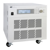
IKONIX apt 460XAC Operation Manual (149 pages)
Modular AC Power Source
Brand:
IKONIX
| Category:
AC Power Distribution
| Size: 5.72 MB
Table of Contents
Table of Contents
3
Introduction
7
Warranty
7
Glossary of Terms
8
Safety Symbols
10
Safety Precautions
10
Service and Maintenance
11
Getting Started
12
Unpacking and Inspection
12
Input/Output Power Considerations
12
Instrument Power Switch
14
Selecting the Appropriate Wire Gauge
14
Power Cable
15
Supplied Input Accessories (460XAC)
19
Environmental Conditions
19
Packaging
20
Specifications and Controls
21
Specifications
21
Measurement Considerations
33
Instrument Controls
35
Front Panel Controls
35
Rear Panel Controls
37
Soft Keys
38
Programming Instructions
40
Powering on the Instrument
40
Set Screen Description
41
Security
42
Lock
43
Mem Lock
43
System Parameters Description
44
Editing System Parameters
46
Editing Auto Run Mode
47
Editing out Mode
48
Editing Single Step (PROGRAM Mode Only)
49
Editing Alarm
49
Editing Contrast
50
Editing Power up
50
Editing Loop Cycle (PROGRAM Mode Only)
51
Editing V Hi-Lmt & V Lo-Lmt (MANUAL Mode Only)
52
Editing F Hi-Lmt & F Lo-Lmt (MANUAL Mode Only)
53
Editing Start and End Angle (MANUAL Mode Only)
54
Editing Results
54
Editing Transient (MANUAL Mode Only)
55
Editing OC Fold
56
Editing Lock
56
Editing Mem Lock
57
Editing Volt Sense
58
Editing Ext Trig
58
Editing Function
59
Smartconfig
59
Using Memories and Steps (PROGRAM Mode Only)
61
Selecting a Memory
61
Naming a Memory
63
Selecting a Step
64
Test Parameters Description
64
Editing Test Parameters
68
Editing Start and End Angle (PROGRAM Mode Only)
70
Editing the Memory Cycle (PROGRAM Mode Only)
71
Editing the Memory (PROGRAM Mode Only)
72
Editing the Step (PROGRAM Mode Only)
72
Editing Voltage
73
Editing Frequency
74
Editing Transient * (PROGRAM Mode Only)
74
Editing Trans-Volt* (PROGRAM Mode Only)
75
Editing Trans-Site* (PROGRAM Mode Only)
76
Editing Trans-Time* (PROGRAM Mode Only)
77
Editing Trans-Cycle* (PROGRAM Mode Only)
77
Editing Ramp up (PROGRAM Mode Only)
79
Editing Timer Unit (PROGRAM Mode Only)
80
Editing Delay (PROGRAM Mode Only)
80
Editing Dwell (PROGRAM Mode Only)
81
Editing Ramp down (PROGRAM Mode Only)
82
Editing Step Cycle (PROGRAM Mode Only)
82
Editing a Hi-Lmt & a Lo-Lmt (PROGRAM Mode Only)
83
Editing P Hi-Lmt & P Lo-Lmt (PROGRAM Mode Only)
84
Editing Ap Hi-Lmt & Ap Lo-Lmt (PROGRAM Mode Only)
85
Editing CF Hi-Lmt & CF Lo-Lmt (PROGRAM Mode Only)
86
Editing PF Hi-Lmt & PF Lo-Lmt (PROGRAM Mode Only)
87
Editing VA Hi-Lmt & VA Lo-Lmt (PROGRAM Mode Only)
88
Editing Q Hi-Lmt & Q Lo-Lmt (PROGRAM Mode Only)
89
Editing Prompt
90
Editing Connect
91
Editing Phase Set
92
Reviewing Test Results
92
Test Modes
94
Description of Test Modes
94
Initializing a Test in PROGRAM Mode
94
AC Output
94
DC Output
96
Initializing a Test in MANUAL Mode
97
AC Output
97
DC Output
98
Displayed Messages
100
OTP - over Temperature Protection
100
OCP - over Current Protection
100
OPP - over Power Protection
100
OVP - Output Voltage Protection
101
A-SH - Amplifier Shutdown Protection
101
RCP - Reverse Current Protection
101
LVP - Low Voltage Protection
101
Displayed if the Power Source Detects a Discrepancy between the Output Voltage Setting of 10V or Greater for more than 1 Sec. the LED Indicator the Test/Reset Key will be Blinking
101
Remote PLC
102
Signal Output
102
Signal Input and Remote Interlock
102
Bus Remote Interface USB/GPIB/RS-232
105
USB/RS-232 Interface
105
Connector
106
Communication Port Configuration
106
Sending and Receiving Commands
106
GPIB Interface
107
GPIB Connector
107
GPIB Address
107
Interface Functions
107
USB/GPIB/RS-232 Interface Command List
108
Basic Commands and Query Commands
108
3Φ4W Queries
113
1Φ3W Queries
115
Program Commands and Companion Queries
116
System Commands and Companion Queries
119
IEEE 488.2 Common Commands
120
Calibration Procedure
124
Hardware Verification and Calibration Procedure
124
Required Measurement Standard
124
Required Measurement Equipment
124
Activate Non-Calibration Mode
124
Adjust the Power Voltage for Control Circuit
124
Adjust the Amplifier Inverter DC Bus Voltage
125
Clear the Output High Frequency Ripple and Noise
125
Adjust the Output "0" Volts and "110" Volts DC Offset
125
Software Calibration Procedure
127
Enter Calibration Mode
128
Calibration of Voltage 150.0V
128
Calibration of Voltage 300.0V
129
Calibration of High and Low Current Range
130
Calibration of Peak Current
131
Options
132
Opt. 03 - GPIB Card
132
Opt. 06 - Ethernet Card
132
Ethernet Card Setup
133
Saving New Settings
135
Power up
135
Ethernet Card Menu
137
IP Setup
137
IP Address
138
Gateway IP
138
Subnet Mask
138
Device Name
139
MAC Address
140
Barcode Input
140
Autostart
142
Ethernet Card Settings Commands and Companion Queries
144
Ethernet Card Settings Command Wait Times
145
Service and Maintenance
146
Replacement Parts List
147
Advertisement
Advertisement
Related Products
IKONIX apt 400XAC Series
IKONIX apt 430XAC
IKONIX Associated Research Hypot III
IKONIX Associated Research HYAMP III
IKONIX EEC 6700 Series
IKONIX Categories
Test Equipment
Switch
AC Power Distribution
Measuring Instruments
Lighting Equipment
More IKONIX Manuals
Login
Sign In
OR
Sign in with Facebook
Sign in with Google
Upload manual
Upload from disk
Upload from URL