
Related Manuals for IKONIX apt 400XAC Series

Summary of Contents for IKONIX apt 400XAC Series
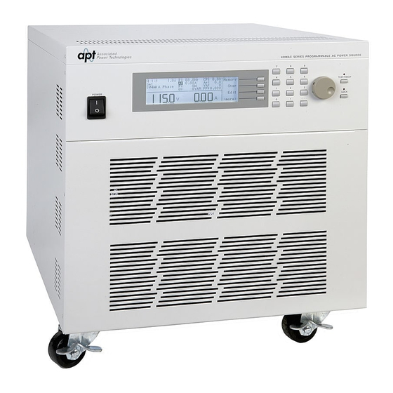
- Page 1 400XAC Series Modular AC Power Source Operation Manual for Models 430XAC 460XAC PART # 39469 Ver. 1.12 January 04th, 2021...
- Page 2 DECLARATION OF CONFORMITY Manufacturer: Associated Power Technologies, Inc. Address: 28105 N Keith Drive Lake Forest, IL 60045 Product Name: 400XAC Power Source Model Number: 430XAC & 460XAC Conforms to the following Standards: Safety: EN 61010-1:2010 EMC: EN 61326-1:2013 Class A, IEC 61000-3-3:2008, IEC 61000-3-11:2000, IEC 61000-3-12:2011, EN 61326-1:2013, IEC 61000-4-2:2008, IEC 61000-4- 3:2006+A1:2007+A2:2010, IEC 61000-4-4:2004+A1:2010, IEC 61000-4- 5:2005, IEC 61000-4-6:2008, IEC 61000-4-8:2009, IEC 61000-4-11:2004,...
-
Page 3: Table Of Contents
Table of Contents Introduction ....................1 Warranty ....................1 Glossary of Terms ................... 2 1.1. Safety Symbols ..................4 Safety Precautions ................. 4 Service and Maintenance ............... 5 Getting Started ....................6 Unpacking and Inspection ..............6 Input/Output Power Considerations ............6 Instrument Power Switch ................ - Page 4 4.3.13 Editing OC Fold ................50 4.3.14 Editing Lock ................... 50 4.3.15 Editing Mem Lock ................51 4.3.16 Editing Volt Sense ................. 52 4.3.17 Editing Ext Trig ................52 4.3.18 Editing Function ................53 SmartConfig .................. 53 Using Memories and Steps (PROGRAM Mode only) ......55 4.4.1 Selecting a Memory ...............
- Page 5 Initializing a Test in MANUAL Mode ............91 5.3.1 AC Output ..................91 5.3.2 DC Output ..................92 Displayed Messages ..................94 OTP – Over Temperature Protection ............ 94 OCP – Over Current Protection ............94 OPP – Over Power Protection .............. 94 OVP –...
- Page 6 9.11 Calibration of High and Low Current Range ........124 9.12 Calibration of Peak Current ..............125 10. Options ....................... 126 10.1 Opt. 03 – GPIB Card ................126 10.2 Opt. 06 – Ethernet Card..............126 10.3 Ethernet Card Setup ................127 10.3.1 Saving New Settings ..............
-
Page 7: Introduction
Introduction Warranty Ikonix USA, certifies that the power source listed in this manual meets or exceeds published manufacturing specifications. This power source was calibrated using standards that are traceable to the National Institute of Standards and Technology (NIST). Your new power source is warranted to be free from defects in workmanship and material for a period of (5) years from date of shipment. -
Page 8: Glossary Of Terms
Glossary of Terms Alternating Current (AC) - current that reverses direction on a regular basis (usually 60 times per second in the United States). Measured in amps. AC Power Source - An instrument that takes one AC voltage and frequency level and converts it into another AC voltage and frequency level. - Page 9 PFC - Power Factor Correction is a method by which an inductance is inserted into the input circuit of a power source to improve the power factor and overall efficiency of the system. Phase Angle - the degree of measurement that corresponds to an AC waveform’s amplitude.
-
Page 10: Safety Symbols
Total Harmonic Distortion (THD) - A percentage that is used to identify the degree of the noise/unclean signal in a power source’s output waveform. Transient - a momentary change (spike or dip) in a voltage or current waveform that can affect the performance of the DUT. Verification - comparison of measured results against a specification, usually the manufacturer's published performance figures for the product (e.g. -
Page 11: Service And Maintenance
• Before applying power verify that the instrument is set to the correct line voltage and the correct fuse is installed To prevent accidental injury or death, these safety procedures must be strictly observed when handling and using the test instrument. Service and Maintenance User Service To prevent electric shock do not remove the instrument cover. -
Page 12: Getting Started
Getting Started This section contains information for the unpacking, inspection, preparation for use and storage of your APT product. Unpacking and Inspection Your instrument was shipped in a protective shipping carton designed to protect the instrument through the shipping process. If the shipping carton is damaged, inspect the contents for visible damage such as dents, scratches, or broken display. - Page 13 430XAC 4500 4000 3500 Input/VA 3000 2500 2000 1500 1000 1000 1500 2000 2500 3000 3500 Output/VA 460 XAC 9000 8000 7000 6000 Input/VA 5000 4000 3000 2000 1000 1000 2000 3000 4000 5000 6000 7000 Output/VA...
-
Page 14: Instrument Power Switch
Instrument Power Switch The power switch that is included in the instrument is not considered a disconnecting device. It only disconnects one current carrying conductor to power off the device. The user should configure the equipment with an external switch or circuit breaker for disconnecting it from each operating energy supply source. -
Page 15: Power Cable
Power Cable Before connecting power to this instrument, the protective ground (earth) terminals of this instrument must be connected to the protective conductor of the line (mains) power cord. The main plug shall only be inserted in a socket outlet (receptacle) provided with a protective ground (earth) contact. - Page 16 Power System Rear Panel 360XAC 460XAC PFC1 AC IN 1P2W 1P2W PFC2 AC IN 3P3W 3P3W PFC3 AC IN 3P4W 3P4W 400XAC Output Power Considerations Figure 1: Input/Output Terminal Block and Output Connection Description...
- Page 17 Figure 2: 3Ø4W Configuration (Wye Load) Figure 3: 3Ø3W Configuration (Delta Load)
- Page 18 Figure 4: 1Ø2W Configuration Figure 5: 1Ø3W Configuration...
-
Page 19: Supplied Input Accessories (460Xac)
Figure 6: DC Output Configuration Supplied Input Accessories (460XAC) Accessory: 1P2W 3P3W 3P4W Shorting Bar 39177 Shorting Bar 39178 Shorting Bar 39179 Screw 39243 Environmental Conditions Operating Environment Temperatures: 5º - 40º C (41º - 104º F) Relative humidity: 20% - 80% Altitude: 2,000 meters (6,562 feet) Do not block any ventilation openings to prevent over heating of the equipment. -
Page 20: Packaging
components. The instrument should also be protected against temperature extremes which may cause condensation within the instrument. If the instrument is used in a matter not specified by the manufacturer, the protection provided by the instrument may be impaired. Storage and Shipping Environment This instrument may be stored or shipped in environments with the following limits: Temperature………………..-40º... -
Page 21: Specifications And Controls
Specifications and Controls Specifications INPUT 430XAC 460XAC Phase 1Ø 1Ø or 3Ø 1Ø : 200~240 Vac ± 10% Voltage 200~240 Vac ± 10% 3Ø3W : 200~240 Vac ± 10% 3Ø4W : 346~416 Vac ± 10% Frequency 47 - 63 Hz AC OUTPUT 1Ø2W 3000VA... - Page 22 ≦±5mV DC offset Range 5~300 VAC (phase), 8.6~520 VAC (line), 150/300V Auto Range Voltage(*3) Resolution 0.1V Accuracy ±(0.2% of setting + 3counts) Range 40~1000Hz Full Range Adjust Frequency Resolution 0.1Hz at 40.0~99.9Hz , 1Hz at 100~1000Hz Accuracy ±0.03% of setting 0~359∘...
- Page 23 Resolution 0.1V Accuracy ± (0.2% of reading + 3counts) 0.005A~1.200A 0.005A~2.400A Range 1.00A~13.00A 2.00A~26.00A 0.001A Resolution 0.01A ± (1% of reading +5counts) at 40.0- ± (1% of reading +5counts) at 40.0-500Hz 500Hz ± (1% of reading +5counts) at 501-1000Hz and ±...
- Page 24 Calculated V×A Formula 0.0VAR~±120.0VAR 0.0VAR~±240.0VAR Range (*15) 0VAR~±1300VAR 0VAR~±2600VAR Power Reactive 0.1VAR Resolution (Q) (*13) 1VAR Calculated (*14) Formula Range 0 - 10.00 Resolution 0.01 Crest Factor Calculated Ap / A Formula Poly-phase mode(3Ø4W) for Σ measurement Range 0.0-1000.0Hz Frequency Resolution 0.1Hz Accuracy...
- Page 25 0.0VA~360.0VA 0.0VA~720.0VA Range (*15) 300VA~3900VA 600VA~7800VA 0.1VA Power Apparent Resolution (VA) Calculated Formula 0.0VAR~360.0VAR 0.0VAR~720.0VAR Range(*15 300VAR~3900VAR 600VAR~7800VAR 0.1VAR Power Reactive Resolution 1VAR Calculated A VAR + B VAR + C VAR Formula Range Resolution Crest Factor Accuracy Single-phase mode(1Ø2W) Setting (Option)
- Page 26 Range 0.0~999.9s Ramp-Down Timer (second) Resolution 0.1s (*4) Accuracy ± (0.1% + 0.05 sec) 0.5s~999.9s Range 0.1m~999.9m 0.1h~999.9h Delay Timer (*4) Resolution 0.1(s,m,h) Accuracy ± (0.1% + 0.1 sec) Range 0, 0.5s~999.9h (0=continuous) Dwell Timer (*4) Resolution 0.1(s,m,h) Accuracy ± (0.1% + 0.1 sec) Single-phase mode(1Ø2W) measurement...
- Page 27 Range 0 - 1.000 Resolution 0.001 Power Factor Calculated W / VA Formula Range (*15) 0VA~3900VA 0VA~7800VA Power Apparent Resolution (VA) Calculated V×A Formula Range (*15) 0VAR~±3900VAR 0VAR~±7800VAR Power Reactive Resolution 1VAR (Q) (*13) Calculated (*14) Formula Range 0 - 10.00 Resolution 0.01 Crest Factor...
- Page 28 (*4) Accuracy ± (0.1% + 0.05 sec) 1s~999.9s Range 0.1m~999.9m 0.1h~999.9h Delay Timer (*4) Resolution 0.1(s,m,h) Accuracy ± (0.1% + 0.1 sec) Range 0, 1s~999.9h (0=continuous) Dwell Timer (*4) Resolution 0.1(s,m,h) Accuracy ± (0.1% + 0.1 sec) Poly-phase mode(1Ø3W) for per-phase measurement (Option)
- Page 29 ± (1% of reading + 5counts) at 40.0-70.0Hz Accuracy ± (1.5% of reading + 10counts) at 70.1 - 500Hz ± (1.5% of reading + 10counts) at 501 - 1000Hz and CF<1.5 0.0W~120.0W 0.0W~240.0W Range 100W~1300W 200W~2600W 0.1W Resolution Power (*5) ±...
- Page 30 Resolution 0.1V Calculated Formula L1 Voltage + L2 Voltage 0.005A~1.200A 0.005A~2.400A Range (*15) 1.00A~13.00A 2.00~26.00A 0.001A Current(r.m.s) Resolution 0.01A Calculated Formula Range Current(peak) Resolution Accuracy 0.0W~240.0W 0.0W~480.0W Range (*15) 200W~2600W 400W~5200W 0.1W Resolution Power Calculated L1 Power + L2 Power Formula Range 0 - 1.000...
- Page 31 DC OUTPUT (Option) Max. Power 3000W 6000W 0~210V 14.4A 28.8A Max. Current 0~420V 7.2A 14.4A Range : 5-210V <700mV Ripple and Noise (RMS) Range : 5-420V <1100mV Ripple and Noise (p-p) <4.0Vp-p SETTINGS(*6) (Option) Range 5-210V / 5-420V Selectable Voltage(*3) Resolution 0.1V Accuracy...
- Page 32 Resolution 0.1V Accuracy ±(0.2% of setting + 3counts) 0.05A~19.50A 0.05A~39.00A Range Current 0.01A Resolution ± (1% of reading +5counts) Accuracy 0W~3900W 0W~7800W Range Power Resolution ± (2% of reading +5counts) Accuracy Protection Software OCP Over Current 110% of full rated current >1 second Output Short Shut Down Speed (*7) <1 second When over Power 105 ~ 110% of full power >5 second.
-
Page 33: Measurement Considerations
Alarm Volume Setting Range: 0-9 ;0=OFF, 1 is softest volume, 9 is loudest volume. Graphic Display 240 x 64 dot resolution Monographic LCD /Contrast 9 Levels 1-9 PF ≥ 0.97 at Full load ≥78% (at Full load) Efficiency Auto loop cycle 0=Continuous, OFF, 2~9999 On/Off , Setting On when output current over setting Hi-A value it will fold back output Over Current Fold Back... - Page 34 Crest Factor vs Output Voltage % Output Voltage % 2. No load to Full load, for output frequencies of <100Hz reference the Load Regulation (Hardware). For output frequencies>100Hz reference the Load Regulation (Software). Output will stabilize to ±0.5V, <1s. 3. No load 4.
-
Page 35: Instrument Controls
Instrument Controls 3.2.1 Front Panel Controls 1. Power Switch: Rocker style power switch with international ON ( | ) and OFF (0). Please refer to pg. 10 for proper installation of a disconnecting device. 2. Graphic LCD: 240 x 64 Monographic LCD. 3. - Page 36 8. Lock LED: When lit indicates the instrument front panel is locked. 9. Test/Reset Key: Used to turn ON/OFF output voltage, or used to reset the instrument in the event of a failure condition. 10. Test/Reset LED: When lit indicates output is active, or when blinking indicates the instrument is in a failure condition.
-
Page 37: Rear Panel Controls
3.2.2 Rear Panel Controls 1. Remote Output Connector: Provides output to monitor PASS, FAIL, Test-In-Process via relay contact closures. 2. Ext Trigger Connector: Provides the capability to monitor a 5 VDC output signal. 3. Automated Interface Card: Interface card used to control, program, and capture data. -
Page 38: Soft Keys
6. Output Terminal Power Block: provides output power to the DUT. 6a. Phase A for 3Ø4W output mode 6b. Phase B for 3Ø4W output mode 6c. Phase C for 3Ø4W output mode 6d. Neutral terminal 3.2.3 Soft Keys The soft keys enable the operator to navigate through the instrument, change the meter display, name files, and change parameters. - Page 39 settings/readings Edit Allows you to enter a parameter screen to change a parameter Allows you to scroll through the list sequentially Prev Allows you to scroll to the previous parameter setting Next Allows you to scroll to the next parameter setting Change Allows you to open up the parameter for changing Result...
-
Page 40: Programming Instructions
Programming Instructions Powering on the Instrument Turn on the Power switch located on the lower left-hand corner of the front panel. The Initialization screen will appear. After a few seconds the Initialization screen will change to the Set screen. The Set screen will be displayed as follows when in PROGRAM Mode: If you press the <more>... -
Page 41: Set Screen Description
If you press the <more> soft key within the Set screen, the soft keys will change to Result, System, and <top> in the MANUAL Mode. 4.1.1 Set Screen Description When the instrument is in the Set screen the parameters indicate their current settings. -
Page 42: Security
1Φ3W: L1-N Indicates the instrument is set up in 1Φ3W mode as L1-N 1Φ3W: L2-N Indicates the instrument is set up in 1Φ3W mode as L2-N 3Φ4W: A Phase Indicates the instrument is set up in 3Φ4W mode as Phase A 3Φ4W: B Phase Indicates the instrument is set up in 3Φ4W mode as Phase B... -
Page 43: Lock
Forgotten Password If you have forgotten your password, a new password should be entered or enter “0” to disable the password. The old password cannot be recovered. Secure Lock and Mem Lock Access If a password has been created, when you press the Lock or Mem Lock soft key or the key lockout on the front panel, a password pop-up screen will appear. -
Page 44: System Parameters Description
memory and step editing capabilities. Selecting the Mem Lock ON will allow the user to only run the currently loaded memory. System Parameters Description The system parameters change the overall operation of the AC power source. If the operator elects to edit the system parameters this will apply a universal change to every memory and step location for the AC power source when in the Test Parameters menu. - Page 45 5. Contrast - controls the contrast of the display. The setting is from 1 – 9 with 9 being the darkest contrast. 6. Power Up - controls how the output will react once the power switch is toggled on. There are three selections (OFF, ON, LAST). When the parameter is in the OFF state the operator must initialize a test by pressing the Test/Reset key on power up.
-
Page 46: Editing System Parameters
14. Results - changes how the data will be displayed on the LCD graphic display after a test is completed. There are three selections available (LAST, ALL, P/F). The LAST setting displays the last step within the program sequence. The ALL setting will display the results of every step within the test sequence in a list format. -
Page 47: Editing Auto Run Mode
When the System soft key is pressed the system parameter screen will open and show all the parameters available for editing. The screen will look as follows: If the system parameters are set to MANUAL Mode, the screen will look as follows: Use the , ... -
Page 48: Editing Out Mode
Auto Run = indicates the status of the run mode that is programmed into the instrument. Auto Run Mode: indicates the run mode that can be programmed into the instrument. Press the Change soft key to toggle the Auto Run Mode to PROGRAM/MANUAL. To save the parameter, press the Enter soft key. -
Page 49: Editing Single Step (Program Mode Only)
4.3.3 Editing Single Step (PROGRAM Mode only) Use the , soft keys to navigate to the Single Step parameter. Pressing the Edit soft key will provide the following screen: Single Step = indicates the status of the single step mode that is programmed into the instrument. -
Page 50: Editing Contrast
Esc soft key. To move to the next system parameter for editing, press the Next or Prev soft key. The Exit soft key is also available to return to the System parameter screen. When the Enter soft key is pressed the Alarm volume is accepted and you transition into the next system parameter: Contrast. -
Page 51: Editing Loop Cycle (Program Mode Only)
Power UP = indicates the power up mode that is programmed into the instrument. Power UP Mode: indicates the power up mode that can be programmed into the instrument. The power up modes available are ON, OFF or LAST. In the ON mode output will be supplied on power up of the instrument. -
Page 52: Editing V Hi-Lmt & V Lo-Lmt (Manual Mode Only)
4.3.8 Editing V Hi-Lmt & V Lo-Lmt (MANUAL Mode only) Use the , soft keys to navigate to the V Hi-Lmt or V Lo-Lmt parameter. Pressing the Edit soft key will provide one of the following screens: V Hi-Lmt = indicates the voltage high limit that is programmed into the instrument. Voltage High Limit Range: indicates the voltage range that can be programmed into the instrument. -
Page 53: Editing F Hi-Lmt & F Lo-Lmt (Manual Mode Only)
4.3.9 Editing F Hi-Lmt & F Lo-Lmt (MANUAL Mode only) Use the , soft keys to navigate to the F Hi-Lmt or F Lo-Lmt parameter (only selectable for AC output). Pressing the Edit soft key will provide one of the following screens: F Hi-Lmt = indicates the frequency high limit that is programmed into the instrument. -
Page 54: Editing Start And End Angle (Manual Mode Only)
4.3.10 Editing Start and End Angle (MANUAL Mode only) Use the , soft keys to navigate to the Start Angle or End Angle parameter (only selectable for AC output). Pressing the Edit soft key will provide one of the following screens: Start Angle = indicates the start angle that is programmed into the instrument. -
Page 55: Editing Transient (Manual Mode Only)
soft key will provide the following screen: Results = indicates the results mode that is programmed into the instrument. Results Mode: indicates the results mode that can be programmed into the instrument. The Results Modes available are ALL, P/F, or LAST. The ALL mode will show all the testing results after the test is completed. -
Page 56: Editing Oc Fold
The Transient Modes available are ON and OFF. Press the Change soft key to toggle the mode to ON or OFF. To save the parameter, press the Enter soft key. To cancel the editing of the Transient Mode press the Esc soft key. When the Enter soft key is pressed the Transient Mode is accepted and you transition into the next system parameter: Lock. -
Page 57: Editing Mem Lock
Lock = indicates the security lock that is programmed into the instrument. Lock Mode: indicates the lock mode that can be programmed into the instrument. The Lock Modes available are ON and OFF. Press the Change soft key to toggle the mode to ON or OFF. -
Page 58: Editing Volt Sense
is pressed the Mem Lock Mode is accepted and you transition into the next system parameter: Volt Sense. If you wish to bypass editing this parameter and move to the next parameter you can press the Prev or Next soft key. 4.3.16 Editing Volt Sense Use the , ... -
Page 59: Editing Function
Ext trig = indicates the Ext Trig that is programmed into the instrument. Ext Trig Mode: indicates the Ext Trig mode that can be programmed into the instrument. The Ext Trig Modes available are OFF, Start, END, and BOTH. Press the Change soft key to toggle the mode. - Page 60 From the main menu press <more>, then SYSTEM, select Function and press Edit. This will allow the user to select: 1Ø2W, 3Ø4W or 1Ø3W. To switch to DC mode, from the main menu select <more>, then SYSTEM, select Mode and press Edit. This will allow the user to select AC or DC.
-
Page 61: Using Memories And Steps (Program Mode Only)
Using Memories and Steps (PROGRAM Mode only) 4.4.1 Selecting a Memory When in the Set screen use the soft keys <more> or <top> to navigate so the first soft key shows Memory. Now press the Memory soft key and you will see the following screen: Memory = will show you the current memory that is active. - Page 62 2. Press the List soft key to bring up a list of all programmed memories of the instrument. In order to get to the List soft key you will have to press the <more> soft key one time. The display will look as follows: Next you will press the List soft key to provide a list of memories programmed into the instrument.
-
Page 63: Naming A Memory
Now press the Load soft key, which will load the memory and bring you back to the set screen with the current memory and its parameters. If you press the Exit soft key you will be brought back to memory screen, and if you press the Exit soft key again you will go back to the Set screen. -
Page 64: Selecting A Step
To save the memory under the current name you selected via the character map/numeric keypad press the Enter soft key. Pressing the Esc soft key versus the Enter soft key will bring you back to the main memory screen. The screen is as follows: 4.4.3 Selecting a Step To select a step press the Step soft key and the steps will sequence through. - Page 65 4. Memory - gives the operator the flexibility to change and edit the memory location (1-50). 5. Step (PROGRAM Mode only) - gives the operator the flexibility to change and edit the step location (1 – 9). 6. Voltage - gives the operator the flexibility to edit the voltage output. 7.
- Page 66 15. A Hi-Lmt (PROGRAM Mode) - gives the operator the flexibility to program a maximum current threshold or ceiling level. When this level is reached a failure will occur. 16. A Lo-Lmt (PROGRAM Mode only) - gives the operator the flexibility to program a minimum current threshold or floor level.
- Page 67 24. PF Lo-Lmt (PROGRAM Mode only) - gives the operator the flexibility to program a minimum power factor threshold or floor level. If a minimum power factor level is not reached a failure will occur. This insures a load is attached to the power source and there is a minimum power factor present.
-
Page 68: Editing Test Parameters
32. Trans-Cycle - gives the operator the flexibility to program whether the transient voltage will occur continuously for each size wave of the test routine. The operator has the choice of selecting 0 or 1-9999. Trans-Cycle is only selectable when the source is configured for AC output. 33. - Page 69 Use the , soft keys to navigate to the testing parameter that will be changed. When you press the Edit soft key you will be moved to the specific parameter screen for editing. If you press the Exit soft key you will be brought back to the set screen.
-
Page 70: Editing Start And End Angle (Program Mode Only)
When you press the Edit soft key you will be moved to the specific parameter screen for editing. If you press the Exit soft key you will be brought back to the set screen. 4.6.1 Editing Start and End Angle (PROGRAM Mode only) Use the , ... -
Page 71: Editing The Memory Cycle (Program Mode Only)
will apply to the first step in the sequence and the end angle will apply to the last step in the sequence. For example, memory 1 step 7 is linked to memory 1 step 8, memory 1 step 9 and memory 2 step 1 to create a four step sequence of tests. If the start angle is set to 90 degrees and the end angle is set to 180 degrees, the output voltage waveform at memory 1 step 7 will have a start angle at 90 degrees and the output voltage waveform at memory 2 step 1 will end at a 180... -
Page 72: Editing The Memory (Program Mode Only)
pressed and the Memory Cycle is accepted, you transition into the next parameter: Memory. If you wish to bypass editing this parameter and move to the next parameter you can press the Prev or Next soft key. 4.6.3 Editing the Memory (PROGRAM Mode only) Use the , ... -
Page 73: Editing Voltage
The Step parameter can also be edited from the set screen. If you hit the Step soft key, you can use the Step + and Step – soft keys to increase or decrease the step number. When the Enter soft key is pressed and the Step is accepted you transition into the next parameter: Voltage. -
Page 74: Editing Frequency
To change the Voltage mode from Auto to High press the Change soft key to toggle between the two selections. To accept the selection, press the Enter soft key. To cancel the selection, press the Esc soft key. You must press the Enter soft key to accept the range. -
Page 75: Editing Trans-Volt* (Program Mode Only)
Transient = indicates the Transient mode that is programmed into the instrument. Transient Mode: indicates the Transient mode that can be programmed into the instrument. The Transient modes available are ON and OFF. Press the Change soft key to toggle the mode to ON or OFF. To save the parameter, press the Enter soft key. To cancel the editing of the Transient mode press, the Esc soft key. -
Page 76: Editing Trans-Site* (Program Mode Only)
To change the Transient voltage, use the numeric keypad and type the voltage. Once you type in a number a shaded black box (■) will begin blinking acknowledging the parameter is being changed. Press the Enter soft key to accept the voltage, or press the Esc soft key to move back to the Trans-Volt parameter screen. -
Page 77: Editing Trans-Time* (Program Mode Only)
4.6.10 Editing Trans-Time* (PROGRAM Mode only) Use the , soft keys to navigate to the Trans-Time parameter (only selectable for AC output). Pressing the Edit soft key will provide the following screen: Trans-Time = indicates the Transient time that is programmed into the instrument. Transient Pulse Width Range: indicates the Transient pulse width range that can be programmed into the instrument. - Page 78 instrument. Transient Trig Mode: indicates the Transient trigger mode that can be programmed into the instrument. If the Transient Trig mode is ON the transient parameters previously programmed will trigger automatically once the test starts. This will continue to be active until the Trig.
-
Page 79: Editing Ramp Up (Program Mode Only)
When the Trig. soft key is hit one time while the Trans-Cycle is set to OFF, the waveform will look like this: When the Enter soft key is pressed the time is accepted and you transition into the next parameter: Prompt If you wish to bypass editing this parameter and move to the next parameter you can press the Prev or Next soft key. -
Page 80: Editing Timer Unit (Program Mode Only)
To change the ramp up time, use the numeric keypad and type the time. Once you type in a number a shaded black box (■) will begin blinking acknowledging the parameter is being changed. Press the Enter soft key to accept the time, or press the Esc key to move back to the Ramp Up Time Parameter screen. -
Page 81: Editing Dwell (Program Mode Only)
Delay = indicates the delay time that is programmed into the instrument. Delay Time Range: indicates the delay time range that can be programmed into the instrument. To change the delay time, use the numeric keypad and type the time. Once you type in a number a shaded black box (■) will begin blinking acknowledging the parameter is being changed. -
Page 82: Editing Ramp Down (Program Mode Only)
press the Esc soft key to move back to the Dwell Time Parameter screen. When the Enter soft key is pressed, the time is accepted and you transition into the next parameter: Ramp Down. If you wish to bypass editing this parameter and move to the next parameter you can press the Prev or Next soft key. -
Page 83: Editing A Hi-Lmt & A Lo-Lmt (Program Mode Only)
Step Cycle = indicates the step cycle that is programmed into the instrument. Step Cycle Range: indicates the step cycle range that can be programmed into the instrument. The ranges available are 0 – 9999, 0=Cont., 1=Off. The 0 – 9999 selection programs the instrument to repeat the test step cycle x number of times. -
Page 84: Editing P Hi-Lmt & P Lo-Lmt (Program Mode Only)
A Lo-Lmt = indicates the current low limit that is programmed into the instrument. Current Low Limit Range: indicates the current range that can be programmed into the instrument. The A Lo-Lmt parameter setting is only available in the PROGRAM Mode. To change the current high limit or low limit, use the numeric keypad and type the current value. -
Page 85: Editing Ap Hi-Lmt & Ap Lo-Lmt (Program Mode Only)
P Lo-Lmt = indicates the power low limit that is programmed into the instrument. Power Low Limit Range: indicates the power range that can be programmed into the instrument. To change the Power High Limit or Low Limit, use the numeric keypad and type the power value. -
Page 86: Editing Cf Hi-Lmt & Cf Lo-Lmt (Program Mode Only)
Ap Lo-Lmt = indicates the peak current low limit that is programmed into the instrument. Peak Current Low Limit Range: indicates the peak current range that can be programmed into the instrument. To change the Peak Current High Limit or Low Limit use the numeric keypad and type the peak current value. -
Page 87: Editing Pf Hi-Lmt & Pf Lo-Lmt (Program Mode Only)
CF Lo-Lmt = indicates the crest factor low limit that is programmed into the instrument. Crest Factor Low Limit Range: indicates the crest factor range that can be programmed into the instrument. To change the Crest Factor High Limit or Low Limit use the numeric keypad and type the peak current value. -
Page 88: Editing Va Hi-Lmt & Va Lo-Lmt (Program Mode Only)
factor range is turned OFF. PF Lo-Lmt = indicates the power factor low limit that is programmed into the instrument. Power Factor Low Limit Range: indicates the power factor range that can be programmed into the instrument. To change the Power Factor High Limit or Low Limit use the numeric keypad and type the power factor value. -
Page 89: Editing Q Hi-Lmt & Q Lo-Lmt (Program Mode Only)
programmed into the instrument. If you select the 0=OFF apparent power range is turned OFF. VA Lo-Lmt = indicates the apparent power low limit that is programmed into the instrument. VA Low Limit Range: indicates the apparent power range that can be programmed into the instrument. -
Page 90: Editing Prompt
Reactive Power High Limit Range: indicates the reactive power range that can be programmed into the instrument. If you select the 0=OFF reactive power high limit range is turned OFF. Q Lo-Lmt = indicates the reactive power low limit that is programmed into the instrument. -
Page 91: Editing Connect
accept the character. You can also use the numeric keypad to enter characters. When the numeric keypad is used the number is inserted automatically and the Select soft key is not needed. To delete a character use the Backspace key <- - located on the numeric keypad. -
Page 92: Editing Phase Set
accepted and you transition into the next parameter: Memory Cycle. If you wish to bypass editing this parameter and move to the next parameter you can press the Prev or Next soft key. When the connect mode is ON there will be an underscore _ next to the step number in the set screen. - Page 93 Press the Result soft key to view the results. The screen will look as follows: If you have multiple steps linked together you will have to use the navigation soft keys in order to toggle through each step to review the results. Press the Exit soft key to move back to the set screen.
-
Page 94: Test Modes
Test Modes Description of Test Modes Within the System Parameter settings of Auto Mode you have two selections available (PROGRAM/MANUAL). The PROGRAM Mode will run your testing routine according to the parameters that have been entered within the testing parameters screen when the TEST/RESET key is pressed. - Page 95 If you press the Meter soft key a shaded black box (■) will highlight the meter parameters of F:, A:, P:, Q:, CF:, Ap, VA:, PF:, and the display will read the output on the on the right side of the display. Every time the meter key is pressed it will toggle through the meter parameters.
-
Page 96: Dc Output
5.2.2 DC Output When the AUTO RUN parameter in the System Parameters menu is set to PROGRAM Mode the Set screen will be displayed as follows: To initialize the test press the Test/Reset key and the LED for the key will illuminate. -
Page 97: Initializing A Test In Manual Mode
Initializing a Test in MANUAL Mode 5.3.1 AC Output When the AUTO RUN parameter in the System Parameters is set to the MANUAL Mode the Set screen will be displayed as follows: To initialize the test press the Test/Reset key and the LED for the key will illuminate. -
Page 98: Dc Output
flashing waiting for a voltage value to be entered from the numeric keypad. Once the value has been typed into the instrument you must press the Enter soft key to accept the value. The Esc soft key is available to exit out of this mode and move back to the test screen. - Page 99 parameters. If you press the Keypad soft key the display will show the text Voltage = above the voltage meter on the left hand side of the display. A shaded black box (■) will be flashing waiting for a voltage value to be entered from the numeric keypad. Once the value has been typed into the instrument you must press the Enter soft key to accept the value.
-
Page 100: Displayed Messages
Displayed Messages During any abnormal conditions, there are several error messages that could be indicated in the display. When an abnormal condition occurs the output will disable and the alarm will sound. The Test/Reset LED indicator will also begin flashing. Pressing the Test/Reset key will reset the audible alarm and the abnormal condition will be displayed. -
Page 101: Ovp - Output Voltage Protection
OVP – Output Voltage Protection Displayed if the output voltage has exceeded 5 V of the setting voltage in the 0-150V range, or has exceeded 10 V of the setting voltage in the 0-300V range. The LED indicator for the Test/Reset key will be blinking. If an OVP error occurs on the next power up cycle on the displays will show Volt Err. -
Page 102: Remote Plc
Remote PLC Signal Output The rear panel connector of the 400XAC Series provides output signals to remotely monitor PASS, FAIL, and PROCESSING conditions via a 9-Pin D-type connector. When a terminal becomes active the relay closes thereby allowing the external voltage to operate an external device. The following table provides the conditions of each pin and the relay state. - Page 103 The following table provides the conditions of each pin and the relay state: Condition Pins Relay State TEST Connection between PIN 3 & PIN Momentary contact closure RESET Connection between PIN 2 & PIN Momentary contact closure INTERLOCK Connection between PIN 4 & PIN Normally open contact Memory Input Control...
- Page 104 will be displayed and the test will abort. The hardware and has been configured to provide the interlock connections on pins 4 and 5 of the Remote Interface, Signal Input port. The instrument can still be used without the external interlock device as long as the Interlock Disable Key is plugged into the Remote Interface, Signal Input port.
-
Page 105: Bus Remote Interface Usb/Gpib/Rs-232
Bus Remote Interface USB/GPIB/RS-232 This section provides information on the proper use and configuration of bus remote interface. The USB/RS-232 remote interface is standard on model 400XAC series but the GPIB (IEEE-488) interface option can be substituted for the USB/RS-232 interface. Please refer to the Option section of this manual for details on the 400XAC series options. -
Page 106: Connector
8.1.1 RS-232 Connector The RS-232 connection is configured as follows for a 9 pin Serial Port Interface. RD 2 2 RD TD 3 3 TD SIG 5 5 SIG 8.1.2 Communication Port Configuration The COM port should have the following configuration: •... -
Page 107: Gpib Interface
be terminated with LF=(0AH), such as ”TEST”+LF. GPIB Interface 8.2.1 GPIB Connector Connection is usually accomplished with a 24-conductor cable with a plug on one end and a connector at the other end. Devices may be connected in a linear, star or a combination configuration. -
Page 108: Usb/Gpib/Rs-232 Interface Command List
A GPIB read command must be sent after the command strings, to retrieve any data from a query command (?). The APT 400XAC series GPIB bus will not send any data to the controller without being queried. The USB/RS-232 bus will automatically send any response back to the controller’s input buffer. - Page 109 from the instrument. This command set also includes query commands. These query commands will retrieve data from the instrument. The GPIB bus application requires an IEEE-488 read command to be sent after the query command. These commands include functions for retrieving test data, test results and metering values.
- Page 110 Read the active data being displayed on the LCD display while the test is in process. Will also read the last data taken when the test sequence has completed. Each parameter is separated by commas and includes memory number, step number, test status, frequency value, voltage value, current value, power value, peak current value, power factor value and timer metering.
- Page 111 TDCF? Read the active crest factor value being displayed while a test is in process. TDVA? Read the active apparent power value being displayed while a test is in process. TDTIMER? Read the active timer meter value being displayed while a test is in process. METER {4|3|2|1|0} Selects the metered value that is displayed while a test is in process.
- Page 112 or current. EXTP External trigger pulse. Trigger one pulse with relation to how the SYNC event is set.
-
Page 113: 3Φ4W Queries
8.4.2 3Φ4W Queries The following commands are used to query the instrument while in Polyphase mode. AC Range AC Range Manual DC Range DC Range Manual COMMAND DESCRIPTION Unit Program Mode Mode Program Mode Mode TDA? Testing AØ meter data TDB? Testing BØ... - Page 114 TDC-P? Testing power meter See Note3-1 TDC-PF? Testing pf meter 0.000~1.000 TDC-Q? Testing Q meter See Note3-1 TDC-CF? Testing CF meter 0.00~10.00 TDC-VA? Testing VA meter See Note3-1 TDE-VOLT? Testing voltage meter 0.0~300.0 TDE-CURR? Testing current meter See Note1-1 TDE-P? Testing power meter See Note3-1 TDE-PF?
-
Page 115: 1Φ3W Queries
Query only available in AC Program mode and AC Manual mode. 8.4.3 1Φ3W Queries The following commands are used to query the instrument while in Parallel mode. AC Range AC Range Manual DC Range DC Range Manual COMMAND DESCRIPTION Unit Program Mode Mode Program Mode... -
Page 116: Program Commands And Companion Queries
TDL1L2Q? Testing Q meter See Note3-1 TDL1L2VA? Testing VA meter See Note3-1 TDL1N? Read the selected L1-N meter values while a test is in process. TDL2N? Read the selected L2-N meter values while a test is in process. TDL1L2? Read the selected total (L1-L2) meter values while a test is in process. RDL1N XX? Read the selected L1-N results once a test has completed. - Page 117 VOLT XXX.X VOLTAGE XXX.X XXXX=0.0~300.0 XXXX=5.0~420.0 or 5.0~210.0 VOLT? VOLTAGE? 0.0~300.0 5.0~420.0 or 5.0~210.0 RANG X RANG X X=0-1, 0=HIGH,1=AUTO X=0-1, 0=HIGH,1=LOW RANG? RANG? FREQ XXXX FREQUNCY XXXX XXXX=40.0~1000 FREQ? FREQUNCY? 40.0~1000 SD X TRANSIENT X X=0~1, 0=OFF,1=ON TRANSIENT? TRANSIENT-VOLT SDVOLT XXXX XXXX=0.0~300.0 XXXX...
- Page 118 PHI XXXX POWER HI XXX.X PHI? POWER HI? See Note3 See Note3 PLO XXXX POWER LO XXX.X PLO? POWER LO? APHI XX.X AP HI XX.X APHI? AP HI? See Note4 APLO XX.X AP LO XX.X APLO? AP LO? PFHI XXXX PF HI X.XXX XXXX=0.000~1.000 PFHI?
-
Page 119: System Commands And Companion Queries
8.4.5 System Commands and Companion Queries These commands are used to modify the system parameters for the instrument. These commands require a parameter value to be included with the command. The companion query command will read the parameter using the same value that is used for setting the parameter. -
Page 120: Ieee 488.2 Common Commands
OF X OC Fold X X=0~1, 0=OFF,1=ON OC Fold? SD X TRANSIENT X X=0~1,0=OFF,1=ON TRANSIENT? LOCK X LOCK X X=0~1, 0=OFF,1=ON LOCK? LOCK? MEMLOCK X MEMLOCK X X=0~1, 0=OFF,1=ON MEMLOCK? MEMLOCK? VOLT SENSE VS X X=0~1, 0=INT,1=EXT VOLT SENSE? FUNCTION X FUNCTION X X=0~2, 0=1Ø2W, 1=3Ø4W, 2=1Ø3W FUNCTION? - Page 121 Command Name Description When TEST command ok setting *OPC Operation Complete Command ESR BIT0 =1 0 = Test in Process *OPC? Operation Complete Query 1 = Test Complete OK *WAI Wait for next command Standard Event Status Register BIT 0 ,01H, (1) Operation *ESR? Query...
- Page 122 *RST Reset the instrument to original power on configuration. Does not clear Enable register for Standard Summary Status or Standard Event Registers. Does not clear the output queue. Does not clear the power-on-status-clear flag. *TST? Performs a self test of the instrument data memory. Returns 0 if it is successful or 1 if the test fails.
- Page 123 binary-weighted sum of bits. *PSC {1|0} Sets the power-on status clear bit. When set to 1 the Standard Event Enable register and Status Byte Enable registers will be cleared when power is turned ON. 0 setting indicates the Enable registers will be loaded with Enable register masks from non-volatile memory at power ON.
-
Page 124: Calibration Procedure
Calibration Procedure All Associated Power Technologies, Inc. instruments have been calibrated at the factory prior to delivery. The recommended calibration cycle for all APT instruments is every 12 months. Hardware Verification and Calibration Procedure This instruction sheet covers the hardware calibration procedure for the 400XAC power supply. -
Page 125: Adjust The Amplifier Inverter Dc Bus Voltage
9.4. Adjust the Amplifier Inverter DC Bus Voltage 1. Connect the DVM to the TP6(+) and TP7(-) points on the DDC61000 board and set to DC volts. 2. Power up the instrument. 3. The instrument without load and idling condition. 4. - Page 126 instrument A B C N R475K C 10uF 4. Press the “0” and “7” number key while simultaneously powering the instrument on. 5. Set the output voltage to “0” volts in the low voltage range and activate the output of the instrument. 6.
-
Page 127: Software Calibration Procedure
Software Calibration Procedure The software calibration is recommended to be performed after the hardware verification and hardware calibration has been completed. Required Measurement Standard • 0-40 Amp AC True RMS Ammeter • 0-300 VAC True RMS Voltmeter Required Measurement Equipment 430XAC •... -
Page 128: Enter Calibration Mode
Enter Calibration Mode To enter the calibration mode power on the unit while holding the 4 key on the numeric keypad. When in the calibration mode the display will look as follows: Use the up or down arrow soft keys to navigate to the parameter that you would like to calibrate. -
Page 129: Calibration Of Voltage 300.0V
Enter the voltage reading from the voltmeter with the numeric keypad. When the value has been selected press the Enter soft key and you will be moved to the next calibration parameter Voltage 300.0V. If you press the Esc soft key you will be returned to the calibration mode screen. -
Page 130: Calibration Of High And Low Current Range
Enter the voltage reading from the voltmeter with the numeric keypad. When the value has been selected press the Enter soft key and you will be moved to the next calibration parameter Current xx.xA. If you press the Esc soft key you will be returned to the calibration mode screen. -
Page 131: Calibration Of Peak Current
returned to the calibration mode screen. 9.12 Calibration of Peak Current Use the , soft keys to navigate to the A-Peak xx.xA parameter and press the Select soft key. Follow the prompt message provided on the display, and press the Test/Reset button to move into the calibration screen for current. -
Page 132: Options
10. Options Opt. 03 – GPIB Card 10.1 This option provides the GPIB card in place of the standard USB/RS-232 interface. Opt. 06 – Ethernet Card 10.2 The Ethernet Card option provides RS-232 and Ethernet communication interfaces, as well as barcode scanning capability. The Ethernet Card has three input/output ports, shown in the following figure: The port labeled “Barcode”... -
Page 133: Ethernet Card Setup
IP Address: 010.000.000.000 Gateway IP: 000.000.000.000 Subnet Mask: 255.000.000.000 The source port number for the Ethernet Card in TCP connections is 10001. 10.3 Ethernet Card Setup In order to setup the Ethernet card, the operator will need information from the local network administrator. - Page 134 Associated Power Technologies, Inc. Ethernet Card Communications Information (To be completed by Network Administrator) Ethernet Card Address: ______:______:______:______:______ Device Name: _____________________ Device IP Address: _______._______._______._______ Gateway IP Address: _______._______._______._______ Subnet Mask: _______._______._______._______...
-
Page 135: Saving New Settings
10.3.1 Saving New Settings Upon startup, the Ethernet Card will take a few seconds to initialize. The following message will be displayed: Any time the user edits one of the Ethernet Card parameters and exits the Ethernet Card Settings menu, the following message will be displayed: The Ethernet Card will attempt to re-establish a connection with the server anytime the user modifies a parameter and exits the Ethernet Card Parameters Menu or uses the command set at the end of this option description. - Page 136 Note: The “Requesting IP Address…” pop-up message only appears at power up when the Ethernet Card has its IP Setup configured to AUTO. There are two options to choose from this screen. Press the Exit soft key to escape from this screen and stop the APT 400XAC from requesting an IP address or allow the APT 400XAC to request an IP address automatically from the network to which it is connected.
-
Page 137: Ethernet Card Menu
10.3.4 Ethernet Card Menu When the Ethernet Card option is installed, the ENET soft key will appear in the Perform Tests screen as shown below: To access the Ethernet Card Menu, press the <more> soft key at the Perform Tests screen. Press the ENET soft key to display the Ethernet Card Parameters screen: 10.3.5 IP Setup Highlight the IP Setup parameter using the , ... -
Page 138: Ip Address
10.3.6 IP Address Highlight the IP Address parameter using the , soft keys. When the IP Address parameter is highlighted, press the Edit soft key. A specific IP Address must be entered into this field if the IP Setup parameter is configured to MANUAL. -
Page 139: Device Name
A specific Subnet Mask must be entered into this field if the IP Setup parameter is configured to MANUAL. Enter the Subnet Mask using the numeric keypad. The Subnet Mask must be entered in the following format: XXX.XXX.XXX.XXX. If an invalid Subnet Mask is entered the following error message will be displayed: Press the Enter soft key to save the new settings. -
Page 140: Mac Address
When the Device Name has been entered, press the Enter soft key to save the new settings. The Device Name parameter is only active when the IP Setup is set to AUTO. 10.3.10 MAC Address View the MAC address of the Ethernet Card here. This parameter is not adjustable. - Page 141 After the barcodes are scanned, press Test to initiate the test sequence. Pressing Reset will abort the test sequence. The Ethernet Card permits re-scanning of barcodes if the previously scanned barcode was incorrect. Re-scanning is only available in the SERIAL#, PRODUCT# and SER/PROD modes.
-
Page 142: Autostart
1,1,Pass,60.0,115.2,0.306,24.7,0.9,0.632,20.0,123456789,0 Note that there is a “0” in the Product Number field because the Barcode INPUT setting is SERIAL#. When the Barcode INPUT setting is RUN FILE or OFF, these fields are not included in the TD? and RD x? responses. Use the Change soft key to select the Barcode INPUT. - Page 143 setting.
-
Page 144: Ethernet Card Settings Commands And Companion Queries
10.3.13 Ethernet Card Settings Commands and Companion Queries Command Name Value SIM {1|0} Set IP Mode 1=Manual, 0=Auto SIM? (DHCP/BOOTP) SIA <value> Set IP Address Dotted decimal form. Ex. SIA? 192.168.1.50 SGA <value> Set Gateway IP Dotted decimal form SGA? Address SSM <value>... -
Page 145: Ethernet Card Settings Command Wait Times
10.3.14 Ethernet Card Settings Command Wait Times IP Mode Command Wait Time After Command is Sent* SIA, SGA, SSM 8 seconds Manual SIM 0 14 seconds 14 seconds Auto SIM 1 8 seconds *Wait times are approximate and can vary based on the user’s network. -
Page 146: Service And Maintenance
11. Service and Maintenance User Protection To avoid electrical shock do not dismantle the cover of the instrument. When any abnormal symptom happens with the instrument, please contact Associated Power Technologies, Inc. or the authorized distributor for assistance. Consistency of Service The instrument’s internal circuits and all related parts are required to be checked and calibrated at least once every year. -
Page 147: Replacement Parts List
12. Replacement Parts List Rev:A ECO 5763, 05/27/2015 Part Number Qty. Ref. Description Designator Supplied Accessories 38787 3U Rack Mount Handle 39435 9U Rack Mount Bracket Left 39436 9U Rack Mount Bracket Right 39174 Screw for Rack Mount Handle to Rack Mount Bracket 39066 USB Cable AB Type 1.8m... - Page 148 Part Number Qty. Ref. Description Designator 39444 Right Side Panel 39220 EVR1 Rotary Encoder 38973 Rotary Knob 38274 Button Keypad Rect. 9.8 x 8.0mm 38275 Button Keypad Rect. 9.8 x 4.9mm Front Wheel with brake 3.5” H 39664 Rear Wheel 3.5” H 39665 38916 Graphic LCD Display...
- Page 149 39131 FLY61040 FLY Back Board 39438 OPTAC300 Output Board (430XAC) 39464 OPTAC300 Output Board (460XAC) 39439 PLDM001 PLD Board 39449 PWMAC300 PWM Board Internal Components Part Number Qty. Ref. Description Designator 38338 Fan 24VDC 240mm (460XAC) 38808 Fan 24VDC 60mm (460XAC) 39263 4-(430XAC) Fan 24VDC 120mm...
Need help?
Do you have a question about the apt 400XAC Series and is the answer not in the manual?
Questions and answers