Sign In
Upload
Manuals
Brands
IEI Technology Manuals
Motherboard
tKINO-BW-N2-R10
User Manuals: IEI Technology tKINO-BW-N2-R10 Camera
Manuals and User Guides for IEI Technology tKINO-BW-N2-R10 Camera. We have
1
IEI Technology tKINO-BW-N2-R10 Camera manual available for free PDF download: User Manual
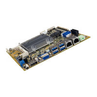
IEI Technology tKINO-BW-N2-R10 User Manual (143 pages)
Brand:
IEI Technology
| Category:
Motherboard
| Size: 3.97 MB
Table of Contents
Table of Contents
5
1 Introduction
15
Figure 1-1: Tkino-BW
16
Table 1-1: Tkino-BW Model Variations
17
Figure 1-2: Connectors
18
Dimensions
19
Figure 1-3: Dimensions (MM)
19
Data Flow
20
Figure 1-4: Data Flow Diagram
20
Technical Specifications
21
Connectors
18
Introduction
16
Features
17
Model Variations
17
Table 1-2: Technical Specifications
23
2 Unpacking
24
Anti-Static Precautions
25
Unpacking Precautions
25
Packing List
26
Optional Items
27
3 Connectors
28
Figure 3-1: Connector and Jumper Locations
29
Peripheral Interface Connectors
29
Tkino-BW Layout
29
Peripheral Interface Connectors
30
External Interface Panel Connectors
31
Table 3-2: Rear Panel Connectors
31
Table 3-3: DC-IN Power Connector Pinouts
32
Battery Connector
33
Table 3-1: Peripheral Interface Connectors
31
Figure 3-2: DC-IN Power Connector Location
32
Internal Peripheral Connectors
32
30 V DC-IN Power Connector
32
Audio Connector
32
Figure 3-3: Audio Connector Location
33
Figure 3-4: Battery Connector Location
34
Figure 3-5: Chassis Intrusion Connector Location
35
Table 3-7: Digital I/O Connector Pinouts
36
Fan Connectors
37
Table 3-4: Audio Connector Pinouts
33
Table 3-6: Chassis Intrusion Connector Pinouts
35
Digital I/O Connector
36
Table 3-5: Battery Connector Pinouts
34
Chassis Intrusion Connector
35
Figure 3-6: Digital I/O Connector Location
36
Figure 3-7: Fan Connector Locations
37
Table 3-8: Fan Connector Pinouts
37
Figure 3-13: LAN LED Connector Locations
43
Figure 3-14: Microsd Card Slot Location
44
Microsd Slot
44
Msata Module Slot
44
LAN LED Connectors
43
Table 3-13: LVDS Connector Pinouts
43
Table 3-14: LAN LED Connector Pinouts
43
Figure 3-15: Msata Module Slot Location
45
Figure 3-16: Pcie Mini Card Slot Location
46
Pcie Mini Card Slot
46
Table 3-15: Msata Module Slot Pinouts
46
Pcie X1 Card Slot
47
Table 3-16: Pcie Mini Card Slot Pinouts
47
Figure 3-17: Pcie X1 Slot Location
48
Table 3-17: Pcie X1 Slot Pinouts
48
Figure 3-27: External Peripheral Interface Connector
58
Figure 3-29: DP/HDMI Connector Pinout Locations
59
Table 3-27: DP/HDMI Connector Pinouts
59
Figure 3-30: LAN Connector
60
LAN Connectors
60
Table 3-28: LAN Pinouts
60
USB Connectors
60
VGA Connector
61
Figure 3-18: RS-232 Serial Port Connector Locations
49
Serial Port Connector
49
Table 3-18: RS-232 Serial Port Connector Pinouts
49
Figure 3-19: RS-232/422/485 Connector Locations
50
RS-232/422/485 Serial Port Connector
50
Table 3-19: RS-232/422/485 Connector Pinouts
50
Figure 3-20: SATA 6Gb/S Drive Connectors Locations
51
SATA 6Gb/S Drive Connectors
51
Table 3-20: DB-9 RS-422/485 Pinouts
51
Figure 3-21: SATA Power Connector Locations
52
SATA Power Connectors
52
Table 3-21: SATA Power Connector Pinouts
52
Figure 3-22: SMBUS Connector Location
53
Smbus Connector
53
Table 3-22: SMBUS Connector Pinouts
53
Figure 3-23: SPI Flash Connector Location
54
SPI Flash Connector, BIOS
54
Table 3-23: SPI Flash Connector Pinouts
54
Figure 3-24: SPI Flash Connector Location
55
SPI Flash Connector, EC
55
Table 3-24: SPI Flash Connector Pinouts
55
Figure 3-25: TPM Connector Location
56
Table 3-25: TPM Connector Pinouts
56
TPM Connector
56
Figure 3-26: USB Connector Location
57
Table 3-26: USB Connector Pinouts
57
USB Connector
57
Audio Line-Out Connector
58
External Peripheral Interface Connector Panel
58
Figure 3-28: Audio Line-Out Connector
58
HDMI Connector
59
Figure 3-8: Front Panel Connector Location
38
Front Panel Connector
38
Table 3-9: Front Panel Connector Pinouts
38
Figure 3-9: I 2 C Connector Location
39
I 2 C Connector
39
Table 3-10: I 2 C Connector Pinouts
39
Figure 3-10: Keyboard and Mouse Connector Location
40
Keyboard and Mouse Connector
40
Table 3-11: Keyboard and Mouse Connector Pinouts
40
Figure 3-11: Backlight Inverter Connector Location
41
LVDS Backlight Inverter Connector
41
Table 3-12: Backlight Inverter Connector Pinouts
41
Figure 3-12: LVDS Connector Location
42
LVDS LCD Connector
42
Table 3-30: VGA Connector Pinouts
61
Figure 3-31: VGA Connector
61
Table 3-29: USB 3.0 Port Pinouts
61
4 Installation
62
Anti-Static Precautions
63
Installation Considerations
63
Figure 4-1: SO-DIMM Installation
65
Figure 4-2: Microsd Card Installation
66
Msata Module Installation
67
Full-Size Msata Module Installation
67
So-DIMM Installation
65
Microsd Card Installation
66
Figure 4-3: Removing the Retention Screw
67
Figure 4-10: Securing the Half-Size Msata Module
71
Figure 4-11: Removing the Retention Screws
71
Figure 4-12: Inserting the Full-Size Pcie Mini Card into the Slot at an Angle
72
Figure 4-13: Securing the Full-Size Pcie Mini Card
72
Figure 4-15: Installing the Standoff
74
Figure 4-16: Inserting the Half-Size Pcie Mini Card into the Slot at an Angle
74
AT/ATX Mode Select Switch
75
Figure 4-17: Securing the Half-Size Pcie Mini Card
75
System Configuration
75
Table 4-1: AT/ATX Mode Select Switch Settings
75
Clear CMOS Button
76
Figure 4-18: AT/ATX Mode Select Switch Location
76
Figure 4-19: Clear CMOS Button Location
76
Figure 4-20: HDMI/DP Select Switch Location
77
HDMI/DP Select Switch
77
Table 4-2: HDMI/DP Select Switch Settings
77
LVDS Panel Resolution Select Switch
78
Table 4-3: LVDS Panel Resolution Selection
78
Figure 4-21: LVDS Panel Resolution Select Switch Location
79
LVDS Voltage Select Jumper
79
Table 4-4: LVDS Voltage Select Jumper Settings
79
Figure 4-22: LVDS Voltage Select Jumper Location
80
Msata and SATA2 Select Jumper
80
Table 4-5: Msata and SATA2 Select Jumper Settings
80
Airflow
81
Chassis Installation
81
Figure 4-23: Msata and SATA2 Select Jumper Location
81
Motherboard Installation
81
Figure 4-24: SATA Drive Cable Connection
82
Sata Drive Connection
82
Figure 4-25: IEI Resource Download Center
83
Software Installation
83
Driver Download
84
Figure 4-4: Inserting the Full-Size Msata Module into the Slot at an Angle
68
Figure 4-5: Securing the Msata Module
68
Figure 4-7: Removing the Standoff
69
Figure 4-6: Removing the Retention Screw
69
Figure 4-8: Installing the Standoff
70
Figure 4-9: Inserting the Half-Size Msata Module into the Slot at an Angle
70
Pcie Mini Card Installation
71
Full-Size Pcie Mini Card Installation
71
Figure 4-14: Removing Retention Screw and Standoff
73
Half-Size Pcie Mini Card Installation
73
Half-Size Msata Module Installation
69
5 Bios
86
Introduction
87
Starting Setup
87
Using Setup
87
Getting Help
88
Unable to Reboot after Configuration Changes
88
BIOS Menu Bar
88
Table 5-1: BIOS Navigation Keys
88
Main
89
Advanced
90
ACPI Settings
91
RTC Wake Settings
92
Trusted Computing
93
CPU Configuration
94
SATA Configuration
95
USB Configuration
96
Nvme Configuration
97
F81866 Super IO Configuration
98
Serial Port N Configuration
98
Serial Port 1 Configuration
99
Serial Port 2 Configuration
100
Serial Port 3 Configuration
101
Serial Port 4 Configuration
102
Serial Port 5 Configuration
103
Serial Port 6 Configuration
104
Iwdd H/W Monitor
105
Smart Fan Mode Configuration
106
Serial Port Console Redirection
109
Console Redirection Settings
110
IEI Feature
112
Chipset
113
North Bridge Configuration
114
Intel IGD Configuration
114
South Bridge Configuration
117
PCI Express Configuration
118
Security
119
Boot
120
Exit
122
A Regulatory Compliance
124
BBIOS Menu Options
126
C Terminology
129
D Digital I/O Interface
134
Introduction
135
Assembly Language Sample 1
136
Assembly Language Sample 2
136
E Watchdog Timer
137
F Hazardous Materials Disclosure
140
Hazardous Material Disclosure Table for IPB Products Certified as Rohs Compliant under 2002/95/EC Without Mercury
141
Advertisement
Advertisement
Related Products
IEI Technology tKINO-BW Series
IEI Technology tKINO-BW-N4-R10
IEI Technology tKINO-BW-N3-R10
IEI Technology tKINO-BW-N1-R10
IEI Technology tKINO-AL-N2-R10
IEI Technology tKINO-AL-N1-R10
IEI Technology tKINO-AL-E3-R10
iEi Integration tKINO-AL-E2-R10
iEi Integration tKINO-AL-E1-R10
IEI Technology tKINO-AL
IEI Technology Categories
Motherboard
Touch Panel
Computer Hardware
Single board computers
Desktop
More IEI Technology Manuals
Login
Sign In
OR
Sign in with Facebook
Sign in with Google
Upload manual
Upload from disk
Upload from URL