Sign In
Upload
Manuals
Brands
IEI Technology Manuals
Motherboard
tKINO-AL-N1-R10
IEI Technology tKINO-AL-N1-R10 Manuals
Manuals and User Guides for IEI Technology tKINO-AL-N1-R10. We have
2
IEI Technology tKINO-AL-N1-R10 manuals available for free PDF download: User Manual, Quick Installation Manual
IEI Technology tKINO-AL-N1-R10 User Manual (136 pages)
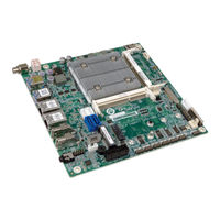
Thin Mini-ITX SBC with 14 nm Intel Atom Pentium or Celeron On-board SoC, DisplayPort++, Dual PCle GbE, USB 3.0, PCle Mini, M.2, PCle x1, SATA 6Gb/s, RS-232/422/485, Audio, TPM and RoHS
Brand:
IEI Technology
| Category:
Motherboard
| Size: 6.86 MB
Table of Contents
Table of Contents
5
Introduction
15
Introduction
16
Figure 1-1: Tkino-AL
16
Model Variations
17
Features
17
Table 1-1: Tkino-AL Model Variations
17
Connectors
18
Figure 1-2: Connectors (Front Side)
18
Figure 1-3: Connectors (Solder Side)
19
Dimensions
20
Figure 1-4: Dimensions (MM)
20
Data Flow
21
Figure 1-5: Data Flow Diagram
21
Technical Specifications
22
Table 1-2: Technical Specifications
24
Unpacking
25
Anti-Static Precautions
26
Unpacking Precautions
26
Packing List
27
Optional Items
28
Connectors
29
Peripheral Interface Connectors
30
Tkino-AL Layout
30
Figure 3-1: Connector and Jumper Locations (Front)
30
Peripheral Interface Connectors
31
External Interface Panel Connectors
32
Table 3-1: Peripheral Interface Connectors
32
Table 3-2: Rear Panel Connectors
32
Internal Peripheral Connectors
33
DC-IN Power Connector
33
Figure 3-2: DC-IN Power Connector Location
33
Table 3-3: DC-IN Power Connector Pinouts
33
Audio Connector
34
Figure 3-3: Audio Connector Location
34
Table 3-4: Audio Connector Pinouts
34
Battery Connector
35
Figure 3-4: Battery Connector Location
35
Table 3-5: Battery Connector Pinouts
35
Digital I/O Connector
36
Figure 3-5: Digital I/O Connector Location
36
Table 3-6: Digital I/O Connector Pinouts
36
Edp Connector
37
Figure 3-6: Edp Connector Location
37
Fan Connectors
38
Figure 3-7: Fan Connector Locations
38
Table 3-7: Edp Connector Pinouts
38
Front Panel Connector
39
Figure 3-8: Front Panel Connector Location
39
Table 3-8: Fan Connector Pinouts
39
Keyboard and Mouse Connector
40
Figure 3-9: Keyboard and Mouse Connector Location
40
Table 3-9: Front Panel Connector Pinouts
40
LAN LED Connectors
41
Figure 3-10: LAN LED Connector Locations
41
Table 3-10: Keyboard and Mouse Connector Pinouts
41
Slot
42
Figure 3-11: M.2 Slot Location
42
Table 3-11: LAN LED Connector Pinouts
42
Microsd Slot (Optional)
43
Pcie Mini Card Slot
43
Figure 3-12: Microsd Card Slot Location
43
Figure 3-13: Pcie Mini Card Slot Location
44
Pcie X1 Card Slot
45
Figure 3-14: Pcie X1 Slot Location
45
Table 3-12: Pcie Mini Card Slot Pinouts
45
Serial Port Connector
46
Table 3-13: Pcie X1 Slot Pinouts
46
Figure 3-15: RS-232 Serial Port Connector Locations
47
Table 3-14: RS-232 Serial Port Connector Pinouts
47
RS-232/422/485 Serial Port Connector
48
Figure 3-16: RS-232/422/485 Connector Locations
48
Table 3-15: RS-232/422/485 Connector Pinouts
48
SATA 6Gb/S Drive Connectors
49
Figure 3-17: SATA 6Gb/S Drive Connectors Locations
49
SATA Power Connectors
50
Figure 3-18: SATA Power Connector Locations
50
Table 3-16: SATA Power Connector Pinouts
50
SIM Card Slot
51
Figure 3-19: SIM Card Slot Location
51
Speaker Connector
52
Figure 3-20: Speaker Connector Location
52
Table 3-17: Speaker Connector Pinouts
52
SPI Flash Connector, BIOS
53
Figure 3-21: SPI Flash Connector Location
53
Table 3-18: SPI Flash Connector Pinouts
53
TPM Connector
54
Figure 3-22: TPM Connector Location
54
Table 3-19: TPM Connector Pinouts
54
USB Connector
55
Figure 3-23: USB Connector Location
55
Table 3-20: USB Connector Pinouts
55
External Peripheral Interface Connector Panel
56
Audio Jack
56
Figure 3-24: External Peripheral Interface Connector
56
Displayport++ Connectors
57
Table 3-21: Audio Jack Pinouts
57
Table 3-22: Displayport++ Connector Pinouts
57
LAN Connectors
58
Figure 3-25: Displayport++ Connector Pinout Locations
58
Figure 3-26: LAN Connector
58
Table 3-23: LAN Pinouts
58
Power Connector
59
USB Connectors
59
Figure 3-27: Power Jack
59
Table 3-24: Connector Leds
59
Table 3-25: USB 3.0 Port Pinouts
60
Installation
61
Anti-Static Precautions
62
Installation Considerations
62
So-DIMM Installation
64
Figure 4-1: SO-DIMM Installation
64
Module Installation
65
Figure 4-2: Removing the M.2 Module Retention Screw and Plastic Ring
65
Figure 4-3: Inserting the M.2 Module into the Slot at an Angle
66
Figure 4-4: Securing the M.2 Module
66
Pcie Mini Card Installation
67
Full-Size Pcie Mini Card Installation
67
Figure 4-5: Removing the Retention Screw
67
Figure 4-6: Inserting the Full-Size Pcie Mini Card into the Slot at an Angle
68
Figure 4-7: Securing the Full-Size Pcie Mini Card
68
Half-Size Pcie Mini Card Installation
69
Figure 4-8: Removing Retention Screw and Standoff
69
Figure 4-9: Installing the Standoff
70
Figure 4-10: Inserting the Half-Size Pcie Mini Card into the Slot at an Angle
70
Sim Card Installation
71
Figure 4-11: Securing the Half-Size Pcie Mini Card
71
Figure 4-12: Unlock SIM Card Slot Cover
71
Figure 4-13: SIM Card Installation
72
Figure 4-14: Lock SIM Card Slot Cover
72
System Configuration
73
AT/ATX Mode Select Switch
73
Figure 4-15: AT/ATX Mode Select Switch Location
73
Table 4-1: AT/ATX Mode Select Switch Settings
73
Clear CMOS Button
74
COM1 and COM2 Port Function Select Switch
74
Figure 4-16: Clear CMOS Button Location
74
Table 4-2: COM1 and COM2 Function Select Switch Settings
74
Erp Mode Setup Jumper
75
Figure 4-17: COM1 and COM2 Function Select Switch Location
75
Figure 4-18: Erp Mode Setup Jumper Location
75
Table 4-3: Erp Mode Setup Jumper Settings
75
Flash Descriptor Security Override Jumper
76
Figure 4-19: Flash Descriptor Security Override Jumper Location
76
Table 4-4: Flash Descriptor Security Override Jumper Settings
76
And SATA2 Select Switch
77
Figure 4-20: M.2 and SATA2 Select Switch Location
77
Chassis Installation
78
Airflow
78
Motherboard Installation
78
Sata Drive Connection
78
Figure 4-21: SATA Drive Cable Connection
79
Bios
80
Introduction
81
Starting Setup
81
Using Setup
81
Getting Help
82
Unable to Reboot after Configuration Changes
82
BIOS Menu Bar
82
Main
83
Advanced
84
Trusted Computing
85
ACPI Settings
86
F81866 Super IO Configuration
87
Serial Port N Configuration
87
Serial Port N Configuration
88
Hardware Monitor
88
Smart Fan Mode Configuration
89
RTC Wake Settings
91
Serial Port Console Redirection
92
CPU Configuration
93
USB Configuration
95
IEI Feature
96
SATA Configuration
97
Chipset
98
North Bridge Configuration
99
Intel IGD Configuration
99
South Bridge Configuration
102
HD-Audio Configuration
104
PCI Express Configuration
105
Rtl8111Gn Lan
105
Pcie X1 Slot (PCIE1 Slot)
106
Mini-Pcie Slot (MPCIE1 Slot)
107
Security
108
Boot
109
Save & Exit
111
Software Drivers
113
Software Installation
114
Figure 6-1: Driver CD Main Menu
115
Figure 6-2: Available Drivers
115
Available Software Drivers
116
A Regulatory Compliance
117
B Product Disposal
119
C Bios Menu Options
121
D Terminology
124
E Digital I/O Interface
128
F Watchdog Timer
131
G Hazardous Materials Disclosure
134
Advertisement
IEI Technology tKINO-AL-N1-R10 Quick Installation Manual (12 pages)
tKINO-AL series. Thin Mini-ITX SBC supports Intel 14nm Atom , Pentium or Celeron on-board SoC with DP++, Dual PCIe GbE, USB 3.0, PCIe Mini, M.2, SATA 6Gb/s, COM, Audio and RoHS
Brand:
IEI Technology
| Category:
Motherboard
| Size: 0.37 MB
Advertisement
Related Products
IEI Technology tKINO-AL-N2-R10
IEI Technology tKINO-AL-E3-R10
iEi Integration tKINO-AL-E2-R10
iEi Integration tKINO-AL-E1-R10
IEI Technology tKINO-AL
IEI Technology tKINO-BW Series
IEI Technology tKINO-BW-N4-R10
IEI Technology tKINO-BW-N3-R10
IEI Technology tKINO-BW-N2-R10
IEI Technology tKINO-BW-N1-R10
IEI Technology Categories
Motherboard
Touch Panel
Computer Hardware
Single board computers
Desktop
More IEI Technology Manuals
Login
Sign In
OR
Sign in with Facebook
Sign in with Google
Upload manual
Upload from disk
Upload from URL