Sign In
Upload
Manuals
Brands
IEI Technology Manuals
Computer Hardware
ROCKY-4786EV
IEI Technology ROCKY-4786EV Manuals
Manuals and User Guides for IEI Technology ROCKY-4786EV. We have
1
IEI Technology ROCKY-4786EV manual available for free PDF download: User Manual
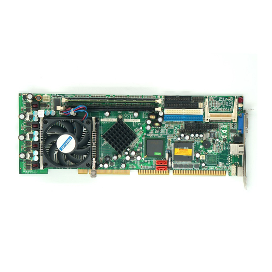
IEI Technology ROCKY-4786EV User Manual (145 pages)
PICMG Socket 478 CPU Card, Intel Pentium 4 Processor Support, Gigabit Ethernet, USB 2.0, VGA, SATA RoHS Compliant
Brand:
IEI Technology
| Category:
Computer Hardware
| Size: 6 MB
Table of Contents
Table of Contents
4
1 Introduction
11
Rocky-4786Ev/Evg Cpu Board Overview
12
ROCKY-4786EV/EVG CPU Board Applications
12
ROCKY-4786EV/EVG CPU Board Benefits
12
ROCKY-4786EV/EVG CPU Board Features
12
Connectors
13
Dimensions
13
Figure 1-1 Connectors
13
Figure 1-2: ROCKY-4786EV/EVG Dimensions (MM)
14
Data Flow
15
Figure-1-3: Data Flow Block Diagram
15
Technical Specifications
16
Table-1-1: Technical Specifications
17
2 Unpacking
18
Anti-Static Precautions
19
Unpacking Precautions
19
Packing List
20
Optional Items
21
3 Connectors
23
Peripheral Interface Connectors
24
Figure 3-1: Connector and Jumper Locations
24
ROCKY-4786EV/EVG CPU Board Layout
24
Peripheral Interface Connectors
25
Rear Panel Connectors
26
Internal Peripheral Connectors
26
FDD Connector
26
Table 3-1: Peripheral Interface Connectors
26
Table 3-2: Peripheral Interface Connectors
26
Table 3-3: FDD Connector Pinouts
27
Figure 3-2: FDD Connector Location
28
IDE Connectors
29
Table 3-4: IDE Connector Pinouts
29
Figure 3-3: IDE Connector Locations
30
COM Ports
31
Table-3-5: Internal COM Port Connector Pinouts
31
Figure 3-4 COM Port Locations
32
Parallel Port
32
Table-3-6: LPT Connector Pinouts
33
Figure-3-5: LPT Connector Location
34
Internal USB Connectors
35
Table-3-7: USB Port Connector Pinouts
35
Figure-3-6: USB Port Connector Location
36
Cooling Fan Connector
37
Table 3-8 Cooling Fan Connector Pinouts
37
Backplane to Mainboard ATX Connector
38
Figure 3-7 Cooling Fan Connector Locations
38
Table 3-9: CN7 Connector Pin Outs
39
Figure 3-8: ATXCTL Connector Locations
40
System Front Panel Connector
41
Table 3-10: System Panel Connector Pinouts
41
Figure 3-9: System Panel Connector Location
42
Irda Connector
42
Table 3-11: Irda Connector Pinouts
43
Figure 3-10: Irda Connector Location
44
SATA Drive Connectors
44
Table 3-12: SATA Connector Pinouts
45
Figure 3-11: SATA Connector Locations
46
Keyboard Connector
47
Table 3-13: CN5 Connector Pinouts
47
Figure 3-12: CN5 Connector Location
48
ATX-12V Power Source Connector
49
Table 3-14: CN2 Connector Pinouts
49
External (Rear Panel) Connectors
50
Figure 3-13: ATX Connector Location
50
Figure 3-14: ROCKY-4786EV/EVG CPU Board Rear Panel
51
PS/2 Connector
51
Ethernet Connectors
52
Figure 3-15: PS/2 Pinout Locations
52
Table 3-15: PS/2 Pinouts
52
Figure 3-16: RJ-45 Ethernet Connector
53
LINE out Connector
53
Table 3-16: RJ-45 Ethernet Connector Pinouts
53
Table 3-17: RJ-45 Ethernet Connector Leds
53
Figure 3-17: VGA Connector
54
Table 3-18: VGA Connector Pinouts
54
VGA Connector
54
4 Installation
55
Anti-Static Precautions
56
Installation Considerations
56
Rocky-4786Ev/Evg Cpu Card Installation
58
CPU Installation
59
Cooling Kit CF-519 Installation
60
Figure 4-1: Locking the CPU into the CPU Socket
60
DIMM Module Installation
61
Figure 4-2: Cooling Kit Support Bracket
61
Purchasing the Memory Module
61
Backplane Installation
62
CPU Card Installation
62
DIMM Module Installation
62
Jumper Settings
63
Table 4-1: Jumpers
63
Figure 4-3: Jumper Locations
64
CF Card Setup
65
Reset CMOS Jumper
65
Table 4-2: Compactflash® Setup Jumper Settings
65
Internal Peripheral Device Connections
66
IDE Disk Drive Connector (IDE1)
66
Table 4-3: Reset CMOS Jumper Settings
66
Floppy Drive Connector (FDD1)
67
External Peripheral Interface Connection
67
Audio Line-Out Connector
67
Figure 4-4: LAN Connection
68
LAN Connection
68
VGA Monitor Connection
68
Software Installation
69
Figure 4-5: VGA Connector
69
Figure 4-6: Introduction Screen
70
Figure 4-7: Available Drivers
71
5 Award Bios Setup
72
Introduction
73
Starting Setup
73
Using Setup
73
Getting Help
74
Table 5-1: BIOS Navigation Keys
74
Unable to Reboot after Configuration Changes
74
Main BIOS Menu
75
Load Fail-Safe Defaults
76
Load Optimized Defaults
76
Set Supervisor Password
76
Set User Password
76
Save & Exit Setup
76
Standard Cmos Features
77
Exit Without Saving
77
IDE Master and IDE Slave
77
Drive a [1.44M, 3.5In]
78
Drive B [1.44M, 3.5In]
78
Video [EGA/VGA]
78
Ega
79
Vga
79
Sega
79
Svga
79
Pga
79
Halt on
79
Base Memory
79
IDE Channel Master
80
Extended Memory
80
Total Memory
80
IDE HDD Auto-Detection [Press Enter]
80
IDE Channel 0/1 Master/Slave [Auto]
81
Access Mode [Auto]
81
Advanced Bios Features
82
Capacity
82
Cylinder
82
Head
82
Precomp
82
Landing Zone
82
Sector
82
Virus Warning [Disabled]
83
CPU L1 & L2 Cache [Enabled]
84
Quick Power on Self Test [Enabled]
84
Boot Device
84
Boot Other Device [Enabled]
85
Swap Floppy Drive [Disabled]
85
Boot up Floppy Seek [Enabled]
86
Boot up Numlock Status [On]
86
Gate A20 Option [Fast]
86
Typematic Rate Setting [Disabled]
86
Typematic Rate (Chars/Sec) [6]
87
Typematic Delay (Msec) [250]
87
Security Option [Setup]
87
APIC Mode [Enabled]
88
MPS Version Control for os [1.4]
88
CPU Feature
89
OS Select for DRAM > 64MB [Non-OS2]
89
Small Logo (EPA) Show [Disabled]
89
Thermal Management [Thermal Monitor 1]
90
Hard Disk Boot Priority
91
Advanced Chipset Features
92
DRAM Timing Selectable [Manual]
92
CAS Latency Time [2]
93
Active to Precharge Delay [6]
93
DRAM RAS# to CAS# Delay [3]
93
DRAM RAS# Precharge [3 Clocks]
93
Memory Frequency for [DDR266]
94
System BIOS Cacheable [Enabled]
94
Video BIOS Cacheable [Disabled]
94
Memory Hole at 15M - 16M [Disabled]
94
Delay Prior to Thermal [16 Min.]
95
AGP Aperture Size (MB) [128]
95
Init Display First [PCI Slot]
96
On-Chip VGA [Enabled]
96
On-Chip Frame Buffer Size [16MB]
96
Boot Display [Auto]
96
Integrated Peripherals
97
Onchip IDE Device
97
IDE HDD Block Mode [Enabled]
98
On-Chip Primary PCI IDE [Enabled]
98
IDE PIO [Auto]
98
IDE UDMA [Auto]
99
On-Chip Secondary PCI IDE [Auto]
99
Onboard Device
100
On Chip Serial ATA [Disabled]
100
PATA IDE Mode [Secondary]
100
SATA Port
100
USB Controller [Enabled]
101
USB 2.0 Controller [Enabled]
101
USB Keyboard Support [Disabled]
101
Superio Device
102
AC97 Audio Select [Auto]
102
I82562ET LAN (10/100M) [Disabled]
102
POWER on Function [BUTTON ONLY]
103
KB Power on Password [Enter]
104
Hot Key Power on [Ctrl-F1]
104
Onboard FDC Controller [Disabled]
104
Onboard Serial Port 1 [3F8/IRQ4]
105
Onboard Serial Port 2 [2F8/IRQ4]
105
UART Mode Select [Normal]
105
Rxd, Txd Active [Hi,Lo]
106
IR Transmission Delay [Enabled]
106
UR2 Duplex Mode [Half]
106
Use IR Pins [IR-Rx2Tx2]
106
Onboard Parallel Port [378/IRQ7]
106
Parallel Port Mode [SPP]
107
EPP Mode Select
107
ECP Mode Use DMA [3]
107
Power Management Setup
108
PWRON after PWR-Fail [Off]
108
Watch Dog Timer Unit [Second]
108
Power-Supply Type [AT]
109
ACPI Function [Enabled]
109
ACPI Suspend Type [S1(POS)]
109
Run VGABIOS if S3 Resume [Auto]
110
Power Management [User Define]
110
Video off Method [DPMS]
111
Video off in Suspend [Yes]
111
Suspend Type [Stop Grant]
111
MODEM Use IRQ [3]
112
Suspend Mode [Disabled]
112
HDD Power down [Disabled]
113
Soft -Off by PWR-BTTN [Instant-Off]
113
Wake-Up on LAN(I82562ET) [Enabled]
114
Power on by Ring [Enabled]
114
USB KB Wake-Up from S3 [Disabled]
114
Resume by Alarm [Disabled]
115
Date(Of Month) Alarm [0]
115
Time(Hh:MM:ss) Alarm [0 : 0 : 0]
115
Pnp/Pci Configurations
116
Reload Global Timer Events
116
PNP os Installed [No]
117
Reset Configuration Data [Disabled]
117
Resources Controlled by [Auto (ESCD)]
117
IRQ Resources [Press Enter]
117
DMA Resources [Press Enter]
119
Pc Health Status
120
PCI/VGA Palette Snoop [Disabled]
120
Frequency/Voltage Control
121
System Temperature
121
Voltages
121
Fan Speeds
121
Auto Detect DIMM/PCI Clk [Enabled]
122
Spread Spectrum [Disabled]
122
ABIOS Options
124
Page 115
125
B Terminology
129
C Digital I/O Interface
133
Introduction
134
Dio Connector Pinouts
134
Assembly Language Samples
135
Enable the DIO Input Function
135
Enable the DIO Output Function
135
D Watchdog Timer
136
E Address Mapping
139
I/O Address Map
140
St Mb Memory Address Map
140
Irq Mapping Table
141
Dma Channel Assignments
141
Advertisement
Advertisement
Related Products
IEI Technology ROCKY-3786EV
IEI Technology ROCKY-4786EVG
IEI Technology ROCKY-3786EVGU2
IEI Technology Rocky-3702EV
IEI Technology ROCKY-6614
IEI Technology ROCKY-538TXV
IEI Technology ROCKY-4783EV Series
IEI Technology ROCKY-558EV
IEI Technology ROCKY-6160
IEI Technology Robot-TP-65M
IEI Technology Categories
Motherboard
Touch Panel
Computer Hardware
Single board computers
Desktop
More IEI Technology Manuals
Login
Sign In
OR
Sign in with Facebook
Sign in with Google
Upload manual
Upload from disk
Upload from URL