Sign In
Upload
Manuals
Brands
IEI Technology Manuals
Industrial PC
PPC-3708
IEI Technology PPC-3708 Manuals
Manuals and User Guides for IEI Technology PPC-3708. We have
1
IEI Technology PPC-3708 manual available for free PDF download: User Manual
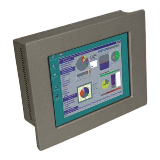
IEI Technology PPC-3708 User Manual (161 pages)
Brand:
IEI Technology
| Category:
Industrial PC
| Size: 3 MB
Table of Contents
Table of Contents
8
Introduction
15
Overview
16
Model Variation
16
PPC-3708 Model Variation
16
PPC-3710 Model Variation
17
Table 1-1: PPC-3708 Model Variation
17
PPC-3712 Model Variation
18
Table 1-2: PPC-3710 Model Variation
18
Table 1-3: PPC-3712 Model Variation
19
Features
19
Applications
19
External Overview
20
General Description
20
Front Panel
20
Figure 1-1: Front View
20
Rear Panel
21
Bottom Panel
21
PPC-3708 Bottom Panel
21
Figure 1-2: PPC-3712 Wall-Mounting Bracket Retention Screw Holes
21
PPC-3710 Bottom Panel
22
Figure 1-3: PPC-3708 Bottom View
22
PPC-3712 Bottom Panel
23
Figure 1-4: PPC-3710 Bottom View
23
Side Panel
24
Frame
24
Figure 1-5: PPC-3712 Bottom View
24
Figure 1-6: PPC-3712 Left View
24
Figure 1-8: PPC-3712 Frame Rear View (8 Panel Mount Retention Screw Holes)
25
Preinstalled Hardware Components
25
Figure 1-7: PPC-3710 Frame Rear View (10 Panel Mount Retention Screw Holes)
25
Specifications
25
System Specifications
26
Motherboard Specifications
27
Table 1-4: System Specifications
27
Flat Panel Screen Specifications
28
PPC-3708 Flat Panel Screen
28
Table 1-5: Motherboard Specifications
28
Table 1-6: 8.4" TFT LCD Monitor Specifications
29
PPC-3710 Flat Panel Screen
29
PPC-3712 Flat Panel Screen
30
Table 1-7: 10.4" TFT LCD Monitor Specifications
30
Power Adapter Specifications
31
Power Adapter
31
Figure 1-9: 80W Power Adapter Dimensions
31
Table 1-8: 12.1" TFT LCD Monitor Specifications
31
Table 1-9: 80W Power Adapter Specifications
33
Figure 1-10: 60W Power Adapter Dimensions
33
Power Adapter
33
Power Module Specifications
34
Table 1-10: 60W Power Adapter Specifications
34
Table 1-11: DC-To-DC Power Module Specifications
35
Dimensions
36
PPC-3708 Dimensions
36
Figure 1-11: PPC-3708 Dimensions (Units in MM)
36
PPC-3710 Dimensions
37
Figure 1-12: PPC-3710 Dimensions (Units in MM)
37
PPC-3712 Dimensions
38
Figure 1-13: PPC-3712 Dimensions (Units in MM)
38
Nano-8522 Motherboard
39
Introduction
40
Cpu Support
40
Onboard Chipsets
40
Northbridge and Southbridge Chipsets
40
852GM Northbridge Chipset
40
ICH4 Southbridge Chipset
41
Graphics Support
42
Peripheral Device Interfaces, Connectors, and Slots
43
OEM Options
43
Internal Slots
44
Internal Peripheral Device Connectors
44
External Peripheral Device Connectors
44
Installation and Configuration
47
Installation Precautions
48
Preinstalled Components
48
Installation and Configuration Steps
48
Unpacking
49
Packing List
50
Jumper Settings
50
Figure 3-1: Jumper Locations
51
Remove the
52
PPC-3708 Back Cover Removal
52
PPC-3710 Back Cover Removal
52
Figure 3-2: PPC-3708 Back Cover Retention Screws
52
Figure 3-3: PPC-3710 Back Cover Retention Screws
52
Figure 3-4: PPC-3712 Back Cover Retention Screws
53
Table 3-1: CF Card Setup Jumper Settings
53
JP1: CF Card Setup
53
JP4: Clear CMOS Setup
53
PPC-3712 Back Cover Removal
53
JP6: LCD Voltage Setup
54
JP2: COM Port Jumper Setting
54
Table 3-2: Clear CMOS Jumper Settings
54
Table 3-3: LCD Voltage Setup Jumper Settings
54
Table 3-4: JP2 Jumper Settings
55
CPU Installation
55
Cpu and Cpu Cooler Installation
55
Figure 3-5: Make Sure the CPU Socket Retention Screw Is Unlocked
56
Cooling Kit (CF-479B-RS) Installation
57
Figure 3-6: Lock the CPU Socket Retention Screw
57
Figure 3-7: IEI CF-479B-RS Cooling Kit
57
Figure 3-8: Securing the Cooling Kit
58
Hdd Installation
59
PPC-3708 HDD Installation
59
Figure 3-9: Connect the Cooling Fan Cable
59
Figure 3-12: PPC-3708 HDD Retention Screws
60
Figure 3-10: PPC-3708 HDD Bracket Retention Screws (Tope Panel)
60
Figure 3-11: PPC-3708 HDD Bracket Retention Screws (Inside)
60
PPC-3710 HDD Installation
61
Figure 3-13: PPC-3710 HDD Bracket Retention Screws
62
Figure 3-14: PPC-3710 HDD Retention Screws
62
PPC-3712 HDD Installation
63
Figure 3-15: PPC-3712 HDD Bracket Retention Screws
63
Figure 3-17: CD Drive Adapter Installation
64
Figure 3-16: PPC-3712 HDD Retention Screws
64
CD Drive Installation (PPC-3712 Only)
64
Figure 3-18: CD Drive Bracket Retention Screws
65
Figure 3-19: PPC-3712 CD Drive Retention Screws
65
Mounting the System
66
Wall Mounting
66
Figure 3-20: Wall-Mounting Bracket
67
Figure 3-21: Mount the Chassis
68
Figure 3-22: Secure the Chassis
69
PPC-3708/PPC-3710 Panel Mounting
69
Panel Mounting
69
Figure 3-24: Suggested Panel Cut out Size for PPC-3710
70
Figure 3-23: Suggested Panel Cut out Size for PPC-3708
70
PPC-3712 Panel Mounting
71
Figure 3-25: Tighten the Panel Mounting Clamp Screws (PPC-3708/PPC-3710)
71
Figure 3-26: PPC-3712 Panel Mounting Kit
71
Figure 3-27: Suggested Panel Cut out Size for PPC-3712
72
Arm Mounting
73
Figure 3-28: Tighten the Panel Mounting Clamp Screws (PPC-3712)
73
Figure 3-29: Arm Mounting Retention Screw Holes
74
Cabinet and Rack Installation
74
PPC-3708 Cabinet and Rack Installation
74
Figure 3-31: Secure the PPC-3708 Rack/Cabinet Bracket
75
Figure 3-30: the Rack/Cabinet Bracket
75
PPC-3710/PPC-3712 Cabinet and Rack Installation
76
Figure 3-32: Install into a Rack/Cabinet
76
Rear Panel Connectors
77
LCD Panel Connection
77
Figure 3-33: Secure the PPC-3710/PPC-3712 Rack/Cabinet Bracket
77
System Maintenance
78
Ethernet Connection
78
Keyboard and Mouse Connection
78
USB Connection
78
Ami Bios Setup
79
Introduction
80
Starting Setup
80
Using Setup
80
Table 4-1: BIOS Navigation Keys
81
Getting Help
81
BIOS Menu Bar
81
Unable to Reboot after Configuration Changes
81
Main
82
BIOS Menu 1: Main
82
System Overview
82
Advanced
83
System Time [XX:XX:XX]
83
System Date [XX/XX/XX]
83
BIOS Menu 2: Advanced
84
CPU Configuration
84
BIOS Menu 3: CPU Configuration
85
Hyper Threading Technology [Enabled]
85
IDE Configuration
86
BIOS Menu 4: IDE Configuration
86
Onboard PCI IDE Controller [Both]
86
Onboard PCI IDE Mode [Legacy Mode]
87
Hard Disk Write Protect [Disabled]
87
IDE Detect Time out (Sec) [35]
87
ATA (PI) 80Pin Cable Detection [Host & Device]
88
IDE Master and IDE Slave
88
IDE Master, IDE Slave
89
BIOS Menu 5: IDE Master and IDE Slave Configuration
89
Auto-Detected Drive Parameters
90
Type [Auto]
90
Zip
91
Lba/Large Mode [Auto]
91
Block (Multi Sector Transfer) [Auto]
91
Auto
92
DMA Mode [Auto]
92
PIO Mode [Auto]
92
Floppy Configuration
93
32Bit Data Transfer [Disabled]
93
BIOS Menu 6: Floppy Configuration
93
Super IO Configuration
94
Floppy a [Disabled]
94
BIOS Menu 7: Super IO Configuration
94
Serial Port2 Mode [Normal]
95
Serial Port1 Address [3F8/IRQ4]
95
Serial Port2 Address [2F8/IRQ3]
95
On Board Floppy Controller [Enabled]
95
Parallel Port Address [378]
96
Parallel Port Mode [Normal]
96
Parallel Port IRQ [IRQ7]
97
Serial Port3 Address [3E8]
97
Serial Port4 IRQ [10]
98
Serial Port4 Address [2E8]
98
Serial Port3 IRQ [11]
98
Hardware Health Configuration
99
BIOS Menu 8: Hardware Health Configuration
99
MPS Configuration
100
BIOS Menu 9: MPS Configuration
100
Smbios Configuration
101
MPS Revision [1.4]
101
BIOS Menu 10: Smbios Configuration
101
Smbios Smi Support [Enabled]
101
BIOS Menu 11: USB Configuration
102
USB Configuration
102
USB Function [6 USB Ports]
103
Legacy USB Support [Enabled]
103
USB 2.0 Controller [Enabled]
103
USB Devices Enabled
103
Pci/Pnp
104
USB2.0 Controller Mode [Hispeed]
104
BIOS EHCI Handoff [Enable]
104
USB Mass Storage Device Configuration
104
Plug & Play O/S [No]
105
BIOS Menu 12: Pci/Pnp Configuration
105
Clear NVRAM [No]
105
PCI Latency Timer [64]
106
Allocate IRQ to PCI VGA [Yes]
106
Palette Snooping [Disabled]
106
PCI IDE Busmaster [Disabled]
107
Offboard PCI/ISA IDE Card [Auto]
107
IRQ# [Available]
108
DMA Channel# [Available]
109
Reserved Memory Size [Disabled]
109
BIOS Menu 13: Boot
110
Boot
110
Boot Settings Configuration
110
Quick Boot [Enabled]
111
Quiet Boot [Disabled]
111
BIOS Menu 14: Boot Settings Configuration
111
Addon ROM Display Mode [Force BIOS]
112
Bootup Num-Lock [On]
112
PS/2 Mouse Support [Auto]
112
Wait for 'F1' if Error [Enabled]
113
Hit 'DEL' Message Display [Enable]
113
Interrupt 19 Capture [Disabled]
113
Security
114
BIOS Menu 15: Security
114
Change Supervisor Password
114
Clear User Password
115
Boot Sector Virus Protection [Disabled]
115
Change User Password
115
Chipset
115
Northbridge Configuration
116
BIOS Menu 16: Chipset
116
BIOS Menu 17:Northbridge Chipset Configuration
117
DRAM Frequency [Auto]
117
Configure DRAM Timing by SPD [Enabled]
117
Memory Hole [Disabled]
118
Init. Graphic Adapter Priority [Internal VGA]
118
Boot Display Device [Auto]
119
Internal Graphics Mode Select [Enable, 8MB]
119
Graphics Aperture Size [64MB]
119
Flat Panel Type [800X600 18 Bit LVDS]
120
South Bridge Configuration
121
Local Flat Panel Scaling [Auto]
121
Power Key
122
BIOS Menu 18:Southbridge Chipset Configuration
122
Onboard AC97 Audio DEVICE
122
Restore on AC Power Loss [Last State]
122
Video Power down Mode [Suspend]
123
BIOS Menu 19:Power
123
Power Management/Apm [Enabled]
123
Hard Disk Power down Mode [Suspend]
124
Standby Time out [Disabled]
124
Suspend Time out [Disabled]
125
Throttle Slow Clock Ratio [50%]
125
Keyboard & PS/2 Mouse [MONITOR]
126
FDC/LPT/COM Ports [MONITOR]
126
Primary Master IDE [MONITOR]
126
Primary Slave IDE [MONITOR]
127
Secondary Master IDE [MONITOR]
127
Secondary Slave IDE [MONITOR]
128
System Thermal [Disabled]
128
Power Button Mode [On/Off]
128
Resume on Ring [Disabled]
129
Resume on Lan [Disabled]
129
Resume on PME# [Disabled]
129
Resume on RTC Alarm [Disabled]
129
BIOS Menu 20:Exit
130
Exit
130
System Time
130
RTC Alarm Date (Days)
130
Save Changes and Exit
131
Discard Changes and Exit
131
Discard Changes
131
Load Optimal Defaults
131
Load Failsafe Defaults
131
Ainterface Connectors
133
Peripheral Interface Connectors
134
Bbios Configuration Options
143
Bios Configuration Options
143
B.1 BIOS Configuration Options
144
Csoftware Drivers
149
Driver Installation
150
Introduction
150
Touch Panel Driver Configuration
157
Dindex
159
Advertisement
Advertisement
Related Products
IEI Technology PPC-3710
IEI Technology PPC-3712
IEI Technology PPC-F17C-Q370
IEI Technology PPC-F15A-H81i-i3/4G/R-R10
IEI Technology PPC-F15A-H81i-i3/4G/PC-R10
IEI Technology PPC-F17AA-H81i-P/4G/PC-R10
IEI Technology PPC-F17AA-H81i-i3/4G/PC-R10
IEI Technology PPC-F17AA-H81i-i5/4G/R-R10
IEI Technology PPC-F22AA-H81i-i5/4G/PC-R10
IEI Technology PPC-F24AA-H81i-i3/4G/PC-R10
IEI Technology Categories
Motherboard
Touch Panel
Computer Hardware
Single board computers
Desktop
More IEI Technology Manuals
Login
Sign In
OR
Sign in with Facebook
Sign in with Google
Upload manual
Upload from disk
Upload from URL