Sign In
Upload
Manuals
Brands
IEI Technology Manuals
Motherboard
IMB-Q870-i2
User Manuals: IEI Technology IMB-Q870-i2 Motherboard
Manuals and User Guides for IEI Technology IMB-Q870-i2 Motherboard. We have
1
IEI Technology IMB-Q870-i2 Motherboard manual available for free PDF download: User Manual
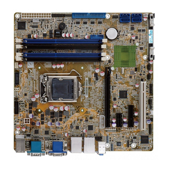
IEI Technology IMB-Q870-i2 User Manual (223 pages)
microATX Motherboard with LGA1150 Intel core i7/i5/i5, pentium or celeron CPU, Intel Q87 chipset, dual gbe , DDR3, DVI,HDMI
Brand:
IEI Technology
| Category:
Motherboard
| Size: 11.52 MB
Table of Contents
User Manual
1
Table of Contents
4
1 Introduction
17
Introduction
18
Benefits
18
Figure 1-1: IMB-Q870-I2
18
Features
19
Connectors
20
Figure 1-2: Connectors
20
Dimensions
21
Figure 1-3: IMB-Q870-I2 Dimensions (MM)
21
Data Flow
22
Figure 1-4: Data Flow Diagram
22
Technical Specifications
23
Table 1-1: IMB-Q870-I2 Specifications
24
2 Packing List
25
Anti-Static Precautions
26
Unpacking Precautions
26
Packing List
27
Optional Items
28
Table 2-1: Packing List
28
Table 2-2: Optional Items
30
3 Connectors
31
Peripheral Interface Connectors
32
IMB-Q870-I2 Layout
32
Figure 3-1: Connectors and Jumpers
32
Peripheral Interface Connectors
33
External Interface Panel Connectors
34
Table 3-1: Peripheral Interface Connectors
34
Table 3-2: Rear Panel Connectors
34
Internal Peripheral Connectors
35
ATX Power Connector
35
Figure 3-2: ATX Power Connector Location
35
Battery Connector
36
Table 3-3: ATX Power Connector Pinouts
36
Chassis Intrusion Connector
37
Figure 3-3: Battery Connector Location
37
Table 3-4: Battery Connector Pinouts
37
CPU Power Connector
38
Figure 3-4: Chassis Intrusion Connector Location
38
Table 3-5: Chassis Intrusion Connector Pinouts
38
Displayport Connector
39
Figure 3-5: CPU Power Connector Location
39
Table 3-6: CPU Power Connector Pinouts
39
Digital I/O Connector
40
Figure 3-6: Displayport Connector Location
40
Table 3-7: Displayport Connector Pinouts
40
EC Debug Connector
41
Figure 3-7: Digital I/O Connector Location
41
Table 3-8: Digital I/O Connector Pinouts
41
Fan Connector (CPU)
42
Figure 3-8: EC Debug Connector Location
42
Table 3-9: EC Debug Connector Pinouts
42
Fan Connectors (System)
43
Figure 3-9: CPU Fan Connector Location
43
Table 3-10: CPU Fan Connector Pinouts
43
Front Panel Audio Connector
44
Figure 3-10: System Fan Connector Locations
44
Table 3-11: System Fan Connector Pinouts
44
Front Panel Connector
45
Figure 3-11: Front Panel Audio Connector Location
45
Table 3-12: Front Panel Audio Connector Pinouts
45
Iris Module Slot
46
Figure 3-12: Front Panel Connector Location
46
Table 3-13: Front Panel Connector Pinouts
46
Keyboard and Mouse Connector
47
Figure 3-14: Iris Module Slot Location
47
LAN LED Connectors
48
Figure 3-15: Keyboard and Mouse Location
48
Table 3-15: Keyboard and Mouse Connector Pinouts
48
Memory Card Slots
49
Figure 3-16: LAN LED Connector Locations
49
Table 3-16: LAN1 LED Connector (LED_LAN1) Pinouts
49
Table 3-17: LAN2 LED Connector (LED_LAN2) Pinouts
49
PCI Express Power Connector
50
Figure 3-17: Memory Card Slot Locations
50
Power Button
51
Figure 3-18: Pcie Power Location
51
Table 3-18: Pcie Power Pinouts
51
SATA 6Gb/S Drive Connectors
52
Figure 3-19: Power Button Location
52
Figure 3-20: SATA 6Gb/S Drive Connector Locations
52
Serial Port Connectors, RS-232
53
Figure 3-21: Serial Port Connector Location
53
Table 3-19: SATA 6Gb/S Drive Connector Pinouts
53
Serial Port Connector, RS-422/485
54
Table 3-20: COM3~6 Serial Port Connector Pinouts
54
Figure 3-22: RS-422/485 Connector Location
55
Table 3-21: RS-422/485 Connector Pinouts
55
Table 3-22: DB-9 RS-422/485 Pinouts
55
Smbus Connector
56
SPI Flash Connector
56
Figure 3-23: Smbus Connector Location
56
Table 3-23: Smbus Connector Pinouts
56
SPI Flash Connector, EC
57
Figure 3-24: SPI Flash Connector Location
57
Table 3-24: SPI Flash Connector Pinouts
57
TPM Connector
58
Figure 3-25: SPI EC Flash Connector Location
58
Table 3-25: SPI EC Flash Connector Pinouts
58
USB 2.0 Connectors
59
Figure 3-26: TPM Connector Location
59
Table 3-26: TPM Connector Pinouts
59
USB 3.0 Connector
60
Figure 3-27: USB 2.0 Connector Locations
60
Table 3-27: USB 2.0 Connector Pinouts
60
External Peripheral Interface Connector Panel
61
Figure 3-28: USB 3.0 Connector Location
61
Table 3-28: USB 3.0 Connector Pinouts
61
Audio Connector
62
Figure 3-29: External Peripheral Interface Connector
62
Figure 3-30: Audio Connector
62
Ethernet and USB 2.0 Connectors
63
Keyboard/Mouse and USB 2.0 Connectors
63
Table 3-29: USB 2.0 Port Pinouts
63
Table 3-30: PS/2 Connector Pinouts
63
Ethernet and USB 3.0 Connectors
64
Table 3-31: USB 2.0 Port Pinouts
64
Table 3-32: LAN2 Pinouts
64
HDMI Port Connector
65
Table 3-33: USB 3.0 Port Pinouts
65
Table 3-34: LAN1 Pinouts
65
Figure 3-31: Serial Port Connector Pinouts
66
Serial Port Connector (COM1)
66
Table 3-35: HDMI Connector Pinouts
66
Table 3-36: Serial Port Connector Pinouts
66
Figure 3-32: VGA Connector
67
Table 3-37: VGA Connector Pinouts
67
VGA and DVI Connectors
67
Figure 3-33: DVI-I Connector
68
Table 3-38: DVI Connector Pinouts
68
4 Installation
69
Anti-Static Precautions
70
Installation Considerations
70
Socket LGA1150 CPU Installation
72
Figure 4-1: Disengage the CPU Socket Load Lever
72
Figure 4-2: Remove Protective Cover
73
Figure 4-3: Insert the Socket LGA1150 CPU
74
Socket LGA1150 Cooling Kit Installation
75
Figure 4-4: Close the Socket LGA1150
75
Figure 4-5: Cooling Kits (CF-1156A-RS and CF-1156E-RS)
75
Figure 4-6: Cooling Kit Support Bracket
76
DIMM Installation
77
Figure 4-7: DIMM Installation
77
Iris-2400 Module Installation
78
Figure 4-8: Iris-2400 Module Installation
78
System Configuration
79
AT/ATX Power Mode Setting
79
Figure 4-9: AT/ATX Power Mode Switch Location
79
Clear CMOS Button
80
Flash Descriptor Security Override
80
Figure 4-10: Clear CMOS Button Location
80
Table 4-1: Flash Descriptor Security Override Jumper Settings
80
Pcie X16 Interface Setup
81
USB Power Select
81
Figure 4-11: Flash Descriptor Security Override Jumper Location
81
Table 4-2: Pcie X16 Interface Setup
81
Internal Peripheral Device Connections
82
SATA Drive Connection
82
Table 4-3: BIOS Options and Configured USB Ports
82
Figure 4-12: SATA Drive Cable Connection
83
External Peripheral Interface Connection
84
Audio Connector
84
Figure 4-13: SATA Power Drive Connection
84
DVI Display Device Connection
85
Figure 4-14: Audio Connector
85
HDMI Display Device Connection
86
Figure 4-15: DVI Connector
86
LAN Connection
87
Figure 4-16: HDMI Connection
87
PS/2 Keyboard and Mouse Connection
88
Figure 4-17: LAN Connection
88
Serial Device Connection
89
Figure 4-18: PS/2 Keyboard/Mouse Connector
89
USB Connection (Dual Connector)
90
Figure 4-19: Serial Device Connector
90
VGA Monitor Connection
91
Figure 4-20: USB Connector
91
Intel ® Amt Setup Procedure
92
Figure 4-21: VGA Connector
92
Ipmi Setup Procedure
93
Managed System Hardware Setup
93
Using the IEI Iman Web GUI
94
Figure 4-22: IEI Iman Web Address
94
Figure 4-23: IEI Iman Web GUI
95
5 Bios
96
Introduction
97
Starting Setup
97
Using Setup
97
Getting Help
98
Unable to Reboot after Configuration Changes
98
BIOS Menu Bar
98
Table 5-1: BIOS Navigation Keys
98
Main
99
Advanced
101
ACPI Settings
102
RTC Wake Settings
103
Trusted Computing
104
CPU Information
105
SATA Configuration
108
Intel(R) Rapid Start Technology
109
AMT Configuration
110
USB Configuration
111
F81866 Super IO Configuration
112
Serial Port N Configuration
113
Iwdd H/W Monitor
118
Smart Fan Mode Configuration
119
Serial Port Console Redirection
121
Iei Feature
124
Chipset
125
PCH-IO Configuration
126
Table 5-2: BIOS Options and Configured USB Ports
127
PCI Express Configuration
128
PCH Azalia Configuration
129
System Agent (SA) Configuration
130
Graphics Configuration
131
NB Pcie Configuration
134
Memory Configuration
135
Boot
136
Security
138
Exit
138
6 Software Drivers
140
Available Software Drivers
141
Software Installation
141
Figure 6-1: Introduction Screen
142
Figure 6-2: Available Drivers
142
Chipset Driver Installation
143
Figure 6-3: Chipset Driver Welcome Screen
143
Figure 6-4: Chipset Driver License Agreement
144
Figure 6-5: Chipset Driver Read Me File
144
Figure 6-6: Chipset Driver Setup Operations
145
Graphics Driver Installation
146
Figure 6-7: Chipset Driver Installation Finish Screen
146
Figure 6-8: Graphics Driver Welcome Screen
147
Figure 6-9: Graphics Driver License Agreement
147
Figure 6-10: Graphics Driver Read Me File
148
Figure 6-11: Graphics Driver Setup Operations
148
Lan Driver Installation
149
Figure 6-12: Graphics Driver Installation Finish Screen
149
Figure 6-13: Windows Control Panel
150
Figure 6-14: System Control Panel
150
Figure 6-15: Device Manager List
151
Figure 6-16: Update Driver Software Window
152
Figure 6-17: Locate Driver Files
152
Usb 3.0 Driver Installation
153
Figure 6-18: LAN Driver Installation
153
Figure 6-19: USB 3.0 Driver Welcome Screen
154
Figure 6-20: USB 3.0 Driver License Agreement
155
Figure 6-21: USB 3.0 Driver Read Me File
155
Figure 6-22: USB 3.0 Driver Setup Operations
156
Figure 6-23: USB 3.0 Driver Installation Finish Screen
156
Audio Driver Installation
157
BIOS Setup
157
Driver Installation
157
Figure 6-24: Installshield Wizard Welcome Screen
158
Figure 6-25: Audio Driver Software Configuration
158
Intel® AMT Driver Installation
159
Figure 6-26: Restart the Computer
159
Figure 6-27: Intel® ME Driver Welcome Screen
160
Figure 6-28: Intel® ME Driver License Agreement
161
Figure 6-29: Intel® ME Driver Setup Operations
161
Figure 6-30: Intel® ME Driver Installation Finish Screen
162
ABIOS Options
163
B Terminology
167
C One Key Recovery
171
One Key Recovery Introduction
172
C.1 O Ne K Ey R Ecovery I Ntroduction
172
Figure C-1: IEI One Key Recovery Tool Menu
172
System Requirement
173
Supported Operating System
174
Setup Procedure for Windows
175
Hardware and BIOS Setup
176
Create Partitions
176
Figure C-2: Launching the Recovery Tool
177
Figure C-3: Recovery Tool Setup Menu
177
Figure C-4: Command Prompt
178
Figure C-5: Partition Creation Commands
179
Install Operating System, Drivers and Applications
180
Building the Recovery Partition
181
Figure C-6: Launching the Recovery Tool
181
Figure C-7: Manual Recovery Environment for Windows
181
Figure C-8: Building the Recovery Partition
182
Figure C-9: Press any Key to Continue
182
Create Factory Default Image
183
Figure C-10: Press F3 to Boot into Recovery Mode
183
Figure C-11: Recovery Tool Menu
183
Figure C-12: about Symantec Ghost Window
184
Figure C-13: Symantec Ghost Path
184
Figure C-14: Select a Local Source Drive
185
Figure C-15: Select a Source Partition from Basic Drive
185
Figure C-16: File Name to Copy Image to
186
Figure C-17: Compress Image
186
Figure C-18: Image Creation Confirmation
187
Figure C-19: Image Creation Complete
187
Figure C-20: Image Creation Complete
187
Auto Recovery Setup Procedure
188
Figure C-21: Press any Key to Continue
188
Figure C-22: Auto Recovery Utility
189
Figure C-23: Disable Automatically Restart
190
Figure C-24: Launching the Recovery Tool
190
Figure C-25: Auto Recovery Environment for Windows
191
Figure C-26: Building the Auto Recovery Partition
191
Figure C-27: Factory Default Image Confirmation
192
Figure C-28: Image Creation Complete
192
Figure C-29: Press any Key to Continue
192
Setup Procedure for Linux
193
Figure C-30: Partitions for Linux
194
Figure C-31: Manual Recovery Environment for Linux
195
Figure C-32: Access Menu.lst in Linux (Text Mode)
195
Recovery Tool Functions
196
C.5 R Ecovery T Ool F Unctions
196
Figure C-33: Recovery Tool Menu
196
Figure C-34: Recovery Tool Main Menu
197
Factory Restore
198
Figure C-35: Restore Factory Default
198
Figure C-36: Recovery Complete Window
198
Backup System
199
Figure C-37: Backup System
199
Figure C-38: System Backup Complete Window
199
Figure C-39: Restore Backup
200
Figure C-40: Restore System Backup Complete Window
200
Restore Your Last Backup
200
Figure C-41: Symantec Ghost Window
201
Manual
201
Restore Systems from a Linux Server through Lan
202
Configure DHCP Server Settings
203
Configure TFTP Settings
204
Configure One Key Recovery Server Settings
205
Start the DHCP, TFTP and HTTP
206
Create Shared Directory
206
Setup a Client System for Auto Recovery
208
Figure C-42: Disable Automatically Restart
208
Other Information
210
Using AHCI Mode or Ali M5283 / VIA VT6421A Controller
210
C.7 O Ther I Nformation
210
System Memory Requirement
213
D Digital I/O Interface
214
Introduction
215
Dio Connector Pinouts
215
Assembly Language Samples
215
Enable the DIO Input Function
215
Table 6-1: Digital I/O Connector Pinouts
215
D.1 I Ntroduction
215
Enable the DIO Output Function
216
E Watchdog Timer
217
F Hazardous Materials Disclosure
220
Advertisement
Advertisement
Related Products
IEI Technology IMB-Q670
IEI Technology IMB-Q770
IEI Technology IMB-Q354
iEi Technology IMBA-Q454-R10
IEI Technology IMB-9452
IEI Technology IMBA-8650
IEI Technology IMB-9454G-R20
IEI Technology IMB-H110
IEI Technology IMBA-BDE-1518-R10
IEI Technology IMBA-KX
IEI Technology Categories
Motherboard
Touch Panel
Computer Hardware
Single board computers
Desktop
More IEI Technology Manuals
Login
Sign In
OR
Sign in with Facebook
Sign in with Google
Upload manual
Upload from disk
Upload from URL