Sign In
Upload
Manuals
Brands
IEI Technology Manuals
Motherboard
IMB-H110-ECO-R10
IEI Technology IMB-H110-ECO-R10 Manuals
Manuals and User Guides for IEI Technology IMB-H110-ECO-R10. We have
1
IEI Technology IMB-H110-ECO-R10 manual available for free PDF download: User Manual
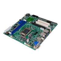
IEI Technology IMB-H110-ECO-R10 User Manual (161 pages)
microATX Motherboard Supports 6th Generation LGA1151 Intel Core i7/i5/i3, Pentium or Celeron CPU, Intel H110 Chipset, DDR4, VGA, DVI-I, LVDS, iDP, Dual GbE LAN, USB 3.0, SATA 6Gb/s, 12 COM Ports, 12 USB Ports, HD Audio and RoHS
Brand:
IEI Technology
| Category:
Motherboard
| Size: 12.98 MB
Table of Contents
Table of Contents
5
Introduction
16
Introduction
17
Figure 1-1: IMB-H110
17
Features
18
Connectors
19
Figure 1-2: Connectors
19
Dimensions
20
Figure 1-3: IMB-H110 Dimensions (MM)
20
Data Flow
21
Figure 1-4: Data Flow Diagram
21
Technical Specifications
22
Table 1-1: IMB-H110 Specifications
24
Packing List
25
Anti-Static Precautions
26
Unpacking Precautions
26
Packing List
27
Table 2-1: Packing List
27
Optional Items
28
Table 2-2: Optional Items
29
Connectors
30
Peripheral Interface Connectors
31
IMB-H110 Layout
31
Figure 3-1: Peripheral Interface Connectors
31
Peripheral Interface Connectors
32
External Interface Panel Connectors
33
Table 3-1: Peripheral Interface Connectors
33
Table 3-2: External Peripheral Connectors
33
Internal Peripheral Connectors
34
ATX Power Connector
34
Additional Power Connector
34
Figure 3-2: +12V ATX Power Connector Pinout Location
34
Table 3-3: +12V ATX Power Connector Pinouts
34
ATX Power Connector
35
Figure 3-3: Additional Power Connector Location
35
Table 3-4: Additional Power Connector Pinouts
35
Figure 3-4: ATX Power Connector Location
36
Table 3-5: ATX Power Connector Pinouts
36
Audio Connector
37
Figure 3-5: Audio Connector Location
37
Table 3-6: Audio Connector Pinouts
37
Backlight Inverter Connector
38
Figure 3-6: Backlight Inverter Connector Location
38
Table 3-7: Backlight Inverter Connector Pinouts
38
Battery Connector
39
Figure 3-7: Battery Connector Location
39
Chassis Intrusion Connector
40
DDR4 DIMM Sockets
40
Figure 3-8: Chassis Intrusion Connector Location
40
Table 3-8: Chassis Intrusion Connector Pinouts
40
Digital I/O Connector
41
Figure 3-9: DDR4 DIMM Socket Locations
41
Figure 3-10: Digital I/O Connector Location
41
EC Debug Connector
42
Figure 3-11: EC Debug Connector Location
42
Table 3-9: Digital I/O Connector Pinouts
42
Fan Connector (CPU)
43
Figure 3-12: CPU Fan Connector Location
43
Table 3-10: EC Debug Connector Pinouts
43
Fan Connector (System)
44
Figure 3-13: System Fan Connector Location
44
Table 3-11: CPU Fan Connector Pinouts
44
Table 3-12: System Fan Connector Pinouts
44
Front Panel Connector
45
Figure 3-14: Front Panel Connector Location
45
Table 3-13: Front Panel Connector Pinouts
45
I 2 C Connector
46
Figure 3-15: I 2 C Connector Location
46
Table 3-14: I 2 C Connector Pinouts
46
Internal Displayport Connector
47
Figure 3-16: Internal Displayport Connector Location
47
Keyboard and Mouse Connector
48
Figure 3-17: Keyboard and Mouse Connector Location
48
Table 3-15: Internal Displayport Connector Pinouts
48
LAN LED Connectors
49
Figure 3-18: LAN LED Connector Locations
49
Table 3-16: Keyboard and Mouse Connector Pinouts
49
LVDS Connector
50
Figure 3-19: LVDS Connector Location
50
Table 3-17: LAN LED Connector Pinouts
50
Parallel Port Connector
51
Table 3-18: LVDS Connector Pinouts
51
PCI Slots
52
Figure 3-20: Parallel Port Connector Location
52
Table 3-19: Parallel Port Connector Pinouts
52
Pcie X1 Slot
53
Figure 3-21: PCI Slot Locations
53
Figure 3-22: Pcie X1 Slot Location
53
Pcie X16 Slot
54
Pcie Mini Slot
54
Figure 3-23: Pcie X16 Slot Location
54
Figure 3-24: Pcie Mini Slot Location
55
Power Button
56
Figure 3-25: Power Button Location
56
Table 3-20: Pcie Mini Slot Pinouts
56
Serial Port Connectors
57
Figure 3-26: RS-232 Serial Port Connector Locations
57
Table 3-21: RS-232 Serial Port Connector Pinouts
57
RS-232/422/485 Serial Port Connectors
58
Figure 3-27: RS-232/422/485 Serial Port Connector Locations
58
SATA 6Gb/S Drive Connector
59
Table 3-22: RS-232/422/485 Serial Port Connector Pinouts
59
Table 3-23: DB-9 RS-232/422/485 Pinouts
59
Figure 3-28: SATA 6Gb/S Drive Connector Locations
60
Table 3-24: SATA 6Gb/S Drive Connector Pinouts
60
Smbus Connector
61
Figure 3-29: Smbus Connector Location
61
Table 3-25: Smbus Connector Pinouts
61
SPI Flash Connector
62
Figure 3-30: SPI Flash Connector Location
62
Table 3-26: SPI Flash Connector Pinouts
62
SPI Flash Connector, EC
63
Figure 3-31: SPI EC Flash Connector Location
63
Table 3-27: SPI EC Flash Connector Pinouts
63
TPM Connector
64
Figure 3-32: TPM Connector Location
64
Table 3-28: TPM Connector Pinouts
64
USB 2.0 Connector
65
Figure 3-33: USB 2.0 Connector Locations
65
Table 3-29: USB 2.0 Connector Pinouts
65
External Peripheral Interface Connector Panel
66
Audio Connector
66
Figure 3-34: External Peripheral Interface Connector
66
Ethernet and USB 3.0 Connectors
67
Figure 3-35: Audio Connector
67
Table 3-30: USB 3.0 Port Pinouts
67
USB 2.0 Connectors
68
Figure 3-36: LAN Connector
68
Table 3-31: LAN Pinouts
68
Table 3-32: USB 2.0 Port Pinouts
68
VGA and DVI-I Connectors
69
Table 3-33: DVI-I Connector Pinouts
69
Figure 3-37: DVI-I Connector
70
Figure 3-38: VGA Connector
70
Table 3-34: VGA Connector Pinouts
70
Installation
71
Anti-Static Precautions
72
Installation Considerations
72
Socket Lga1151 Cpu Installation
74
Figure 4-1: Disengage the CPU Socket Load Lever
74
Figure 4-2: Remove Protective Cover
75
Figure 4-3: Insert the Socket LGA1151 CPU
76
Figure 4-4: Close the Socket LGA1151
76
Socket Lga1151 Cooling Kit Installation
77
Figure 4-5: Cooling Kit Support Bracket
78
DIMM Installation
79
Figure 4-6: DIMM Installation
79
Full-Size Pcie Mini Card Installation
80
Figure 4-7: Removing the Retention Screw
80
Figure 4-8: Inserting the Full-Size Pcie Mini Card into the Slot at an Angle
80
Half-Size Pcie Mini Card Installation
81
Figure 4-9: Securing the Full-Size Pcie Mini Card
81
Figure 4-10: Removing the Standoff
82
Figure 4-11: Installing the Standoff
82
Figure 4-12: Inserting the Half-Size Pcie Mini Card into the Slot at an Angle
83
Figure 4-13: Securing the Half-Size Pcie Mini Card
83
System Configuration
84
AT/ATX Power Mode Setting
84
Clear CMOS Button
84
Figure 4-14: AT/ATX Power Mode Switch Location
84
Table 4-1: AT/ATX Power Mode Switch Settings
84
DVI/CRT Selection Switch
85
Figure 4-15: Clear CMOS Button Location
85
Figure 4-16: DVI/CRT Selection Switch Location
85
Table 4-2: DVI/CRT Selection Switch Settings
85
Flash Descriptor Security Override Jumper
86
Figure 4-17: Flash Descriptor Security Override Jumper Location
86
Table 4-3: Flash Descriptor Security Override Jumper Settings
86
LVDS Panel Resolution Selection Switch
87
Figure 4-18: LVDS Panel Resolution Selection Switch Location
87
Table 4-4: LVDS Panel Resolution Selection
87
LVDS Voltage Selection Jumper
88
Figure 4-19: LVDS Voltage Selection Jumper Location
88
Table 4-5: LVDS Voltage Selection Jumper Settings
88
Lvds/Idp Selection Switch
89
Figure 4-20: Lvds/Idp Selection Switch Location
89
Table 4-6: Lvds/Idp Selection Switch Settings
89
USB Power Selection
90
Internal Peripheral Device Connections
90
SATA Drive Connection
90
Table 4-7: BIOS Options and Configured USB Ports
90
Table 4-8: USB Power Source Setup
90
Figure 4-21: SATA Drive Cable Connection
91
Adding Usb 3.0 Drivers to a Windows 7 Installation Image
92
Figure 4-22: SATA Power Drive Connection
92
Figure 4-23: Windows 7 USB 3.0 Creator Utility
93
Driver Installation
94
Bios
96
Introduction
97
Starting Setup
97
Using Setup
97
Getting Help
98
Unable to Reboot after Configuration Changes
98
BIOS Menu Bar
98
Table 5-1: BIOS Navigation Keys
98
Main
99
Advanced
100
Trusted Computing
101
ACPI Settings
102
Super IO Configuration
103
Serial Port 1 ~ 6 Configuration
104
Serial Port 1 Configuration
104
Serial Port 2 Configuration
105
Serial Port 3 Configuration
106
Parallel Port Configuration
110
F81866SEC Super IO Configuration
112
Serial Port 7~12 Configuration
112
Iwdd H/W Monitor
113
Smart Fan Mode Configuration
114
RTC Wake Settings
115
Serial Port Console Redirection
117
Legacy Console Redirection Settings
120
CPU Configuration
120
SATA Configuration
122
Nvme Configuration
123
USB Configuration
124
Iei Feature
125
Chipset
126
System Agent (SA) Configuration
127
Graphics Configuration
128
PEG Port Configuration
130
Memory Configuration
131
PCH-IO Configuration
132
Table 5-2: BIOS Options and Configured USB Ports
133
PCI Express Configuration
134
HD Audio Configuration
136
Security
137
Boot
138
Save & Exit
140
A Regulatory Compliance
141
B Product Disposal
143
CBIOS Options
145
D Terminology
149
E Digital I/O Interface
153
Introduction
154
Assembly Language Sample 1
155
Assembly Language Sample 2
155
F Watchdog Timer
156
G Hazardous Materials Disclosure
159
Advertisement
Advertisement
Related Products
IEI Technology IMB-H110
IEI Technology IMB-H110-R10
IEI Technology IMB-H810-i2
IEI Technology IMB-H612
IEI Technology IMB-H610
IEI Technology IMB-H810-i2-R11
IEI Technology IMB-H810-ECO-R11
IEI Technology IMB-8550
IEI Technology IMB-9454G-R40
IEI Technology IMBA-BDE-1518
IEI Technology Categories
Motherboard
Touch Panel
Computer Hardware
Single board computers
Desktop
More IEI Technology Manuals
Login
Sign In
OR
Sign in with Facebook
Sign in with Google
Upload manual
Upload from disk
Upload from URL