Sign In
Upload
Manuals
Brands
IEI Technology Manuals
Motherboard
ICE-BT-T6
IEI Technology ICE-BT-T6 Manuals
Manuals and User Guides for IEI Technology ICE-BT-T6. We have
1
IEI Technology ICE-BT-T6 manual available for free PDF download: User Manual
IEI Technology ICE-BT-T6 User Manual (111 pages)
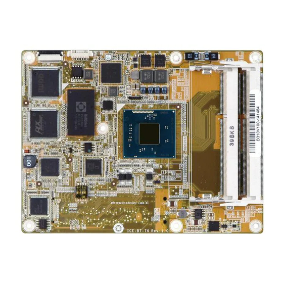
Com Express R2.1 Module (Type 6), 22nm Intel Atom or Celeron Processor 2GB DDR3, EEPROM and RoHS Compliant
Brand:
IEI Technology
| Category:
Motherboard
| Size: 3.64 MB
Table of Contents
User Manual
1
Table of Contents
4
1 Introduction
11
Introduction
12
Figure 1-1: ICE-BT-T6
12
Model Variations
13
Features
13
Table 1-1: Model Variations
13
Board Overview
14
Figure 1-2: On-Board Components and Connectors
14
Dimensions
15
Figure 1-3: ICE-BT-T6 Dimensions (MM)
15
Data Flow
16
Figure 1-4: Data Flow Diagram
16
Technical Specifications
17
Table 1-2: ICE-BT-T6 Specifications
18
2 Packing List
19
Anti-Static Precautions
20
Unpacking Precautions
20
Packing List
21
Table 2-1: Packing List
21
Optional Items
22
Table 2-2: Optional Items
22
3 Connectors
23
Peripheral Interface Connectors
24
ICE-BT-T6 Layout
24
Figure 3-1: Connectors (Front Side)
24
Figure 3-2: Connectors (Solder Side)
24
Peripheral Interface Connectors
25
Table 3-1: Peripheral Interface Connectors
25
Internal Peripheral Connectors
26
COM Express Connector AB
26
Figure 3-3: COM Express Connector AB Location
26
COM Express Connector CD
30
Figure 3-4: COM Express Connector CD Location
30
Table 3-2: COM Express Connector Pin Definitions
30
SO-DIMM Connectors
34
Table 3-3: COM Express Connector CD Pin Definitions
34
Figure 3-5: SO-DIMM Connector Locations
35
4 Installation
36
Anti-Static Precautions
37
Installation Considerations
37
So-DIMM Installation
39
Figure 4-1: SO-DIMM Installation
39
Jumper Settings
40
LVDS Panel Type Selection
40
Table 4-1: LVDS Panel Type Selection
40
Mounting Ice-Bt-T6 to Baseboard
41
Figure 4-2: LVDS Panel Type Selection Switch Location
41
Figure 4-3: Connect the COM Express Connectors
42
Figure 4-4: Secure the Heatsink
42
5 Bios
43
Introduction
44
Starting Setup
44
Using Setup
44
Getting Help
45
Unable to Reboot after Configuration Changes
45
BIOS Menu Bar
45
Table 5-1: BIOS Navigation Keys
45
Main
46
BIOS Menu 1: Main
46
Advanced
47
BIOS Menu 2: Advanced
47
ACPI Settings
48
BIOS Menu 3: ACPI Settings
48
Super IO Configuration
49
Serial Port N Configuration
49
BIOS Menu 4: IT8528 Super IO Configuration
49
BIOS Menu 5: Serial Port N Configuration Menu
49
Hardware Monitor
52
BIOS Menu 6: Hardware Monitor
52
Smart Fan Function
53
BIOS Menu 7: Smar Fan Function
53
IT8518 Super IO Configuration
54
Serial Port N Configuration
54
BIOS Menu 8: IT8518 Super IO Configuration
54
BIOS Menu 9: Serial Port N Configuration Menu
54
RTC Wake Settings
58
BIOS Menu 10: RTC Wake Settings
58
Serial Port Console Redirection
59
BIOS Menu 11: Serial Port Console Redirection
59
CPU Configuration
62
BIOS Menu 12: CPU Configuration
62
Thermal Configuration
64
BIOS Menu 13: Thermal Configuration
64
IDE Configuration
66
BIOS Menu 14: SATA Configuration
66
Trusted Computing
68
BIOS Menu 15: Trusted Computing
68
USB Configuration
69
BIOS Menu 16: USB Configuration
69
Chipset
70
BIOS Menu 17: Chipset
70
North Bridge
71
Intel IGD Configuration
71
BIOS Menu 18: North Bridge Configuration
71
BIOS Menu 19: Intel IGD Configuration
71
South Bridge Configuration
73
BIOS Menu 20: Sorth Bridge Configuration
73
Azalia HD Audio
74
BIOS Menu 21: Azalia HD Audio
74
PCI Express Configuration
75
BIOS Menu 22: PCI Express Configuration
75
Security
76
BIOS Menu 23: Security
76
Administrator Password
76
User Password
76
Boot
77
BIOS Menu 24: Boot
77
Save & Exit
79
BIOS Menu 25: Save & Exit
79
6 Software Drivers
81
Available Software Drivers
82
Starting the Driver Program
82
Figure 6-1: Start up Screen
83
Figure 6-2: Drivers
83
Chipset Driver Installation
84
Figure 6-3: Chipset Driver Welcome Screen
84
Figure 6-4: Chipset Driver License Agreement
85
Figure 6-5: Chipset Driver Read Me File
85
Figure 6-6: Chipset Driver Setup Operations
86
Figure 6-7: Chipset Driver Installation Finish Screen
86
Graphics Driver Installation
87
Figure 6-8: Graphics Driver License Agreement
88
Figure 6-9: Graphics Driver Read Me File
88
Figure 6-10: Graphics Driver Setup Operations
89
Figure 6-11: Graphics Driver Installation Finish Screen
89
Lan Driver Installation
90
Figure 6-12: Graphics Driver Installation Finish Screen
90
Figure 6-13: Windows Control Panel
91
Figure 6-14: System Control Panel
91
Figure 6-15: Device Manager List
92
Figure 6-16: Update Driver Software Window
93
Figure 6-17: Locate Driver Files
93
ABIOS Options
95
B Terminology
98
C Digital I/O Interface
102
Introduction
103
Assembly Language Sample 1
104
Assembly Language Sample 2
104
D Watchdog Timer
105
E Hazardous Materials Disclosure
108
Hazardous Materials Disclosure Table for IPB Products Certified as Rohs Compliant under 2002/95/EC Without Mercury
109
Advertisement
Advertisement
Related Products
IEI Technology ICE-945GSE
IEI Technology ICE-QM871
IEI Technology ICE-BT-T10
IEI Technology ICE-BT-T10-E38151
IEI Technology ICE-BT-T10-E38251
IEI Technology ICPMB-8650
IEI Technology ICPMB-8660
IEI Technology ICPMB-7880
IEI Technology IMBA-9454G
IEI Technology IMB-Q354
IEI Technology Categories
Motherboard
Touch Panel
Computer Hardware
Single board computers
Desktop
More IEI Technology Manuals
Login
Sign In
OR
Sign in with Facebook
Sign in with Google
Upload manual
Upload from disk
Upload from URL