Sign In
Upload
Manuals
Brands
IEI Technology Manuals
Computer Hardware
DRPC-W-TGL-U-i7C-R10
IEI Technology DRPC-W-TGL-U-i7C-R10 Manuals
Manuals and User Guides for IEI Technology DRPC-W-TGL-U-i7C-R10. We have
1
IEI Technology DRPC-W-TGL-U-i7C-R10 manual available for free PDF download: User Manual
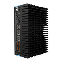
IEI Technology DRPC-W-TGL-U-i7C-R10 User Manual (155 pages)
Fanless System with Intel Tiger Lake-U Processors, Triple 2.5GbE LAN, HDMI, DP, 8GB Memory Pre-installed, 12V DC and RoHS
Brand:
IEI Technology
| Category:
Computer Hardware
| Size: 7 MB
Table of Contents
Table of Contents
5
Introduction
16
Overview
17
Figure 1-1: DRPC-W-TGL Series
17
Feature
18
Model Variations
18
Table 1-1: DRPC-W-TGL Series Model Variations
18
Technical Specifications
19
Table 1-2: Technical Specifications
19
Front Panel
20
Top Panel
20
Figure 1-2: Front Panel
20
Figure 1-3: Top Panel
20
Physical Dimensions
21
Figure 1-4: Physical Dimensions
21
Unpacking
22
Anti-Static Precautions
23
Unpacking Precautions
23
Unpacking Checklist
24
Installation
27
Installation Precautions
28
Cover Removal
29
Hard Disk Bracket Removal
29
Storage Installation
29
Figure 3-1: Remove the Cover
29
Figure 3-2: Take out the Disk Bracket
29
Inch SSD Installation
30
SSD Installation
30
Figure 3-3: HDD Installation
30
Figure 3-4: Inserting the M.2 Module into the Slot at an Angle
30
Wi-Fi Module Installation (Optional)
31
Figure 3-5: Securing the M.2 Module
31
Figure 3-6: Inserting the WLAN Module
31
Figure 3-7: Securing the WLAN Module
32
Figure 3-8: Connecting RF Cables
32
Expansion I/O Installation (Optional)
33
Serial Port Installation
33
Figure 3-9: Securing SMA Connector and External Antenna Installation
33
Figure 3-10: Connect the Serial Cable to the Serial Connector
33
GPIO Installation
34
Figure 3-11: Knock out the Reserved Holes
34
Figure 3-12: Connect the GPIO Cable to the GPIO Connector
34
Idpm Installation
35
Figure 3-13: Knock out the Reserved Holes
35
Figure 3-14:Inserting the M.2 Module into the Slot at an Angle
35
Figure 3-15: Securing the M.2 Module
36
Figure 3-16: Connect the VGA Cable to the VGA Connector
36
Figure 3-17: Knock out the Reserved Holes
36
Cover Installation
37
System Fan Installation (Optional)
37
Figure 3-18: Install the Cover
37
Mounting Brackets Installation
38
Figure 3-19: External Fan Module Installation
38
Figure 3-20: Align the Retention Screw Holes
38
Figure 3-21: Secure the Brackets
39
Figure 3-22: Mounting the System
39
External Peripheral Interface Connectors
40
HDMI/DP Connector
40
LAN Connectors
40
Figure 3-23: HDMI/DP Connection
40
Figure 3-24: LAN Connection
41
Figure 3-25: RJ-45 Ethernet Connector
41
Table 3-1: RJ-45 Ethernet Connector Leds
41
Power Connector
42
USB 3.2 Gen 2 (10Gb/S) Connectors
42
Figure 3-26: Power Connector
42
Table 3-2: Power Connector Pinouts
42
Internal Peripheral Interface Connectors (Optional)
43
Digital I/O Connector
43
Figure 3-27: USB Connection
43
Figure 3-28: Digital I/O Connector Location
43
Slot, B-Key
44
Figure 3-29: M.2 B Key Slot Location
44
Table 3-3: Digital I/O Connector Pinouts
44
Slot, A-Key
46
Figure 3-30: M.2 A-Key Slot Location
46
Table 3-4: M. 2 B Key Slot Pinouts
46
USB 2.0 Connector
48
Figure 3-31: USB Connector Location
48
Table 3-5: M.2 A-Key Slot Pinouts
48
Table 3-6: USB Connector Pinouts
48
IDPM1 Display Connector
49
Figure 3-32: Idpm Slot Location
49
Table 3-7: Idpm Connector Pinouts
50
Audio Connector
51
Figure 3-33: Audio Connector Location
51
Table 3-8: Audio Connector Pinouts
51
Powering On/Off the System
52
Figure 3-34: Power Input & Button & LED
52
Available Drivers
53
Figure 3-35:Power Button
53
Figure 3-36: IEI Resource Download Center
53
Driver Download
54
Maintenance
55
Flash Descriptor Security Override Jumper
56
Figure 3-37: ME Override Setting Jumper Locations
56
Table 3-9: ME Override Setting Jumper Pinouts
56
Clear CMOS Button
57
Figure 3-38: Clear CMOS Location
57
Table 3-10: Clear CMOS Pinouts
57
AT/ATX Power Mode Setting
58
Table 3-11: AT/ATX Power Mode Switch Pinouts
58
System Motherboard
59
Peripheral Interface Connectors
60
DRPC-W-TGL Series Layout
60
Figure 4-1: Connector and Jumper Locations
60
External Interface Panel Connectors
61
Table 4-1: Peripheral Interface Connectors
61
Table 4-2: Rear Panel Connectors
61
Internal Peripheral Connectors
62
Battery Connector
62
Figure 4-2: Battery Connector Location
63
Table 4-3: Battery Connector Pinouts
63
Digital I/O Connector
64
Figure 4-3: Digital I/O Connector Location
64
Table 4-4: Digital I/O Connector Pinouts
64
Fan Connector
65
Figure 4-4: Fan Connector Location
65
Table 4-5: Fan Connector Pinouts
65
Front Panel Connector
66
Figure 4-5: Front Panel Connector Location
66
Table 4-6: Front Panel Connector Pinouts
66
LAN LED Connectors
67
Figure 4-6: LAN LED Connector Locations
67
Table 4-7: LAN LED Connector Pinouts
67
Idpm Connector
68
Figure 4-7: Idpm Connector Location
68
Table 4-8: Idpm Connector Pinouts
69
Slot, B-Key
70
Figure 4-8: M.2 B-Key Slot Location
70
Table 4-9: M.2 B-Key Slot Pinouts
71
Slot, A-Key
72
Figure 4-9: M.2 A-Key Slot Location
72
Table 4-10: M.2 A-Key Slot Pinouts
73
DDR4 SO-DIMM Socket
74
Figure 4-10: DDR4 SO-DIMM Socket Location
74
Power Connector
75
Figure 4-11: +12V DC-IN Power Connector Location
75
Table 4-11: +12V DC-IN Power Connector Pinouts
75
Power Button Connector
76
Figure 4-12: Power Button Connector Location
76
Table 4-12: Power Button Connector Pinouts
76
Reset Button Connector
77
Figure 4-13: Reset Button Connector Location
77
Table 4-13: Reset Button Connector Pinouts
77
Serial Port Connector
78
Figure 4-14: RS-232 Serial Port Connector Location
78
Table 4-14: RS-232 Serial Port Connector Pinouts
78
RS-232/422/485 Serial Port Connector
79
Figure 4-15: RS-232/422/485 Connector Location
79
Table 4-15: RS-232/422/485 Serial Port Connector Pinouts
79
SATA 6Gb/S Drive Connector
80
Figure 4-16: SATA 6Gb/S Drive Connectors Location
80
Table 4-16: DB-9 RS-232/422/485 Pinouts
80
SATA Power Connector
81
Figure 4-17: SATA Power Connector Location
81
Table 4-17: SATA Power Connector Pinouts
81
Smbus/I C Connector
82
Figure 4-18: Smbus Connector Location
82
Table 4-18: Smbus Connector Pinouts
82
USB 2.0 Connector
83
Figure 4-19: USB Connector Location
83
Table 4-19: USB Connector Pinouts
83
External Peripheral Interface Connector Panel
84
Figure 4-20: External Peripheral Interface Connector
84
HDMI Connectors
85
Figure 4-21: HDMI Connector Pinout Locations
85
Table 4-20: HDMI Connector Pinouts
85
DP Connector
86
Figure 4-22: DP Connector Pinout Locations
86
Table 4-21: DP Connector Pinouts
86
LAN Connectors
87
Figure 4-23: LAN Connector
87
Table 4-22: LAN Pinouts
87
Table 4-23: RJ-45 Ethernet Connector Leds
87
USB 3.2 Gen 2 Connectors
88
Figure 4-24: USB 3.2 Gen 2 Port Pinouts
88
Table 4-24: USB 3.2 Gen 2 Port Pinouts
88
Driver Download
89
Available Drivers
91
Figure 4-25: IEI Resource Download Center
91
Bios
92
Introduction
93
Starting Setup
93
Figure 5-1: BIOS Starting Menu
93
Using Setup
94
Keyboard Navigation
94
Table 5-1: BIOS Navigation Keys
94
Touch Navigation
95
Figure 5-2: BIOS On-Screen Navigation Keys
95
Getting Help
96
Unable to Reboot after Configuration Changes
96
BIOS Menu Bar
96
Main
97
Advanced
100
BIOS Menu 3: Advanced
100
CPU Configuration
101
Trusted Computing
105
BIOS Menu 7: PCH-FW Configuration
105
F81216 Super IO Configuration
106
BIOS Menu 8: F81966 Super IO Configuration
106
Serial Port 1 Configuration
107
BIOS Menu 9: Serial Port 1 Configuration Menu
107
Serial Port 2 Configuration
108
BIOS Menu 10: Serial Port 2 Configuration Menu
108
Serial Port 3 Configuration
109
BIOS Menu 11: Serial Port 3 Configuration Menu
109
IT5571 H/W Monitor
111
BIOS Menu 12: IT5571 H/W Monitor
111
Smart Fan Mode Configuration
112
BIOS Menu 13: Smart Fan Mode Configuration
112
RTC Wake Settings
114
Serial Port Console Redirection
116
Console Redirection Settings
118
BIOS Menu 18: COM Console Redirection Settings
118
Nvme Configuration
121
BIOS Menu 19: Nvme Configuration
121
Chipset
122
BIOS Menu 20: Chipset
122
System Agent (SA) Configuration
123
BIOS Menu 21: System Agent (SA) Configuration
123
Memory Configuration
124
BIOS Menu 22: Memory Configuration
124
Graphics Configuration
125
BIOS Menu 23: Graphics Configuration
125
PCH-IO Configuration
127
BIOS Menu 24: PCH-IO Configuration
127
PCI Express Configuration
129
Pcie Root Port Setting
129
Figure 5-3: BIOS Options and Configured USB Ports
129
BIOS Menu 25: PCI Express Configuration
129
BIOS Menu 26: Pcie Slot Configuration Submenu
130
SATA Configuration
132
BIOS Menu 27: SATA Configuration
132
HD Audio Configuration
134
BIOS Menu 28: HD Audio Configuration
134
Security
135
BIOS Menu 29: Security
135
Boot
136
Boot Configuration
136
BIOS Menu 30: Boot
136
Boot Option Priorities
137
Save & Exit
138
A Regulatory Compliance
140
B Product Disposal
142
CBIOS Options
144
D Watchdog Timer
148
E Error Beep Code
151
Pei Beep Codes
152
Dxe Beep Codes
152
F Hazardous Materials Disclosure
153
Rohs II Directive (2015/863/EU)
154
China Rohs
155
Advertisement
Advertisement
Related Products
IEI Technology DRPC-W-TGL Series
IEI Technology DRPC-W-TGL-U-I5C-R10
IEI Technology DRPC-W-TGL-U-i3C-R10
IEI Technology DRPC-W-TGL-U-CC-R10
IEI Technology DRPC-242-ADL-P Series
IEI Technology DRPC-242-ADL-P-i3CS
IEI Technology DRPC-242-ADL-P-i5CS
IEI Technology DRPC-242-ADL-P-i7CS
IEI Technology DRPC-140-EHL Series
IEI Technology DRPC-100-CV-LED-R10
IEI Technology Categories
Motherboard
Touch Panel
Computer Hardware
Single board computers
Desktop
More IEI Technology Manuals
Login
Sign In
OR
Sign in with Facebook
Sign in with Google
Upload manual
Upload from disk
Upload from URL