Sign In
Upload
Manuals
Brands
IEI Technology Manuals
Monitor
DM-F19A/PC-R31
IEI Technology DM-F19A/PC-R31 Manuals
Manuals and User Guides for IEI Technology DM-F19A/PC-R31. We have
1
IEI Technology DM-F19A/PC-R31 manual available for free PDF download: User Manual
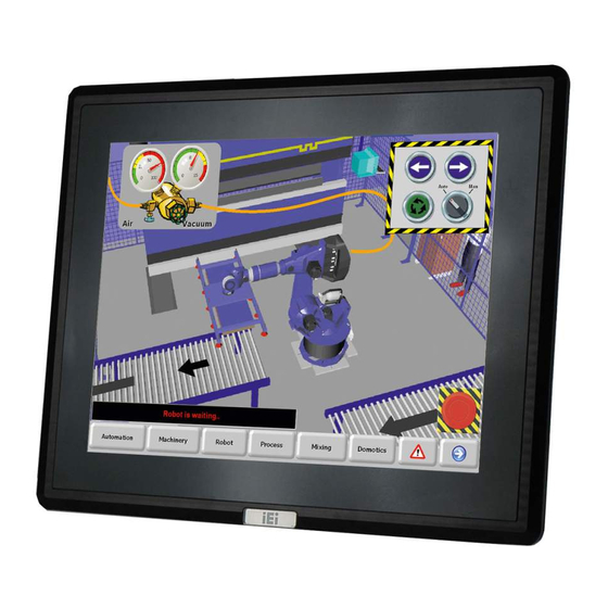
IEI Technology DM-F19A/PC-R31 User Manual (126 pages)
8" ~ 23.8" LCD Monitor DisplayPort, HDMI, VGA, IP 65 Protection, RoHS
Brand:
IEI Technology
| Category:
Monitor
| Size: 15 MB
Table of Contents
Table of Contents
7
1 Introduction
15
Overview
16
Features
16
Figure 1-1: DM-F Series
16
Model Variations
17
Applications
17
Table 1-1: DM-F Series Model Variations
17
Front View
18
Figure 1-2: Typical Monitor Front View
18
Rear View
19
Figure 1-3: DM-F08A Rear View
19
Figure 1-4: DM-F12A/15A/W15A/17A/19A/W19A/22A/24A Rear View
19
Connectors
20
DM-F08A Connectors
20
Figure 1-5: Bottom Panel Connectors (DM-F08A)
20
Figure 1-6: Side Panel Connectors (DM-F08A)
20
DM-F12A ~ DM-F19A Connectors
21
DM-F22A and DM-F24A Connectors
21
Figure 1-7: Bottom Panel Connectors (DM-F12A/15A/W15A/17A/19A/W19A)
21
Figure 1-8: Side Panel Connector (DM-F12A/15A/17A/19A)
21
Figure 1-9: Bottom Panel Connectors (DM-F22A/24A)
21
Technical Specifications
22
DM-F08A ~ DM-F(W)15A Specifications
22
Table 1-2: DM-F08A ~ DM-F(W)15A Specifications
23
DM-F17A ~ DM-F24A Specifications
24
Table 1-3: DM-F17A ~ DM-F24A Specifications
25
Physical Dimensions
26
DM-F08A Physical Dimensions
26
Figure 1-10: DM-F08A Physical Dimensions (Unit: MM)
26
DM-F12A Physical Dimensions
27
Figure 1-11: DM-F12A Physical Dimensions (Unit: MM)
27
DM-F15A Physical Dimensions
28
Figure 1-12: DM-F15A Physical Dimensions (Unit: MM)
28
DM-Fw15A Physical Dimensions
29
Figure 1-13: DM-FW15A Physical Dimensions (Unit: MM)
29
DM-F17A Physical Dimensions
30
Figure 1-14: DM-F17A Physical Dimensions (Unit: MM)
30
DM-F19A Physical Dimensions
31
Figure 1-15: DM-F19A Physical Dimensions (Unit: MM)
31
DM-Fw19A Physical Dimensions
32
Figure 1-16: DM-FW19A Physical Dimensions (Unit: MM)
32
DM-F22A Physical Dimensions
33
Figure 1-17: DM-F22A Physical Dimensions (Unit: MM)
33
DM-F24A Physical Dimensions
34
Figure 1-18: DM-F24A Physical Dimensions (Unit: MM)
34
2 Unpacking
35
Unpacking Procedure
36
Packing List
37
Table 2-1: Packing List
37
Optional Items
38
3 Installation
39
Installation Precautions
40
External Peripheral Device Connection
41
DC-In Jack
41
36 V Terminal Block (Optional)
41
Figure 3-1: DC Jack
41
Figure 3-2: 3-Pin Terminal Block
41
Usb for Touch Panel Connector
42
Vga Connector
42
Figure 3-3: USB Touch Panel Connector
42
Figure 3-4: VGA Connector
42
Table 3-1: USB Touch Panel Connector Pinouts
42
Table 3-2: VGA Connector Pinouts
42
DVI-D Connector (F08A and F19A Only)
43
Figure 3-5: DVI-D Connector
43
Table 3-3: DVI-D Connector Pinouts
43
Displayport Connector (F12A ~ F24A Only)
44
Figure 3-6: Displayport Connector
44
Table 3-4: Displayport Connector Pinouts
44
HDMI Connector (F12A, F(W)15A, F17A, FW19A, F22A, F24A Only)
45
Port for Touch Panel (Reserved for Resistive Touch)
45
Figure 3-7: HDMI Connector
45
Table 3-5: HDMI Connector Pinouts
45
Table 3-6: RS-232 Touch Panel Connector Pinouts
45
Installing RS-232 Connector
46
Figure 3-8: RS-232 Touch Panel Connector
46
Figure 3-9: Rear Panel Retention Screw Removal (DM-F08A)
46
Figure 3-10: Rear Panel Retention Screw Removal (DM-F12A ~ DM-F24A)
47
Figure 3-11: Connecting RS-232 Cable
47
Mounting the Monitor
48
Figure 3-12: Hex Jack Screws for Securing RS-232 Connector
48
Panel Mounting
48
Figure 3-13: Mounting Clamps Holder
49
Figure 3-14: Mounting Clamps
49
Table 3-7: Panel Mounting Clamps
49
Figure 3-15: DM-F08A Cutout Dimensions (Unit: MM)
50
Figure 3-16: DM-F12A Cutout Dimensions (Unit: MM)
50
Figure 3-17: DM-F15A Cutout Dimensions (Unit: MM)
50
Figure 3-18: DM-FW15A Cutout Dimensions (Unit: MM)
51
Figure 3-19: DM-F17A Cutout Dimensions (Unit: MM)
51
Figure 3-20: DM-F19A Cutout Dimensions (Unit: MM)
51
Figure 3-21: DM-FW19A Cutout Dimensions (Unit: MM)
52
Figure 3-22: DM-F22A Cutout Dimensions (Unit: MM)
52
Figure 3-23: DM-F24A Cutout Dimensions (Unit: MM)
52
Figure 3-24: Secure the Mounting Clamp Holders
53
Figure 3-25: Slide into the Panel
54
Figure 3-26: Panel Mounting Clamp Installation
54
Figure 3-27: Mounting Clamps Holder Dimensions
55
Figure 3-28: Ultra Set Plate Dimensions
55
Cabinet and Rack Installation (for F08A ~ F17A & FW19A)
56
Figure 3-29: Bolt Dimensions
56
Figure 3-30: Steering Button Dimensions
56
Figure 3-31: Secure the Mounting Clamp Holders
57
Figure 3-32: Slide into the Rack/Cabinet Bracket
58
Figure 3-33: Secure the Rack/Cabinet Bracket
58
Cabinet and Rack Installation (for F19A)
59
Figure 3-34: Install into a Rack/Cabinet
59
Figure 3-35: Slide DM-F19A into the Rack/Cabinet Bracket
60
Figure 3-36: Secure the Mounting Brackets
60
Figure 3-37: Install DM-F19A into a Rack/Cabinet
61
Wall Mounting
61
Figure 3-38: Attach Wall Mounting Kit to the Wall
62
Figure 3-39: Hook Onto Wall Mounting Kit
63
Figure 3-40: Tighten Retention Screw
63
Figure 3-41: VESA Mounting Holes (DM-F08A)
64
Figure 3-42: VESA Mounting Holes (DM-F12A ~ DM-F24A)
64
Stand Installation
64
Arm Installation
65
Figure 3-43: Monitor Stand Mounting
65
Figure 3-44: Monitor Arm Mounting
66
4 On-Screen-Display (Osd) Controls
67
Osd Keypad
68
Figure 4-1: OSD Keypad for DM-F08A
68
Table 4-1: OSD Control Buttons for DM-F08A
68
Figure 4-2: OSD Keypad for DM-F12A ~ DM-F24A
69
Table 4-2: OSD Control Buttons for DM-F12A ~ DM-F24A
69
Osd Menu Structure
70
Table 4-3: OSD Menu Structure
70
Using the Osd
71
Picture Menu
71
Figure 4-3: Picture Menu
71
Display Menu
72
Figure 4-4: Display Menu
72
Color Setting
73
Figure 4-5: Color Menu
73
Input Menu
74
Figure 4-6: Input Menu
74
Other Menu
75
Figure 4-7: Other Menu
75
Information Menu
76
Figure 4-8: Information Menu
76
5 Software Drivers
77
Introduction
78
Or Usb Touchscreen
78
Touch Panel Driver Installation
79
Figure 5-1: Welcome Screen
81
Figure 5-2: License Agreement
82
Figure 5-3: Initiate Install
82
Figure 5-4: Installation Starts
83
Figure 5-5: Finish Installation
83
Change the Touchscreen Interface
84
Calibrating Thet
84
Ouchscreen
84
Figure 5-6: Penmount Monitor Icon
84
Figure 5-7: Penmount Monitor Popup Menu
84
Figure 5-8: Configuration Screen
85
Figure 5-9: Calibration Initiation Screen
86
Figure 5-10: Calibration Screen
86
6 Ad Boards
87
Ad Board Overview
88
Av-2525 Ad Board
88
Figure 6-1: AV-2525 AD Board Layout Diagram
88
Av-2525 Peripheral
89
Backlight Inverter
89
Lvds Connector
89
Table 6-1: Peripheral Interface Connectors (AV-2525)
89
Table 6-2: Preconfigured Jumpers (AV-2525)
89
(Lvds1)
90
Interface Connectors Connector (Inverter1)
90
Table 6-3: Backlight Inverter Connector (INVERTER1) Pinouts
90
Table 6-4: LVDS Connector (LVDS1) Pinouts
90
Connector for
91
(Cn14)
91
(Cn9)
91
Table 6-5: OSD Keypad Connector (CN14) Pinouts
91
Table 6-6: Power Input Connector (CN9) Pinouts
91
Table 6-7: RS-232 Connector for Touchscreen (RS232_1) Pinouts
91
Osd Keypad Connector
91
Power Input Connector
91
Resistive Touchscreen
92
Touchscreen
92
Touchscreen (Usb_Touch1)
92
Connector (J1)
92
Table 6-8: USB Connector for Touchscreen (USB_TOUCH1) Pinouts
92
Table 6-9: Resistive Touchscreen Connector (J1) Pinouts
92
Av-25251 Ad Board
93
Av-25251 Peripheral
93
Backlight Inverter
93
Lvds Connector
93
Figure 6-2: AV-25251 AD Board Layout Diagram
93
Table 6-10: Peripheral Interface Connectors (AV-25251)
94
Table 6-11: Preconfigured Jumpers (AV-25251)
94
(Lvds1)
95
Interface Connectors Connector (Inverter1)
95
Table 6-12: Backlight Inverter Connector (INVERTER1) Pinouts
95
Table 6-13: LVDS Connector (LVDS1) Pinouts
95
Osd Keypad Connector
96
Power Input Connector
96
Connector for
96
(Keypad1)
96
(Pwr2)
96
Table 6-14: OSD Keypad Connector (KEYPAD1) Pinouts
96
Table 6-15: Power Input Connector (PWR2) Pinouts
96
Table 6-16: RS-232 Connector for Touchscreen (RS232_1) Pinouts
96
Vga Connector
97
Touchscreen Touchscreen (Usb_Touch1)
97
Onnector (J1)
97
(Vga2)
97
Table 6-17: USB Connector for Touchscreen (USB_TOUCH1) Pinouts
97
Advertisement
Advertisement
Related Products
IEI Technology DM-F19A/R-R10
IEI Technology DM-F19A/PC-R10
IEI Technology DM-F19A/R-RS232
IEI Technology DM-F19A/PC-R20
IEI Technology DM-F19A/R-R20
IEI Technology DM-F19A/PC-R30
IEI Technology DM-F19A
IEI Technology DM-F19A/R
IEI Technology DM-F19A/PC
IEI Technology DM-F19A/R-R31
IEI Technology Categories
Motherboard
Touch Panel
Computer Hardware
Single board computers
Desktop
More IEI Technology Manuals
Login
Sign In
OR
Sign in with Facebook
Sign in with Google
Upload manual
Upload from disk
Upload from URL