Sign In
Upload
Manuals
Brands
IEI Technology Manuals
Industrial PC
AFL3-W19A-AL
IEI Technology AFL3-W19A-AL Manuals
Manuals and User Guides for IEI Technology AFL3-W19A-AL. We have
1
IEI Technology AFL3-W19A-AL manual available for free PDF download: User Manual
IEI Technology AFL3-W19A-AL User Manual (135 pages)
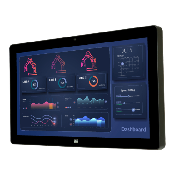
Flat Bezel Panel PC
Brand:
IEI Technology
| Category:
Industrial PC
| Size: 3 MB
Table of Contents
Table of Contents
7
1 Introduction
17
Overview
18
Figure 1-1: AFL3-W19A-AL Flat Bezel Panel PC
18
Features
19
Front Panel
20
Figure 1-2: Front View
20
Bottom Panel
21
Rear Panel
21
Figure 1-3: Bottom Panel
21
Figure 1-4: Rear View
21
Side Panel
22
Table 1-1: Supported E-Window Modules
22
System Specifications
23
Figure 1-5: Side View
22
Table 1-2: System Specifications
25
Dimensions
26
Figure 1-6: Dimensions (MM)
26
2 Unpacking
27
Unpacking
28
Packing List
28
Optional Items
30
3 Installation
32
Anti-Static Precautions
33
Installation Precautions
33
Installation and Configuration Steps
34
Removing the Back Covers
34
Figure 3-1: Back Cover Retention Screws
34
Msata Module Installation
35
Figure 3-2: Aluminum Cover Retention Screws
35
Figure 3-3: Msata Module Slot Location
36
Figure 3-4: Installing an Msata Module
36
Pcie Mini Slot Mode Selection
37
Table 3-1: Pcie Mini Slot Mode Selection (J_SATA1)
37
Hdd Installation
38
Figure 3-5: Securing the Msata Module
37
Figure 3-6: Pcie Mini Slot Mode Switch Location
37
Figure 3-7: HDD Bracket Retention Screws
38
Figure 3-8: HDD Retention Screws
39
Figure 3-9: HDD Installation
39
Figure 3-10: HDD Thermal Pad
40
Figure 3-11: Attach HDD Thermal Pad
40
Serial Port Configuration and Connection
41
Serial Port Connection
41
Figure 3-12: Serial Device Connection
41
RS-232/422/485 Serial Port Pinouts
42
Serial Port Pinouts
42
Table 3-2: RS-232 RJ-45 Serial Port (COM2) Pinouts
42
Table 3-3: RS-232 DB-9 Serial Port (COM2) Pinouts
42
Table 3-4: RS-232/422/485 RJ-45 Serial Port (COM1) Pinouts
42
Serial Port Pin 9 Selection
43
Table 3-5: RS-232/422/485 DB-9 Serial Port (COM1) Pinouts
43
Table 3-6: COM1 Pin 9 Setting Jumper Settings (JP1)
43
Table 3-7: COM2 Pin 9 Setting Jumper Settings (JP2)
43
At/Atx Mode Selection
44
AT Power Mode
44
Figure 3-13: DB-9 Serial Port Pin 9 Setting Jumper Locations
44
Figure 3-14: AT/ATX Switch Location
44
ATX Power Mode
45
Mounting the System
45
Wall Mounting
45
Figure 3-15: Wall-Mounting Bracket
46
Figure 3-16: Chassis Support Screws
47
Figure 3-17: Secure the Panel PC
48
Panel Mounting
48
Figure 3-18: Cutout Dimensions
49
Figure 3-19: Panel Mounting Kit Installation
50
Arm Mounting
51
Figure 3-20: Securing Panel Mounting Brackets
51
Figure 3-21: Arm Mounting Retention Screw Holes
52
Figure 3-22: Arm Mounting
53
Stand Mounting
53
Figure 3-23: Stand Mounting (Stand-A/Bxx)
54
Powering on the System
54
Figure 3-24: Powering on the System
55
Figure 3-25: Reset Button Location
55
Reset the System
55
Clear Cmos
56
Figure 3-26: Clear CMOS Button Location
56
Figure 3-27: IEI Resource Download Center
56
Driver Download
57
Software Installation
56
4 Bios Setup
59
Introduction
60
Starting Setup
60
Using Setup
60
BIOS Menu Bar
61
Getting Help
61
Unable to Reboot after Configuration Changes
61
Main
62
BIOS Menu 1: Main
62
System Date [XX/XX/XX]
62
System Time [XX:XX:XX]
62
Advanced
63
BIOS Menu 2: Advanced
63
ACPI Settings
64
BIOS Menu 3: ACPI Settings
64
ACPI Sleep State [S3 (Suspend to RAM)]
64
F81866 Super IO Configuration
65
Serial Port N Configuration
65
BIOS Menu 4: F81866 Super IO Configuration
65
BIOS Menu 5: Serial Port N Configuration
65
Serial Port 1 Configuration
66
Serial Port [Enabled]
66
Change Settings [Io=3F8H; IRQ=4]
66
Transfer Mode [RS232]
66
Serial Port 2 Configuration
67
Serial Port [Enabled]
67
Change Settings [Io=2F8H; IRQ=11]
67
Iwdd H/W Monitor
68
BIOS Menu 6: Iwdd H/W Monitor
68
PC Health Status
68
USB Configuration
69
BIOS Menu 7: USB Configuration
69
USB Devices
69
Legacy USB Support [Enabled]
69
CPU Configuration
70
BIOS Menu 8: CPU Configuration
70
EIST [Enabled]
70
C-States [Disabled]
71
Intel Virtualization Technology [Disabled]
71
VT-D [Disabled]
71
RTC Wake Settings
72
BIOS Menu 9: RTC Wake Settings
72
Wake System with Fixed Time [Disabled]
72
Power Saving Configuration
73
BIOS Menu 10: Power Saving Configuration
73
Power Saving Function(ERP) [Disabled]
73
Serial Port Console Redirection
74
BIOS Menu 11: Serial Port Console Redirection
74
Console Redirection [Disabled]
74
Legacy Console Redirection Settings
75
BIOS Menu 12: Legacy Console Redirection Settings
75
Legacy Serial Redirection Port [COM1]
75
IEI Feature
76
BIOS Menu 13: IEI Feature
76
Auto Recovery Function [Disabled]
76
Chipset
77
BIOS Menu 14: Chipset
77
North Bridge Configuration
78
Intel IGD Configuration
78
BIOS Menu 15: North Bridge Configuration
78
Memory Information
78
BIOS Menu 16: Intel IGD Configuration
79
Primary Display [IGD]
79
Integrated Graphics Device [Enable]
79
DVMT Pre-Allocated [256MB]
79
DVMT Total Gfx Mem [MAX]
80
LCD Control
81
BIOS Menu 17: LCD Control
81
Primary IGFX Boot Display [Auto]
81
Backlight Control Mode [LED]
81
South Bridge Configuration
82
BIOS Menu 18: South Bridge Configuration
82
Backlight Control Voltage Level [3.3V]
82
Backlight Control Type [PWM]
82
HD-Audio Configuration
83
BIOS Menu 19: HD-Audio Configuration
83
Restore on AC Power Loss [Last State]
83
USB Power SW1 [+5V DUAL]
83
PCI Express Configuration
84
BIOS Menu 20: PCI Express Configuration
84
HD-Audio Support [Enable]
84
M2_Akey1
85
M2_AKEY1 [Enabled]
85
Pcie Speed [Auto]
85
Msata1
86
BIOS Menu 22: MSATA1
86
MSATA1 [Enabled]
86
Pcie Speed [Auto]
86
SATA Configuration
87
BIOS Menu 23: SATA Configuration
87
STAT Controller [Enable]
87
SATA Mode Selection [AHCI]
87
Security
88
BIOS Menu 24: Security
88
Administrator Password
88
User Password
88
Boot
89
BIOS Menu 25: Boot
89
Bootup Numlock State [On]
89
Quiet Boot [Enabled]
90
Launch PXE Oprom [Disabled]
90
Option ROM Messages [Force BIOS]
90
UEFI Boot [Disabled]
90
Boot Option Priority
90
Save & Exit
91
BIOS Menu 26: Save & Exit
91
Save Changes and Reset
91
Discard Changes and Reset
91
Restore Defaults
91
Save as User Defaults
92
Restore User Defaults
92
5 System Maintenance
93
System Maintenance Introduction
94
Anti-Static Precautions
94
Turn off the Power
95
So-DIMM Module Replacement
95
Figure 5-1: SO-DIMM Module Location
95
Figure 5-2: SO-DIMM Installation
96
6 Interface Connectors
97
Peripheral Interface Connectors
98
Figure 6-1: Main Board Layout Diagrams
98
Internal Peripheral Connectors
99
Table 6-1: Peripheral Interface Connectors
99
Battery Connector (BAT1)
100
Chassis Intrusion Connector (CHASSIS1)
100
Debug Connector (80PORT1)
100
Table 6-2: Battery Connector (BAT1) Pinouts
100
Table 6-3: Chassis Intrusion Connector (CHASSIS1) Pinouts
100
Table 6-4: Debug Connector (80PORT1) Pinouts
100
Debug Connector, EC (CN2)
101
Digital I/O Connector (DIO1)
101
Table 6-5: EC Debug Connector (CN2) Pinouts
101
Table 6-6: Digital I/O Connector (DIO1) Pinouts
101
Inverter Connector (INV_CN1)
102
LAN1 Link LED Connector (LED_LAN1)
102
LAN2 Link LED Connector (LED_LAN2)
102
Table 6-7: Inverter Connector (INV_CN1) Pinouts
102
Table 6-8: LAN1 Link LED Connector (LED_LAN1) Pinouts
102
Table 6-9: LAN2 Link LED Connector (LED_LAN2) Pinouts
102
LVDS Connector (LVDS1)
103
Table 6-10: LVDS Connector (LVDS1) Pinouts
103
A-Key Slot (M2_AKEY1)
104
Microphone Connector (DMIC1)
105
Pcie Mini Connector, Full-Size (MSATA1)
105
Table 6-11: M.2 M-Key Slot (M2_AKEY1) Pinouts
105
Table 6-12: Microphone Connector (DMIC1) Pinouts
105
Power LED Connector (PW_LED1)
106
Table 6-13: Pcie Mini Connector (MSATA1) Pinouts
106
Table 6-14: Power LED Connector (PW_LED1) Pinouts
106
SATA Connector (SATA1)
107
Speaker Connector (SPEAKER1)
107
SPI Flash Connector (JSPI1)
107
Table 6-15: SATA Connector (SATA1) Pinouts
107
Table 6-16: Speaker Connector (SPEAKER1) Pinouts
107
Table 6-17: SPI Flash Connector (JSPI1) Pinouts
107
SPI Flash Connector, EC (JSPI2)
108
Touch Panel Connector (TOUCH1)
108
Table 6-18: SPI Flash Connector, EC (JSPI2) Pinouts
108
Table 6-19: Touch Panel Connector (TOUCH1) Pinouts
108
TTL Serial Connector, COM4 (NFC_CN1)
109
USB 2.0 Connector (USB1~USB4)
109
USB Power Connector (USB_PWR1)
109
Table 6-20: TTL Serial Connector, COM4 (NFC_CN1) Pinouts
109
Table 6-21: USB 2.0 Connector (USB1~USB4) Pinouts
109
Table 6-22: USB Power Connector (USB_PWR1) Pinouts
109
External Interface Panel Connectors
110
Ethernet Connectors (LAN1 & LAN2)
110
Table 6-23: Rear Panel Connectors
110
Table 6-24: Ethernet Connectors (LAN2 & LAN3) Pinouts
110
HDMI Connector (HDMI1)
111
RJ-45 Serial Port (COM2)
111
RS-232/422/485 DB-9 Serial Port (COM1)
111
Table 6-25: HDMI Connector (HDMI1) Pinouts
111
Table 6-26: RS-232/422/485 DB-9 Serial Port (COM1) Pinouts
111
Table 6-27: RS-232 RJ-45 Serial Port (COM2) Pinouts
111
Preconfigured Jumper Settings
112
Table 6-28: USB 3.0 Connectors (USB3-1) Pinouts
112
Table 6-29: Preconfigured Jumpers
112
Backlight Voltage Selection Jumper (J_BKPWR1)
113
Flash Descriptor Security Override Jumper
113
Table 6-30: Backlight Voltage Selection Jumper (J_BKPWR1) Settings
113
Table 6-31: Flash Descriptor Security Override Jumper Settings
113
LVDS Panel Voltage Selection Jumper (J_VLVDS1)
114
LVDS Panel Resolution Selection Jumper (SW1)
114
Table 6-32: LVDS Voltage Selection Jumper (J_VLVDS1) Settings
114
Table 6-33: LVDS Resolution Selection Jumper (SW1) Settings
114
USB 3.0 Connectors (USB3-1)
112
A Regulatory Compliance
115
B Safety Precautions
121
Safety Precautions
122
General Safety Precautions
122
Anti-Static Precautions
123
Product Disposal
124
Maintenance and Cleaning Precautions
125
Cleaning Tools
125
Maintenance and Cleaning
125
CBIOS Menu Options
127
Appendix
128
D Watchdog Timer
130
E Hazardous Materials Disclosure
133
Advertisement
Advertisement
Related Products
IEI Technology AFL3-W15C-ADLP
IEI Technology AFL3-W19C-ADLP
IEI Technology AFL3-W15C-ADLP-i3/8G-R10
IEI Technology AFL3-W15C-ADLP-i5/8G-R10
IEI Technology AFL3-W15C-ADLP-i7/8G-R10
IEI Technology AFL3-W19C-ADLP-i3/8G-R10
IEI Technology AFL3-W19C-ADLP-i5/8G-R10
IEI Technology AFL3-W19C-ADLP-i7/8G-R10
IEI Technology AFL3-W22C-ADLP-i3/8G-R10
IEI Technology AFL3-W22C-ADLP-i5/8G-R10
IEI Technology Categories
Motherboard
Touch Panel
Computer Hardware
Single board computers
Desktop
More IEI Technology Manuals
Login
Sign In
OR
Sign in with Facebook
Sign in with Google
Upload manual
Upload from disk
Upload from URL