Sign In
Upload
Manuals
Brands
IEI Technology Manuals
Touch Panel
AFL-057A-Z510
IEI Technology AFL-057A-Z510 Manuals
Manuals and User Guides for IEI Technology AFL-057A-Z510. We have
1
IEI Technology AFL-057A-Z510 manual available for free PDF download: User Manual
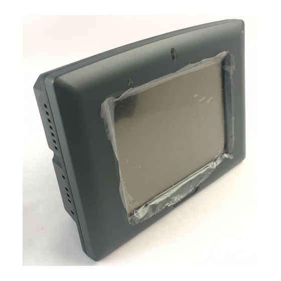
IEI Technology AFL-057A-Z510 User Manual (122 pages)
5,7" PoE Panel PC with Touch Screen Intel Atom Z510/Z530 CPU, Gigabit Ethernet, USB, RS-232/422/485, RoHS Compliant, IP 64 Protection
Brand:
IEI Technology
| Category:
Touch Panel
| Size: 6 MB
Table of Contents
Table of Contents
4
1 Introduction
12
Overview
13
Model Variations
13
Figure 1-1: AFL-057A-Z510/Z530
13
Table 1-1: Model Variations
13
Standard Features
14
External Overview
14
General Description
14
Front Panel
15
Rear Panel
15
Figure 1-2: Front View
15
Figure 1-3: Rear View
15
Top Panel and Side Panels
16
Bottom Panel
16
Figure 1-4: Top View
16
Figure 1-5: Side View
16
Internal Overview
17
Specifications
17
Figure 1-6: AFL-057A-Z510/Z530 Bottom View
17
Table 1-2: AFL-057A-Z510/Z530 System Specifications
18
Dimensions
19
Figure 1-7: Dimensions (Units in MM)
19
2 Packing List
20
Anti-Static Precautions
21
Unpacking Precautions
21
Packing List
22
3 Installation
25
Installation Precautions
26
Installation and Configuration Steps
26
Cf Card Installation
26
Figure 3-1: Back Cover Retention Screws
27
Figure 3-2: CF Card Location
27
Jumper Settings
28
Access the Switches
28
COM1 RS-232/422/485 Serial Port Select
28
Table 3-1: COM1 Mode Settings (SW1+SW4)
28
Table 3-2: COM1 Mode Settings (SW2)
28
Figure 3-3: COM1 RS-232/422/485 Serial Port Select Switch Locations
29
Table 3-3: COM1 Mode Settings (SW3)
29
COM1 RS-422 and RS-485 Pinouts
30
Mounting the System
30
Table 3-4: RS-422 Pinouts
30
Table 3-5: RS-485 Pinouts
30
Figure 3-4: Wall-Mounting Bracket
31
Wall Mounting
31
Figure 3-5: Chassis Support Screws
32
Figure 3-6: Secure the Panel PC
33
Panel Mounting
33
Figure 3-7: Panel Opening
34
Arm/Stand Mounting
35
Figure 3-8: Tighten the Panel Mounting Clamp Screws
35
Bottom Panel Connectors
36
LAN Connection (Poe Supported)
36
Figure 3-9: Arm/Stand Mounting Retention Screw Holes
36
Figure 3-10: LAN Connection
37
Gbe LAN Connector Pinouts
37
Serial Device Connection
38
Figure 3-11: Serial Device Connector
38
Table 3-6: Ethernet Connector Pinouts
38
USB Device Connection
39
Figure 3-12: USB Device Connection
39
Power -O N Procedure
40
Installation Checklist
40
Power-On Procedure (Poe)
40
Figure 3-13: RJ-45 Connector with Poe Support
41
Figure 3-14: IPS-2042TX Ethernet Switch
41
Power-On Procedure (Optional Power Adapter)
42
Figure 3-15: Power LED
42
Figure 3-16: Power Connector
42
Software Installation
43
Figure 3-17: Power LED
43
Figure 3-18: Introduction Screen
44
Figure 3-19: Available Drivers
45
4 System Maintenance
46
System Maintenance Introduction
47
Motherboard Replacement
47
Memory Module Replacement
47
Figure 4-1: Motherboard Retention Screws
48
Figure 4-2: DDR2 SO-DIMM Module Installation
49
5 Bios
50
Introduction
51
Starting Setup
51
Using Setup
51
Getting Help
52
Unable to Reboot after Configuration Changes
52
BIOS Menu Bar
52
Table 5-1: BIOS Navigation Keys
52
Main
53
BIOS Menu 1: Main
53
Advanced
54
CPU Configuration
55
BIOS Menu 2: Advanced
55
BIOS Menu 3: CPU Configuration
55
IDE Configuration
56
BIOS Menu 4: IDE Configuration
56
BIOS Menu 5: IDE Master and IDE Slave Configuration
57
IDE Master, IDE Slave
57
Super IO Configuration
61
BIOS Menu 6: Super IO Configuration
61
Remote Access Configuration
62
BIOS Menu 7: Remote Access Configuration
62
USB Configuration
63
BIOS Menu 8: USB Configuration
63
Pci/Pnp
64
BIOS Menu 9: Pci/Pnp Configuration
65
Boot
67
Boot Settings Configuration
67
BIOS Menu 10: Boot
67
BIOS Menu 11: Boot Settings Configuration
67
Security
69
BIOS Menu 12: Security
69
Chipset
70
Northbridge Configuration
71
BIOS Menu 13: Chipset
71
BIOS Menu 14:Northbridge Chipset Configuration
71
Southbridge Configuration
73
BIOS Menu 15:Southbridge Chipset Configuration
73
Exit
74
BIOS Menu 16:Exit
74
A Safety Precautions
76
Safety Precautions
77
General Safety Precautions
77
A.1 S Afety P Recautions
77
Anti-Static Precautions
78
Product Disposal
79
Maintenance and Cleaning Precautions
79
Maintenance and Cleaning
79
Cleaning Tools
80
BBIOS Options
81
C One Key Recovery
84
One Key Recovery Introduction
85
C.1 O Ne K Ey R Ecovery I Ntroduction
85
Figure C-1: IEI One Key Recovery Tool Menu
85
System Requirement
86
Supported Operating System
87
Setup Procedure for Windows
88
Hardware and BIOS Setup
88
C.2 S Etup P Rocedure for W Indows
88
Create Partitions
89
Figure C-2: Launching the Recovery Tool
89
Figure C-3: Recovery Tool Setup Menu
90
Figure C-4: Command Mode
90
Figure C-5: Partition Creation Commands
91
Install Operating System, Drivers and Applications
92
Build-Up Recovery Partition
93
Figure C-6: Launching the Recovery Tool
93
Figure C-7: System Configuration for Windows
93
Figure C-8: Build-Up Recovery Partition
94
Figure C-9: Press any Key to Continue
94
Create Factory Default Image
95
Figure C-10: Press F3 to Boot into Recovery Mode
95
Figure C-11: Recovery Tool Menu
95
Figure C-12: about Symantec Ghost Window
96
Figure C-13: Symantec Ghost Path
96
Figure C-14: Select a Local Source Drive
97
Figure C-15: Select a Source Partition from Basic Drive
97
Figure C-16: File Name to Copy Image to
98
Figure C-17: Compress Image
98
Figure C-18: Image Creation Confirmation
99
Figure C-19: Image Creation Process
99
Figure C-20: Image Creation Complete
99
Setup Procedure for Linux
100
Figure C-21: Press any Key to Continue
100
C.3 S Etup P Rocedure for L Inux
100
Figure C-22: Partitions for Linux
101
Figure C-23: System Configuration for Linux
102
Figure C-24: Access Menu.lst in Linux (Text Mode)
102
Recovery Tool Functions
103
C.4 R Ecovery T Ool F Unctions
103
Figure C-25: Recovery Tool Menu
103
Figure C-26: Recovery Tool Main Menu
104
Factory Restore
105
Figure C-27: Restore Factory Default
105
Figure C-28: Recovery Complete Window
105
Backup System
106
Figure C-29: Backup System
106
Figure C-30: System Backup Complete Window
106
Figure C-31: Restore Backup
107
Figure C-32: Restore System Backup Complete Window
107
Restore Your Last Backup
107
Figure C-33: Symantec Ghost Window
108
Manual
108
Other Information
109
Using AHCI Mode or Ali M5283 / VIA VT6421A Controller
109
C.5 O Ther I Nformation
109
System Memory Requirement
111
D Terminology
112
Watchdog Timer
116
Advertisement
Advertisement
Related Products
IEI Technology AFL-057A-LX
IEI Technology AFL-056A-LX
IEI Technology AFL-057A-Z530
IEI Technology AFL-07A-ATOM-N270/WT-R/1GB
IEI Technology AFL-08AH-ATOM-N270/WT-R/1GB
IEI Technology AFL-07A-N270/R/1G-R22
IEI Technology AFL-08AH-N270/R/1G-R22
IEI Technology AFL-07A-N270/R/1G-R21
IEI Technology AFL-08AH-N270/R/1G-R21
IEI Technology AFL-HM55
IEI Technology Categories
Motherboard
Touch Panel
Computer Hardware
Single board computers
Desktop
More IEI Technology Manuals
Login
Sign In
OR
Sign in with Facebook
Sign in with Google
Upload manual
Upload from disk
Upload from URL