Sign In
Upload
Manuals
Brands
I+ME ACTIA Manuals
Control Systems
BMS Master 4.5
I+ME ACTIA BMS Master 4.5 Manuals
Manuals and User Guides for I+ME ACTIA BMS Master 4.5. We have
1
I+ME ACTIA BMS Master 4.5 manual available for free PDF download: Hardware Manual
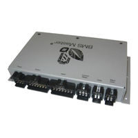
I+ME ACTIA BMS Master 4.5 Hardware Manual (76 pages)
Brand:
I+ME ACTIA
| Category:
Control Systems
| Size: 2 MB
Table of Contents
Table of Contents
3
1 Introduction
6
Components
6
Determined Use, Connection and Installation
6
Warranty and Responsibility
6
Checking, Transport and Storage
7
Remarks
7
Symbols und Writings
8
Glossary
8
2 General System Description
9
Diagram „System Components
9
Scheme „MASTER
10
Schematic for Slave C, Slave 5
11
Schematic for Slave 6
12
3 Hardware
13
The Hardware of the MASTER
13
Block Diagram
13
Enclosure Views
14
Interfaces
15
Supply Connector Cn101
15
Outputs, Connector CN102
16
Inputs, Connector CN103
16
Current Measurement and CAN2, Connector CN104
18
CAN Interface 1 & 3, Connector CN105
19
Slave Module Communication Connector Cn106
19
RS232-Interface
20
Ethernet- Interface
20
Internal Interfaces
21
Leds
21
Electromechanics
21
Summary MASTER Connectors
22
Electrical Specification
23
Housing
23
Environmental Conditions
24
Certifications
24
Measurement of Current
24
VAC-Sensor
24
Connection to the MASTER
25
Current Divider 5:1
26
BAT-S 1000 1U Sensor
27
System Integration
27
Measurement Values
28
Connecting the BAT-S 1000 1U Sensor to MASTER
28
Connecting the BAT-S 1000 1U Sensor for Voltage Measurement
29
IVT-B Sensor
30
System Integration
30
Connecting the Sensor to Master
30
Connecting the Sensor for Voltage Measurement
31
Technical Specification IVT-B-Sensor
31
Insulation Monitoring IR155-3204
32
The Hardware of SLAVE_C
33
Functional Overview
33
Block Diagram
34
Printed Circuit Board and Connectors
34
Functional Description
35
Power Supply
35
Single Cell Interface
35
Connecting Less than 10 Cells
36
Balancing Resistors
37
Serial RS 485 Interface and Error Signalling
37
Configuration Interface
38
Sensor- and PTC-Interface
38
Signalling Leds
39
2Nd Level Voltage Detection
39
Fault Messaging Interface
39
Long Time Watchdog
40
Interface Isolation
40
Mechanical Dimensions
40
Power Supply and Consumption
40
Environmental
41
The Hardware of SLAVE_5
42
Functional Overview
43
Block Diagram
43
Supply
43
Board Layout and Connections
44
Functional Description
45
Connecting Battery Cells
45
Connecting Less than 10 Cells
45
Sensor- and PTC-Interface
46
Balancing Resistors
46
Serial RS 485 Interface and ERROR Signalling
47
2Nd-Level Overvoltage Detection
48
Long Time Watchdog
48
Configuration - Addressing
48
Connecting External Balance Resistors
48
Interface Isolation
51
Mechanical Dimensions
51
Supply and Current Consumption
51
Environmentals
52
The Hardware of Slave 6
53
Functional Overview SL6_CON
53
Functional Overview SL6_ANA
53
Function Overview SL6_BAL
53
System Block Diagram
54
Connecting the Slave 6 con Module to MASTER
55
Communication Connection to con Module - ANA Module
56
SL6_CON Module
57
Layout and Connectors
57
Mechanical Dimensions
58
Supply and Current Consumption
59
Environmentals
59
SL6_ANA Module
60
Board Layout and Connectors
60
Connect Less than 12 Cells
62
Second Level Protection
64
Configuration SL6_ANA Module
64
Mechanical Dimensions
64
Supply and Current Consumption
65
Environmental
65
Passive Cell Balance
65
Connection of External Balance Resistors
66
4 Bringing the Slave C, Slave 5 into Service (Only for Cell Voltages)
69
5 Connectors-Accessory
71
6 Certificates
73
Advertisement
Advertisement
Related Products
I+ME ACTIA BMS Master 4
I+ME ACTIA Categories
Computer Hardware
DVR
Control Systems
More I+ME ACTIA Manuals
Login
Sign In
OR
Sign in with Facebook
Sign in with Google
Upload manual
Upload from disk
Upload from URL