Table of Contents
Advertisement
Advertisement
Table of Contents

Summary of Contents for I+ME ACTIA BMS Master 4
- Page 1 Hardware Manual BMS Master 4 / 4.5 ACTIA I+ME GmbH Dresdenstrasse 17/18 D-38124 Braunschweig Germany Tel.: + 49 (0) 531 38701-0 Fax: + 49 (0) 531 38701-88 www.ime-actia.com Hardware Manual BMS Master 4 / 4.5 Ref.: IR14417 A 15.01.2018 Page 1/76...
- Page 2 Hardware Manual BMS Master 4 / 4.5 Document Reference Classification Internal Mailing List External Mailing List Name Department Name Department Without R&D Confid. I+ME Confid. Client Status only for information Official Document Release Date: 15.01.2018 Initials Ref. I+ME Index 1412000037...
-
Page 3: Table Of Contents
Hardware Manual BMS Master 4 / 4.5 Content 1. Introduction ......................6 1.1 Appliance and Safety Information for ACTIA I+ME Battery Management System (BMS) Components ......................6 1.1.1. Determined Use, Connection and Installation ..........6 1.1.2. Warranty and Responsibility ................ 6 1.1.3. - Page 4 Hardware Manual BMS Master 4 / 4.5 3.4.4. Functional Description................35 3.4.4.1 Power Supply ..................35 3.4.4.2 Single Cell Interface ................35 3.4.4.3 Connecting less than 10 cells ..............36 3.4.4.4 Balancing Resistors ................37 3.4.4.5 Serial RS 485 Interface and Error Signalling ..........37 3.4.4.6...
- Page 5 Hardware Manual BMS Master 4 / 4.5 3.6.9. Passive Cell Balance ................. 65 3.6.9.1 Connection of external Balance Resistors ..........66 4. Bringing the Slave C, Slave 5 into Service (only for Cell Voltages) ......69 5. Connectors-Accessory ..................71 6.
-
Page 6: Introduction
Please read the present operation and safety remarks carefully. The instructions refer to all components of the BMS. The name BMS Master applies both for the BMS Master 4 and Master 4.5. There are differences they are separately described for Master 4 and Master 4.5. -
Page 7: Checking, Transport And Storage
Hardware Manual BMS Master 4 / 4.5 1.1.3. HECKING RANSPORT AND TORAGE Please check the transportation and component package for any damages and compare the content with the bill of delivery. In case of damages inform ACTIA I+ME GmbH immediately. -
Page 8: Symbols Und Writings
Hardware Manual BMS Master 4 / 4.5 1.1.5. YMBOLS UND RITINGS Symbols and writings used in this manual: Safety references and Warnings are marked with this attention symbol in this manual. A signal word explains the subject. Special instructions are marked with this symbol. -
Page 9: General System Description
Hardware Manual BMS Master 4 / 4.5 ENERAL YSTEM DESCRIPTION Loads, contactors, fuses and chargers may be connected in different ways. First of all the battery has to fit to the requirements of the load. Next the charger will influence the order of the components. -
Page 10: Scheme „Master
Hardware Manual BMS Master 4 / 4.5 The master software and its parameters have to be adapted to the special battery configuration. In exceptional cases a slave module may be modified to control three or four cells. Controlling less than three cells is not possible. -
Page 11: Schematic For Slave C, Slave 5
Hardware Manual BMS Master 4 / 4.5 Communicating with external hardware via a high speed CAN interface The Master module is supplied either by the controlled battery itself or it can be supplied by an additional system battery, e.g. in mixed 12V/42V-systems. -
Page 12: Schematic For Slave 6
Hardware Manual BMS Master 4 / 4.5 The slave module is internally supplied by three cells of the controlled battery, in 10 cell- systems the cells number 6 to 8 (counting from minus pole to plus pole) are used. If less cells are used, the slave module is supplied by the cells connected to the according cell contacts. -
Page 13: Hardware
Hardware Manual BMS Master 4 / 4.5 ARDWARE MASTER ARDWARE OF THE 3.1.1. LOCK IAGRAM This diagram shows the basic components of the „MASTER“ 2 x 16 kB Ext. Flash ext . EEROM USB Port SRAM 2 x 4 MB... -
Page 14: Enclosure Views
Hardware Manual BMS Master 4 / 4.5 3.1.2. NCLOSURE VIEWS Front Rear Ref.: IR14417 A 15.01.2018 Page 14/76... -
Page 15: Interfaces
Hardware Manual BMS Master 4 / 4.5 3.1.3. NTERFACES 3.1.3.1 CN101 UPPLY CONNECTOR The BMS MASTER is supplied via connector KL30 (+) and KL31 (–) with typ. 12 VDC or 24 VDC, e.g. a vehicle’s board net; the connections are polarity proof and protected against overvoltage transients with a varistors, suppressor diodes and against overload with two 5A Thermo-Fuses. -
Page 16: Outputs, Connector Cn102
Hardware Manual BMS Master 4 / 4.5 3.1.3.2 CN102 UTPUTS CONNECTOR The device has 12 outputs with different characteristics. Connector pin assignment / View on the pins: REL1A REL1B REL2A REL2B KL31 PWMO AOUT SWO1 KL31 SWO3 KL31 SWO5 KL31... - Page 17 Hardware Manual BMS Master 4 / 4.5 Maximum input voltage like KL30. Connector pin assignment / View on the pins: OIN1 OIN2 7V / SS200 FIN1 FIN2 KL31 DIN1 DIN2 DIN3 DIN4 IConst1 IConst2 KL31 AIN1 AGND AIN2 AGND AIN3...
-
Page 18: Current Measurement And Can2, Connector Cn104
Hardware Manual BMS Master 4 / 4.5 3.1.3.4 CAN2, CN104 URRENT EASUREMENT AND CONNECTOR Connector CN104 can be used to connect Current sensor and Slave 6. Following current sensors are possible: Shunt based sensor with isolated CAN interface from ACTIA I+ME GmbH... -
Page 19: Can Interface 1 & 3, Connector Cn105
Hardware Manual BMS Master 4 / 4.5 3.1.3.5 CAN I 1 & 3, CN105 NTERFACE CONNECTOR For the communication with other devices CAN interfaces are integrated according to CAN specification V2.0B. Each CAN node is able to transmit and receive standard frames with either 11-bit- or 29-bit-identifiers. -
Page 20: Rs232-Interface
Hardware Manual BMS Master 4 / 4.5 BUSB Shield cable shield FAIL Input for failure signals from any slave module caused by over temperature on any slave module or by overvoltage of > 4.4V at any single cell for longer than 1 second;... -
Page 21: Internal Interfaces
Hardware Manual BMS Master 4 / 4.5 green LED, left RJ45 yellow LED, right Jack link active speed 3.1.3.9 NTERNAL NTERFACES For software development and test purposes only there are interfaces on the board, which are accessible only with opened case:... -
Page 22: Summary Master Connectors
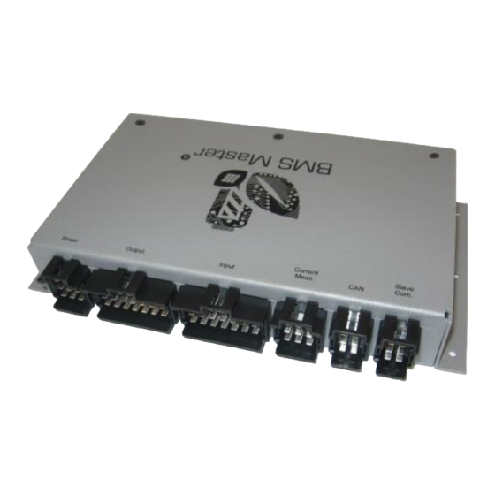
Hardware Manual BMS Master 4 / 4.5 3.1.5. MASTER C UMMARY ONNECTORS TYCO Connector Pinning Summary Supply Outputs Inputs Current CAN Slave Comm. CN101 POWER KL30 KL15 KL31 KL30 KL15S KL31 KL30 EMSRET KL31 CN102 OUTPUTS REL1A REL1B REL2A REL2B... -
Page 23: Electrical Specification
Hardware Manual BMS Master 4 / 4.5 3.1.6. LECTRICAL PECIFICATION Supply Condition Unit Sleep Mode, Master OFF, KL 30 28.0 suppsl Standby/Operating, Master ON, KL 28.0 suppop 30, KL 15 ON Voltage Real Time Clock Data suppdr Retention RTC data retention time with no... -
Page 24: Environmental Conditions
Hardware Manual BMS Master 4 / 4.5 Provide a space of min. 180 x 230 x 40 mm for the device with all connectors plugged. 3.1.8. NVIRONMENTAL ONDITIONS Operating temperature: -20°C ... +70°C Storage temperature: -20°C ... +80°C Humidity: max. 95% not condensing EMC: EN 61000-6-1:2007;... -
Page 25: Connection To The Master
Hardware Manual BMS Master 4 / 4.5 48.00 PTSA25-6 do not connect Sense 1 Sense 2 Compensation 1 Compensation 2 54.00 3.2.1.1 MASTER ONNECTION TO THE The picture shows the wiring between the Current sensor VAC4645 VAC_PCB board and connector CN104 on BMS_MASTER. -
Page 26: Current Divider 5:1
Hardware Manual BMS Master 4 / 4.5 3.2.1.2 URRENT IVIDER The current divider is to be used together with the 100A current sensor from Vacuum- schmelze in applications with currents up to 500 A. The sensor’s low current range cannot be used with the divider. -
Page 27: Bat-S 1000 1U Sensor
Hardware Manual BMS Master 4 / 4.5 If the current divider is wrongly calibrated, the switch-off current may not be reached. In this case there will be no safety switch-off! Due to the electromechanical uncertainties the current divider should only be used in prototypes and testing. -
Page 28: Measurement Values
Hardware Manual BMS Master 4 / 4.5 3.2.2.2 EASUREMENT VALUES current direction Current Measurement: Is A connected to positive and B connected to negative the measurement values is positive. Is A connected to negative and B connected to positive the measurement value is negative. -
Page 29: Connecting The Bat-S 1000 1U Sensor For Voltage Measurement
Hardware Manual BMS Master 4 / 4.5 of twisted pair cables is required. The shield is connected to the BMS Master only. 3.2.2.4 BAT-S 1000 1U ONNECTING THE SENSOR FOR VOLTAGE MEASUREMENT For voltage measurement the 2-pole MicroFit-connector is used. The two pins are shorted internally. -
Page 30: Ivt-B Sensor
Hardware Manual BMS Master 4 / 4.5 3.2.3. IVT-B S ENSOR The current sensor IVT-B by Isabellenhütte is a shunt sensor with isolated CAN interface. Air- and creepage distances are sufficient for 500 VDC. Additionally the sensor has a quasi-synchronous voltage measurement interface and an internal temperature measurement. -
Page 31: Connecting The Sensor For Voltage Measurement
Hardware Manual BMS Master 4 / 4.5 termination, necessary only with long cables as the MASTER-CAN2-interface has termination inside. For CAN-H and CAN-L usage of twisted pair cables is required. The shield is connected to the BMS Master only. 3.2.3.3... -
Page 32: Insulation Monitoring Ir155-3204
Hardware Manual BMS Master 4 / 4.5 IR155-3204 NSULATION ONITORING The BMS MASTER is prepared for the cooperation with the Bender insulation monitor IR155-3204. Only one insulation monitoring device may be used in each interconnected system. When insulation or voltage test are to be carried out, the device shall be isolated from the system for the test period. -
Page 33: The Hardware Of Slave_C
Hardware Manual BMS Master 4 / 4.5 SLAVE_C ARDWARE OF This chapter describes the following aspects of the BMS SLAVE_C hardware: external inputs and outputs internal structure environmental requirements 3.4.1. UNCTIONAL VERVIEW The slave module covers the following functions: ... -
Page 34: Block Diagram
Hardware Manual BMS Master 4 / 4.5 3.4.2. LOCK IAGRAM Power Single Cell Interface Supply 2nd Level Over Additional Voltage and voltage Balancing Balancing Temperature and temperature Resistors Resistor Measuring Detection Interface Isolated Serial RS 485- Communic. Interface to BCS Master Config. -
Page 35: Functional Description
Hardware Manual BMS Master 4 / 4.5 3.4.4. UNCTIONAL ESCRIPTION 3.4.4.1 OWER UPPLY The CPU and peripherals are supplied by linear regulated 5VDC derived from the mid cell voltages number 6 to 8, min. 5.4V to 12.6V, connected to cell contacts 7 … 10. -
Page 36: Connecting Less Than 10 Cells
Hardware Manual BMS Master 4 / 4.5 3.4.4.3 ONNECTING LESS THAN CELLS Cell-Contact ONLY with NOT modified hardware. The connections between the single contacts as depicted must be realized on the edge connector 10 Cells Z10- n.c. 9 Cells n.c. -
Page 37: Balancing Resistors
Hardware Manual BMS Master 4 / 4.5 3.4.4.4 ALANCING ESISTORS To achieve properly balanced cells a resistor of 68Ω/0.5W can be switched parallel to each single cell to reduce the charging current with appr. 60 mA. The status of each of these switches is visualised with 10 LEDs. -
Page 38: Configuration Interface
Hardware Manual BMS Master 4 / 4.5 Pin numbers counting from left to right with the PCB battery interface on top. See chapter 3.4.3 page 34 Due to double pin assignment every signal may be connected twice to achieve proper connections with one wire per cage only. -
Page 39: Signalling Leds
Hardware Manual BMS Master 4 / 4.5 Temp Sensor 1 (NTC) Connector Assignments, Temp Sensor 1 (NTC) Pin numbers counting from Temp Sensor 2 (NTC) top to bottom with the Temp Sensor 2 (NTC) Overtemp PTC PCB battery interface on top. -
Page 40: Long Time Watchdog
Hardware Manual BMS Master 4 / 4.5 3.4.4.11 ATCHDOG On the Slave PCB a slow RC-generator (approximately 3 Hz) clocks a multistage divider IC that has to be reset periodically by the MASTER. If no reset happens, e.g. caused by an unsupplied MASTER, the divider IC cuts off all balancing circuitry to prevent totally discharging of the battery. -
Page 41: Environmental
Hardware Manual BMS Master 4 / 4.5 3.4.7. NVIRONMENTAL Operating temperature: -20°C ... +70°C (t.b.d) Storage temperature: -40°C … +85°C Humidity: max 95% not condensing. At pollution level 1 the Slave C may be operated up to 1000V At pollution level 2 the Slave C may be operated up to 650V... -
Page 42: The Hardware Of Slave_5
Hardware Manual BMS Master 4 / 4.5 SLAVE_5 ARDWARE OF The BMS SLAVE_5 is part of the modular Battery Monitoring System by ACTIA I+ME. With one SLAVE_5-Modul from 5 … 10 single lithium cells may be controlled; up to 31 SLAVE_5- Modules may be connected to one MASTER unit;... -
Page 43: Functional Overview
Hardware Manual BMS Master 4 / 4.5 3.5.1. UNCTIONAL VERVIEW The SLAVE_5 modules cover following functions: Communication with master module Measurement of single cell voltages Balancing of different cell charges Control of the mechanical integrity of one or several cells ... -
Page 44: Board Layout And Connections
Hardware Manual BMS Master 4 / 4.5 3.5.3. OARD AYOUT AND ONNECTIONS Cell voltages and temp sensors Config-Interface normal operation pin use configuration pin use cell 1+/2- cell 1- n.c. n.c. cell 3+/4- cell 2+/3- n.c. n.c. cell 5+/6- cell 4+/5- n.c. -
Page 45: Functional Description
Hardware Manual BMS Master 4 / 4.5 3.5.4. UNCTIONAL ESCRIPTION 3.5.4.1 UPPLY CPU and peripherals are supplied with a linear regulator with 5V out of cells 6, 7 und 8, (connector pins 3, 16, 4, 17) from 5.4 to 12.6 V The internal reference point for all voltages is always connector pin 3;... -
Page 46: Sensor- And Ptc-Interface
Hardware Manual BMS Master 4 / 4.5 3.5.4.4 PTC-I ENSOR NTERFACE According to the slave software an NTC-resistor with a cold resistance of 10 k at 25 °C has to be used as temperature sensor. To supervise the cells on over temperature a PTC-resistor may be mounted on each cell surface. -
Page 47: Serial Rs 485 Interface And Error Signalling
Hardware Manual BMS Master 4 / 4.5 The resistor values are adapted on the voltage range of the cell voltages. Thus an optimum between maximum balance current and maximum board temperature is reached. All resistor connection points rsp. all cell connection point are led to a 22-pole MicroFit- connector, to give the possibility for balancing currents of up to 500 mA using an external balancing resistor board or even only one resistor near every cell. -
Page 48: 2Nd-Level Overvoltage Detection
Hardware Manual BMS Master 4 / 4.5 to MASTER 3.5.4.7 EVEL VERVOLTAGE ETECTION Every single cell voltage is supervised by a “second level security chip”, activating the FAIL-output if only one cell voltage exceeds 4.4 V for more than one second (other threshold voltages are possible, but the realization depends on quantity. - Page 49 Hardware Manual BMS Master 4 / 4.5 8.2 Ω and 4 V cell voltages. When connecting external balancing resistors in applications with less than 10 cells it has to be considered to adapt the schematics below relatively to line Z5+/Z6-. Those cells replaced by a short connection (see 3.5.4.3) have to be removed from the schematics...
- Page 50 Hardware Manual BMS Master 4 / 4.5 22pol Stecker 24pol Stecker 22pol Conn. 24pol Conn. Z10+ Cell 10 Z9+/10- Cell 9 Z8+/9- Cell 8 Z7+/8- Cell 7 Z6+/7- 24pol Cell 6 Z5+/6- SLAVE 5 Cell 5 Z4+/5- Cell 4 Z3+/4-...
-
Page 51: Interface Isolation
Hardware Manual BMS Master 4 / 4.5 The sense lines to the single cell voltages may be connected ONLY to the 24-pole connector; external balance resistors may be connected ONLY to 22-pole connector. The pins 1 … 10 of the 22-pole connector may be used only, when there is no other possibility to connect the balance resistors directly to the cell contacts. -
Page 52: Environmentals
Hardware Manual BMS Master 4 / 4.5 Peak consumption while communicating with MASTER ~ 20 mA Stand-by/sleep-mode with MASTER inactive ≤ 0.03 mA Balancing current per cell without external resistors (voltage dependent) 70 ... 90 mA 3.5.9. NVIRONMENTALS Humidity: max 95%, non-condensing Working temperature: -20°C ... -
Page 53: The Hardware Of Slave 6
Hardware Manual BMS Master 4 / 4.5 ARDWARE OF LAVE Slave 6 is a part of the modular Battery Management System of ACTIA I+ME. The Slave 6 hardware consists of 3 different modules. 1x SL6_CON module (control module) communication interface to the Master and to the SL6_ANA modules ... -
Page 54: System Block Diagram
Hardware Manual BMS Master 4 / 4.5 3.6.4. YSTEM LOCK DIAGRAM SL6_ANA-module Second Level Hardware dection 2 x Temperature Sec. Level Hardware Configuration Batt. 4...12 cells 10...60V Voltage Temperature Measureing Cell Balance 3 x Temperature SL6_ANA-module Second Level Hardware dection 2 x Temperature Sec. -
Page 55: Connecting The Slave 6 Con Module To Master
Hardware Manual BMS Master 4 / 4.5 3.6.5. C 6 CON M MASTER ONNECTING THE LAVE ODULE TO Molex MicroFit 12-pol (view of the connector at the device) CN104 Tyco 9-pol VNET 7V /12V KL31 Shield FAILB CANL... -
Page 56: Communication Connection To Con Module - Ana Module
Hardware Manual BMS Master 4 / 4.5 3.6.6. C CON M - ANA M OMMUNICATION ONNECTION TO ODULE ODULE SL6_ANA Top SI-B EN-B Shield SI+B EN+B Shield SL6_ANA Bottom Shield EN+T SI+T Shield EN-T SI-T Typical cable between: - SL6_C and SL6A module... -
Page 57: Sl6_Con Module
Hardware Manual BMS Master 4 / 4.5 The communication cables must be shielded twisted pair. The signal pairs B1/B2 and T1/T2 may not be exchanged; T1 connects to B1 and T2 connects to B2 of the next module. The return signals (signal SI+-B) are only present if the hardware error detection recognizes no error. -
Page 58: Mechanical Dimensions
Hardware Manual BMS Master 4 / 4.5 CON module, 12 pole connector to BMS Master Signal Description VNET Power Supply from Master, typical 12VDC (9…16) 2, 8 TERM L/H Activation CAN termination resistor 120 Ohm (short Pin 2- 8) 3, 4... -
Page 59: Supply And Current Consumption
Hardware Manual BMS Master 4 / 4.5 Attention: The mounting holes do NOT comply with the requirements of 10 mm air and creepage distances for high voltages. If the slave modules are used under these conditions non- conductive screws and/or bolts must be used. -
Page 60: Sl6_Ana Module
Hardware Manual BMS Master 4 / 4.5 3.6.8. SL6_ANA M ODULE 3.6.8.1 OARD AYOUT AND ONNECTORS 14-pole connector, cell voltage, view of the 10-pole connector, temperature sensor, view of the connector at the device connector at the device Sensor Sensor... - Page 61 Hardware Manual BMS Master 4 / 4.5 ANA module, 14 pole connector – cell voltage Signal Description Cell 1 Minus Cell 1 Plus, Cell 2 Minus Cell 2 Plus, Cell 3 Minus Cell 3 Plus, Cell 4 Minus Cell 4 Plus, Cell 5 Minus...
-
Page 62: Connect Less Than 12 Cells
Hardware Manual BMS Master 4 / 4.5 4, 8 SI+B, Differentially Return–Signal to CON module or to previous ANA- SI-B module (ca. 10kHz) ANA module, 8 pole connection Top – communication to the next module Signal Description 1, 5 T1, T2 Differentially ISO SPI signal to the next ANA –... - Page 63 Hardware Manual BMS Master 4 / 4.5 n.c. CV11 11 cells CV11 CV10 n.c. CV10 10 cells CV10 CV10 n.c. 9 cells n.c. 8 cells n.c. 7 cells n.c. 6 cells Ref.: IR14417 A 15.01.2018 Page 63/76...
-
Page 64: Second Level Protection
Hardware Manual BMS Master 4 / 4.5 n.c. 5 cells n.c. 4 cells 3.6.8.3 ECOND EVEL ROTECTION The SL6 ANA module contains a hardware circuit to check the cell voltage of every cell and cell temperature (sensor 4, 5). Are the values over the limits, the FAIL signal of the SL6 CON module becomes active. -
Page 65: Supply And Current Consumption
Hardware Manual BMS Master 4 / 4.5 3.6.8.6 UPPLY AND URRENT ONSUMPTION The SL6 ANA is powered from the connected cells. Description Value Unit Max. Supply voltage (from the cells) 12…55 Connection CV0 - CV12 Max. voltage between connections (CV0 – CV1) -0.3 …... -
Page 66: Connection Of External Balance Resistors
Hardware Manual BMS Master 4 / 4.5 Modul Balance current cell type Slave 6 A 2X 20,5 Ohm U [mV]: 1500 … 2800 I [mA]: 73 … 137 Cell type: LTO cell Slave 6 A 3X 27,5 Ohm U [mV]: 2500 … 3600 I [mA]: 91 …... - Page 67 Hardware Manual BMS Master 4 / 4.5 600mA. The resistor load must be enough. For sufficient cooling is to ensure! The cell voltage measurements wires are only connect to 14 pole connector. To connect the external Balance Resistors use only the 24 pole Connector.
- Page 68 Hardware Manual BMS Master 4 / 4.5 14pol 24pol connector connector Sense Lines Balance Lines CV12 Cell 12 CV11 Cell 11 CV10 Cell 10 Cell 9 Cell 8 Cell 7 14pol Cell 6 SL6_ANA Cell 5 Cell 4 Cell 3...
-
Page 69: Bringing The Slave C, Slave 5 Into Service (Only For Cell Voltages)
Hardware Manual BMS Master 4 / 4.5 C, S RINGING THE LAVE LAVE INTO ERVICE ONLY FOR OLTAGES A startup example of Slave5 and Slave C is represented. VBAT- 24-pol Conn. VBAT+ 8-cell-wiring 12 11 10 9 8 7 6 5 4 3 2 1... - Page 70 Hardware Manual BMS Master 4 / 4.5 VBAT- VBAT+ 8-cell-wiring 12 11 10 9 8 7 6 5 4 3 2 1 Power Slave Com. Vbat Power Supply Drive e.g. LiYCY- TP 3x2 0,25mm² Accordingly one Slave after the other has to be connected to the RS485 bus and be taken in function.
-
Page 71: Connectors-Accessory
Hardware Manual BMS Master 4 / 4.5 ONNECTORS CCESSORY Order Numbers 24-pole connector: MPE-Garry 433-2-024-X-KSO Molex 43025-2400 Nexus 2300P-24 Würth 662024113322 Order Numbers 22pole connector: MPE-Garry 433-2-022-X-KSO Molex 43025-2200 Nexus 2300P-22 Würth 6620226113322 Order Numbers 14-pole connector: MPE-Garry 433-2-014-X-KSO Molex... - Page 72 Hardware Manual BMS Master 4 / 4.5 Nexus 2300T-B/-F/-T Würth 66210113722 Order Numbers Crimp-Tool: MPE-Garry 454-1-05 The articles by Molex, Nexus and Würth are not guaranteed to be fully compatible; use is on own risk. Ref.: IR14417 A 15.01.2018 Page 72/76...
-
Page 73: Certificates
Hardware Manual BMS Master 4 / 4.5 ERTIFICATES Ref.: IR14417 A 15.01.2018 Page 73/76... - Page 74 Hardware Manual BMS Master 4 / 4.5 Ref.: IR14417 A 15.01.2018 Page 74/76...
- Page 75 Hardware Manual BMS Master 4 / 4.5 Ref.: IR14417 A 15.01.2018 Page 75/76...
- Page 76 Hardware Manual BMS Master 4 / 4.5 Ref.: IR14417 A 15.01.2018 Page 76/76...
Need help?
Do you have a question about the BMS Master 4 and is the answer not in the manual?
Questions and answers